Week 8 - Challenge 2 - Switch Bezel Design
AIM:The objective of the project is to design the switch bezel and to do a draft analysis for it by creating the required tooling direction with the help of TOOLING AXIS METHOD and perform draft analysis.
INTRODUCTION:
Switch Bezels in car are parts which contains switches and controls for different functions like Window control, Door lock/Unlock,Media and Temperature controls. Moulding is the method used to manufacture the plastic trims of an automotive.
REPORT-
CONSIDERATION :
- Class – A surface should be aesthetically smooth
- Class – B surface should have all the supporting features like ribs.
- Parting Line should coincide with the B surface since flashing couldn’t affect the aesthetic of Class – A.
- Class – C surface should also pass the draft analysis.
Objective:
- Geometrical sets should have a proper name based on the sketches present inside them.
- All the sketches should be created under the Geometrical set.
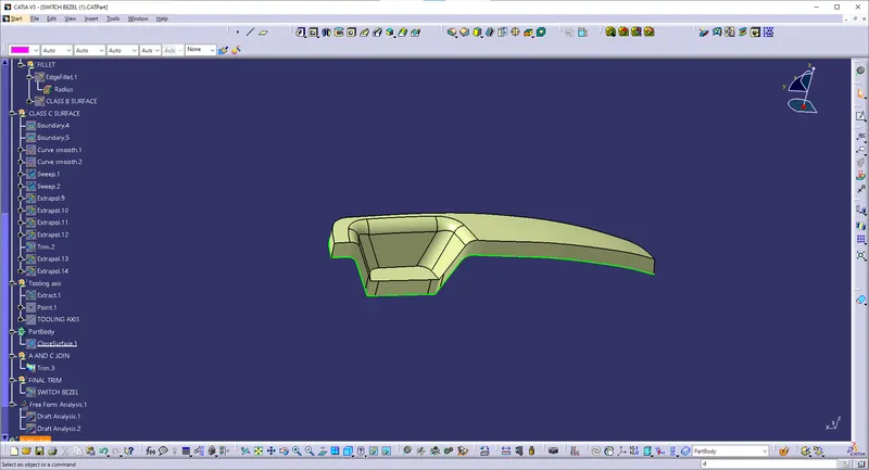
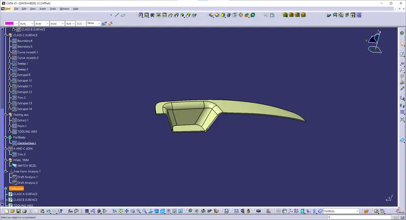
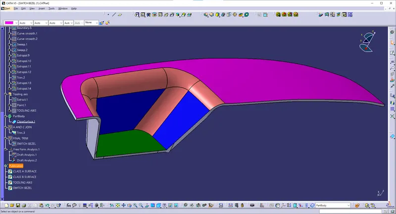
- Use the CLOSE SURFACE feature to make a solid body from the surface.
- To publish the Tooling Axis, Class A, B, and C surface.
- Ensure Proper Tree Structure.
DRAFTING ANALSYIS FOR CLASS A SURFACE :
- the mold after manufacturing the interior trim must have the 3-degree draft angle.
- Hence the tooling direction is created by considering the above factor and TOOLING METHOD is used.
- CLASS A BASE is extracted and a point at the centre is created with referance to the base of CLASS A.
- Then, using project intersection along yz plane is created and the two inclined lines were drawn inside the positioned sketch.
- DRAG THE COMPASS TO THE AXIS LINE AND CLICK DIRECTION .
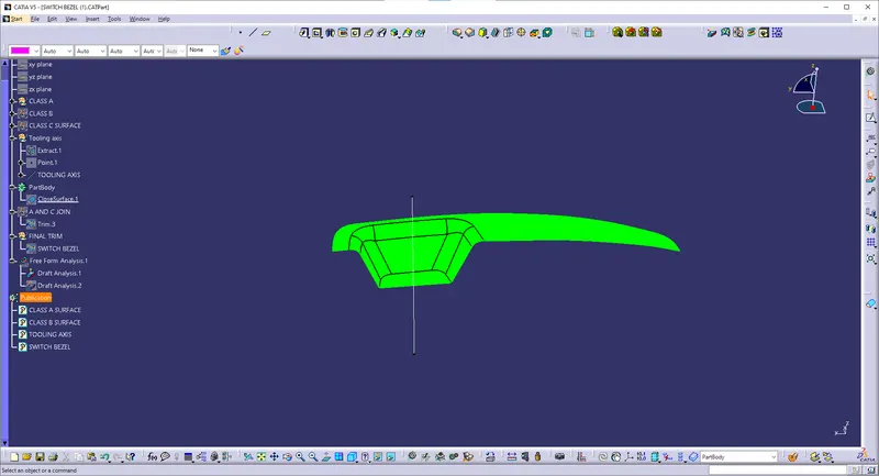
CLASS A SURFACE:
- Go to insert- analysis- feature draft analysis
- Align the tooling axis with the compass.
- Click on the surface and see that the surface is within the permissible limit of the draft values.
- The surface should be green and in the column nominal value 3deg given as input. hence the draft analysis on the class-A surface is successfully performed.
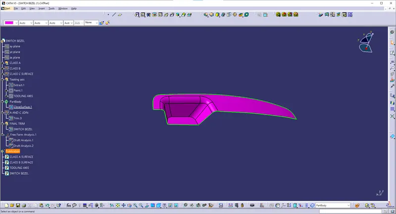
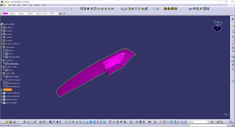
CLASS B SURFACE:
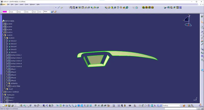
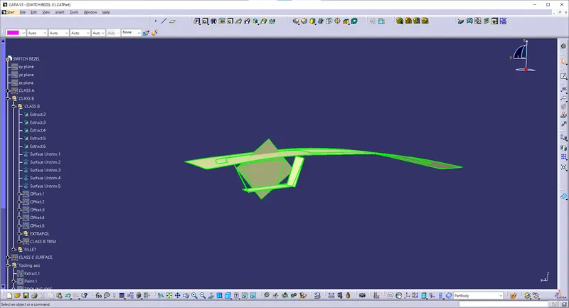
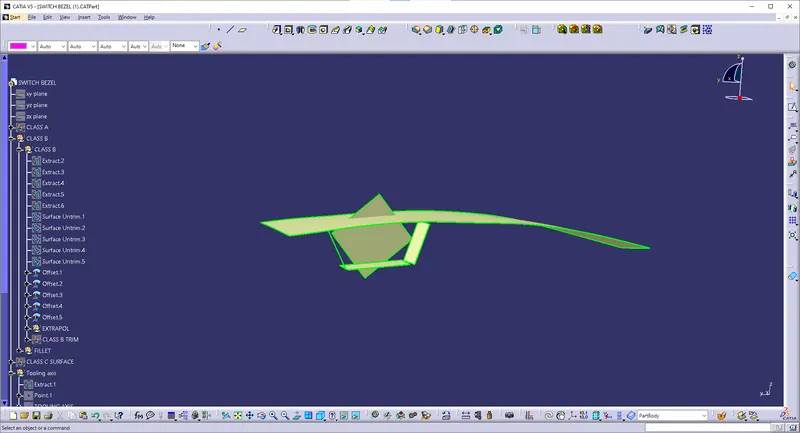
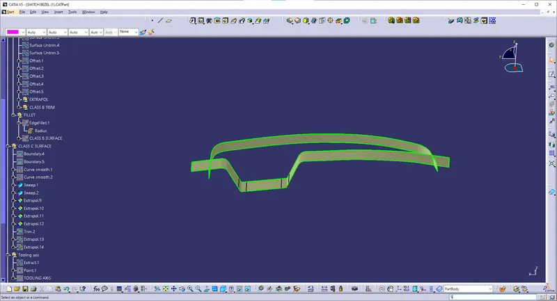
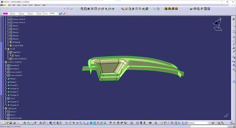
- For creating the class-B surface the required surface except the offset surface have been extracted and then untrimmed all the surface.
- Then all the surfaces have been extrapolated to get intersections between them.
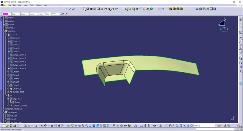
- Since the thickness of the Switch bezel is 2.5mm the B-Surface was offset to 2.5 mm and the required trim operations must be carried out.
- THEN fillet of 11.5 and 17.5 are given.
Class C SURFACE:
- It is the combination of Class A, Class B and Class C surfaces.
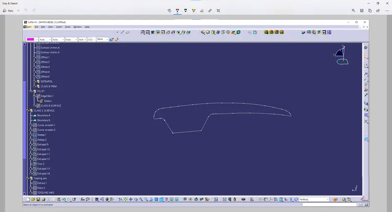
- To create a class C surface, I used the sweep command by considering the outer boundary of the class A surface.
- In the sweep command, go to the 'line' command in the 'profile' block and the subtype is 'with draft direction'.
- Now select the outer boundary and tooling axis, give 3 deg in the angle (the draft angle for a plastic component is 0.5 to 3 deg) and select the direction to sweep, in this condition the class B surface is under the class A surface so select the inside down arrow to sweep.
- The same procedure is repeated for the two circles on the class A surface. Now I joined all the sweeped surfaces by using the 'join' command and then I trimmed the Class A, Class B and Class C surfaces to make a closed surface, to make a Solid body.
OPERATION'S:
- BOUNDARY
- SWEEP
- SMOOTH CURVE'S
- EXTRAPOL
- TRIM
- MULTIPLE EXTRACT
- JOIN
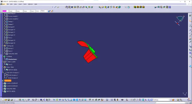
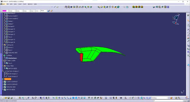
DRAFT ANALYSIS OF CLASS C:
For this analysis, main tooling axis is taken draft reference.
Following results were obtained:
SOLID BODY:
CONCLUSION:
The Design of Plastic Component - Base Bracket from Class A is completed using concepts of Draft angle, Draft Analysis, Tooling Axis, Class B and Class C creation and converting Closed surface to a solid part.