Week 8 - Challenge 1 - Base Bracket Design
Aim:
To create the Base Bracket Plastic Component through the given Class-A Surface and to perform Draft Analysis on the final plastic component using CATIA V5 tool.
Objectives:
- Creation of Tooling Axis with bisecting method.
- Creation of Class B and Class C surfaces.
- Creating a solid part from the surface using close surface feature.
- Perform draft Analysis of final plastic component.
Introduction:
This project aims to create a base bracket using a given Class A surface. The approach includes creation of Class B and Class C surfaces keeping 2.5 mm thickness in mind for the complete component.
Design Constraints:
- ALTERATION OF CLASS A IS NOT ALLOWED.
- ALL SURFACES SHOULD BE CLOSED BEFORE CONVERTING TO SOLID.
ALL FACES SHOULD MEET THE ALLOWED DRAFT REQUIREMENTS.
Procedure:
- Class A surface
- Class A surface is used as the parent reference to begin the design of a product.
- To continue with the design process, we need to find out the tooling axis for surface-A.
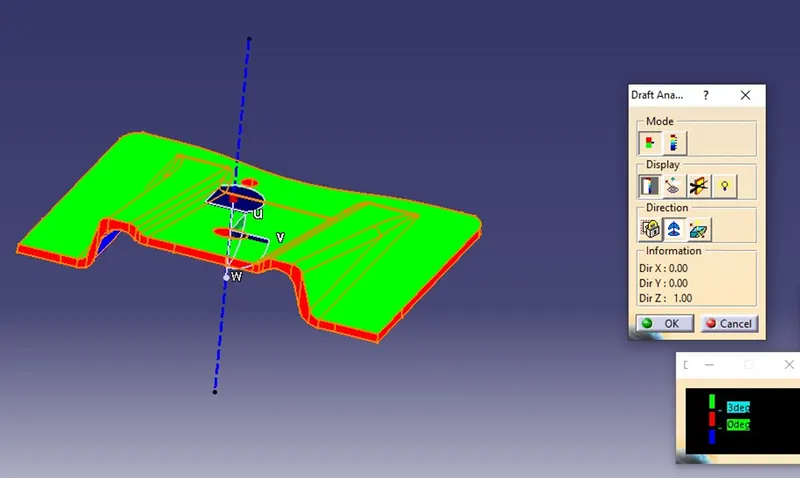
- Next step is to check for all the drafts using Draft Analysis tool of CATIA V5.
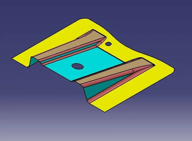
- Draft Analysis for Surface A
- The Drafting analysis is performed using the Feature Draft Analysis command from INSERT menu
- The drafting analysis is done with 3 degree draft angle.
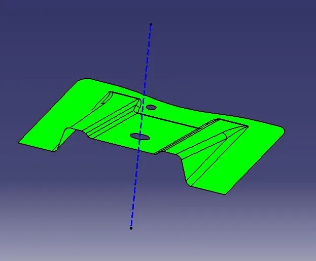
- Creation of Tooling Axis
- A dummy Tooling axis is created using a reference point created on a hole of the given surface.
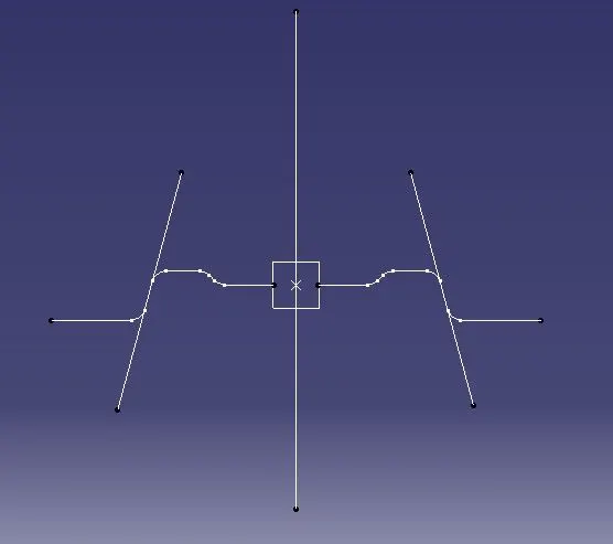
- Create an intersection of CLASS A surface with YZ plane.
- Tooling axis is created from these two lines as shown in above image using Bisecting option.
- The central line shown in figure is the tooling axis.
- Creation of Class B surface
- Class B surface is created from the Class A surface.
- Extract the surface from Class A using Extract command and untrimmed followed by Extrapolate if required, to obtain the original parent surface.
- The same procedure is followed on the other side as well.
- The resultant surfaces are then trimmed to form the Class B surface which is offset at a required thickness from Class A surface.
- Finally all the necessary fillets were added to the Class B surface.
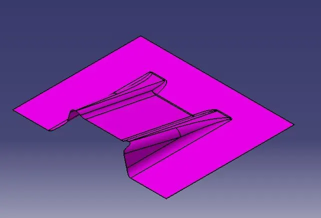
- Creation of Class C surface
- Class C surface connects the Class A and Class B surface.
- For creating Class C surface, initially the boundary of Class A is extracted using Boundary
- Then Sweep command is used along the draft direction, with a 3 degree draft angle.
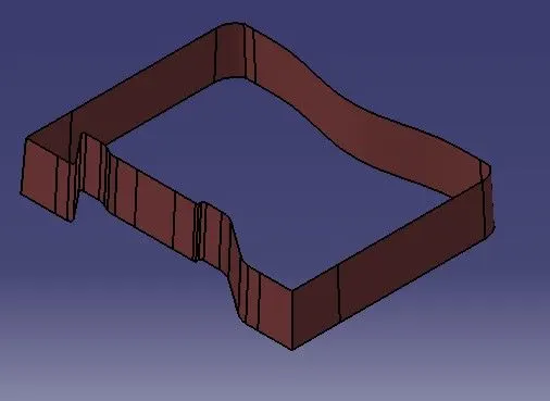
- Join Class A and Class C
- The holes present in the surface are created using boundary command and Sweep command.
- To make Class A and Class C as a single body, both surfaces are joined using Join This command is used to make sure that there is no any open boundary between Class A and Class C.
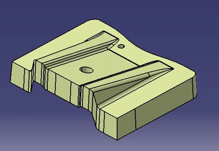
- Final trims:- Class A + Class B + Class C
- To obtain the final output, (shown in below figure) the joined Class A+C is trimmed with the Class B surface using trim feature.
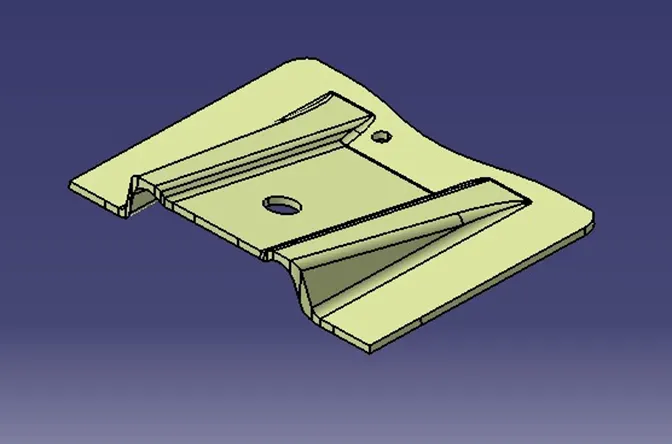
- Solid body is obtained using closed surface feature from part workbench.
- The Tooling axis, Class A, B and C surfaces were published.
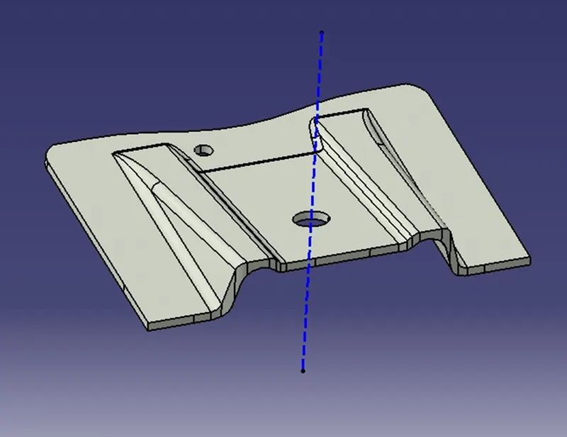
- Draft Analysis of the Final Component
- Main tooling axis is taken as the draft reference for this analysis.
Conclusion
Final output ‘”BASE BRACKET” is successfully published using CATIA VS tool.