Week 8 - Challenge 1 - Base Bracket Design
Base Bracket Design
creates Base Bracket Design for closed surfaces and also creates tooling axis and draft analysis.
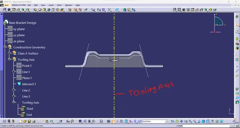
Tooling axis:
The direction between mold or core and cavity to easily eject the finished component during the molding.
Step:1
Check surface is closed surface to use the tools are boundary and the joint command used to check Class A surface.
Step:2
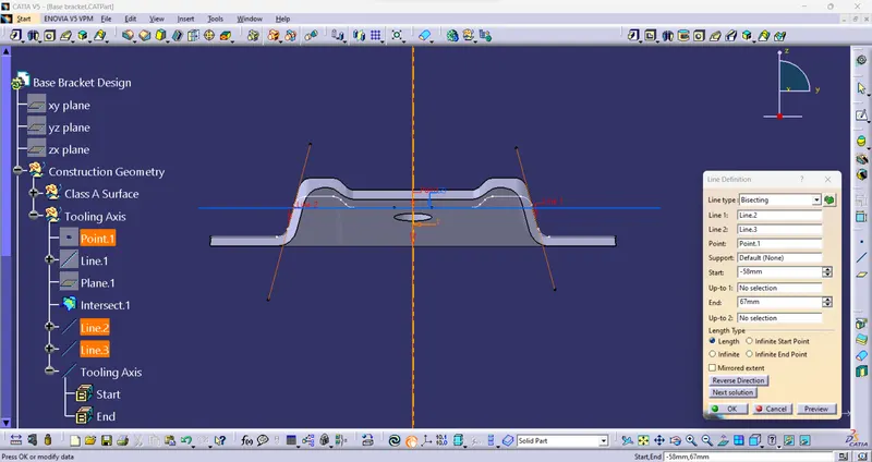
Create a point and line to one reference axis line for tooling direction. and also create the bisecting line.
Step:3
Bisecting line:
the bisecting line has created a line between two equal distances in this command creating on symmetry line for two equal distances.
- Generate two lines using point-to-point distance.
- Then create bisecting line use to two lines and one point to create line.
Class A Surface:
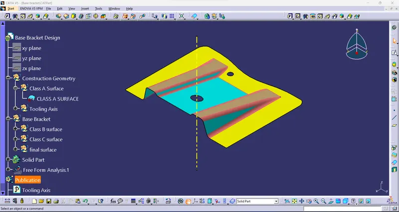
- Class ‘A’ surfaces are primarily used in the automotive environment and refer to those surfaces which are visible in a product.
- To get a Class A surface from a stylish team. and check and confirm its a fully closed surface or not.
Create class B surface:
- Class B is a second surface used to create the closed surface of class A and class B.
- Class B surface to be generated using the CATIA generative surface modeling.
- first, extract the required surfaces to trim the surface to generate the model.
- Then create a boundary for the class A surface to generate a drafting line sweep for 3° in the tooling axis.
- chamfer all the edges in 3+2.5 mm (radius 3+2.5mm thickness).
- Finally trim both surfaces to get one complete surface to switch part design to generate solid parts using the closed surface command.
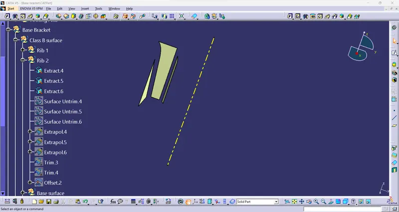
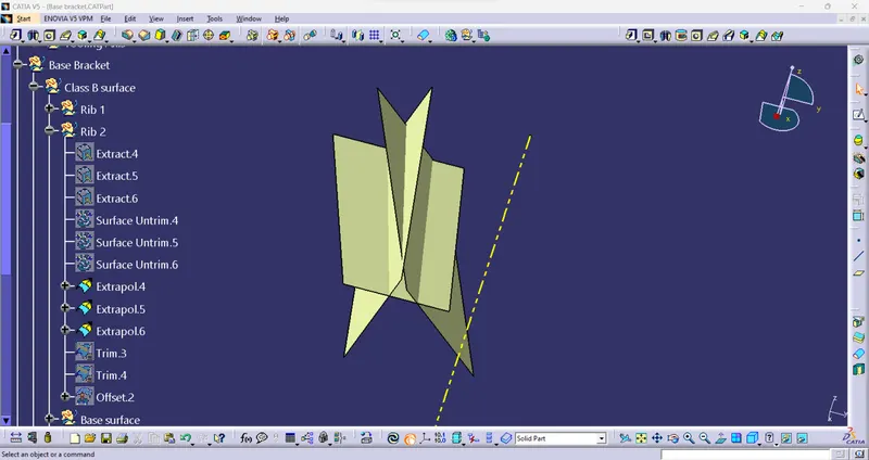
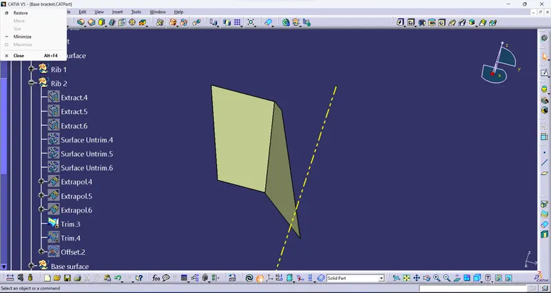
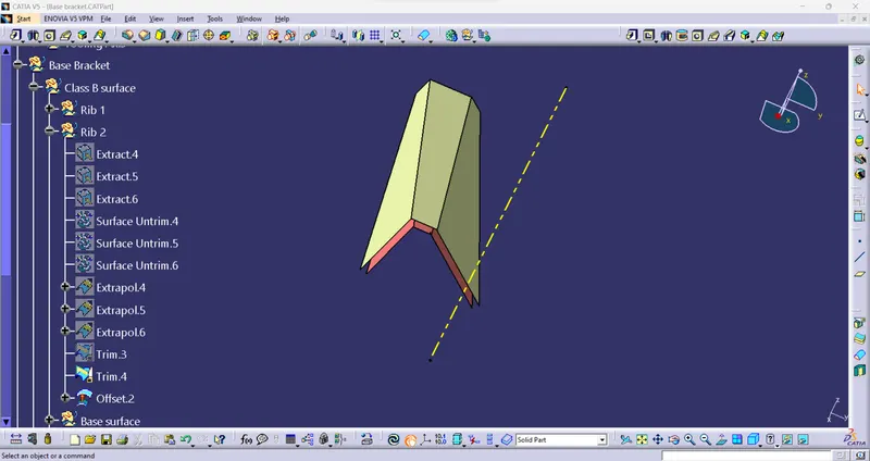
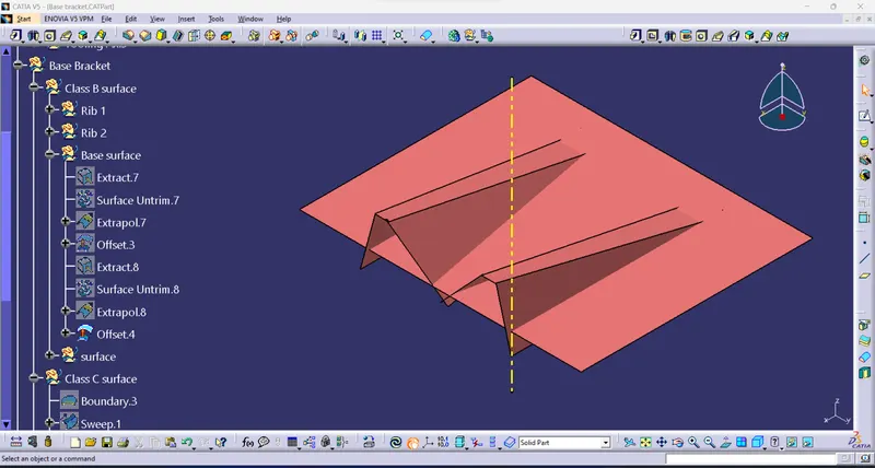
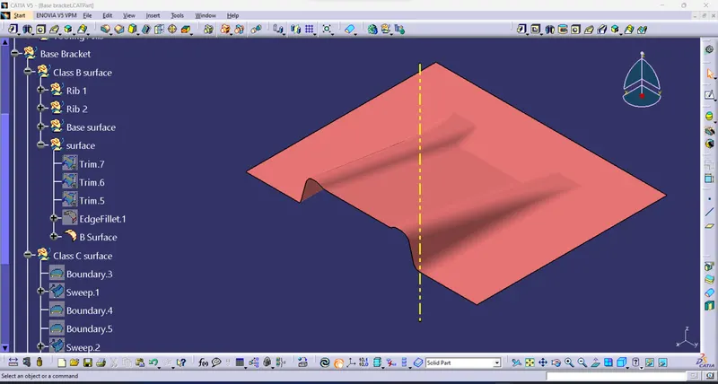
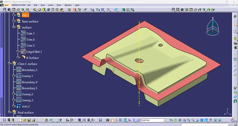
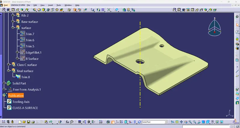
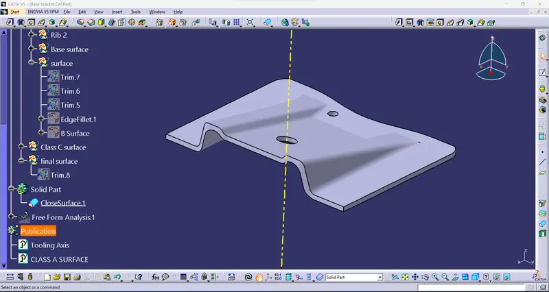
Class A surface:
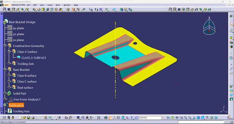
Class B surface:
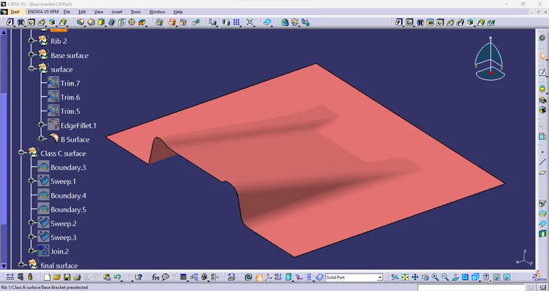
Class C surface:
Closed surface:
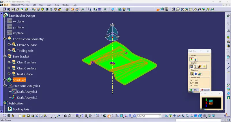
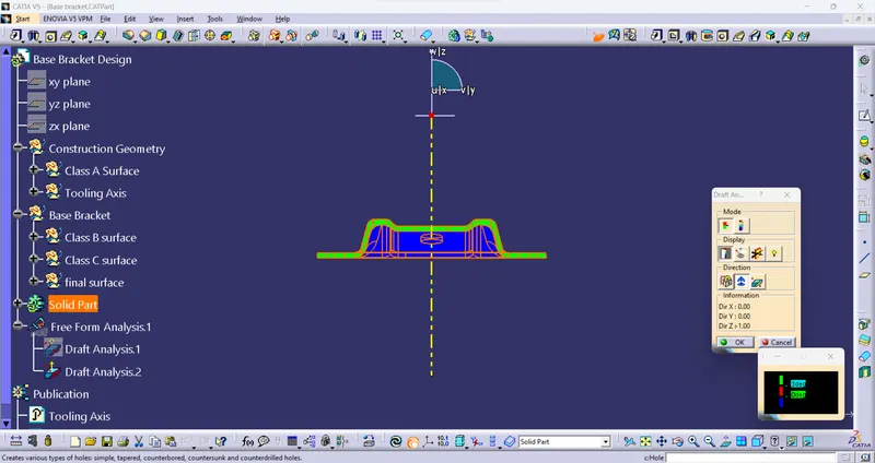
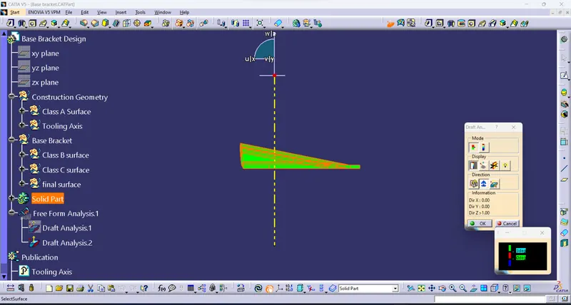
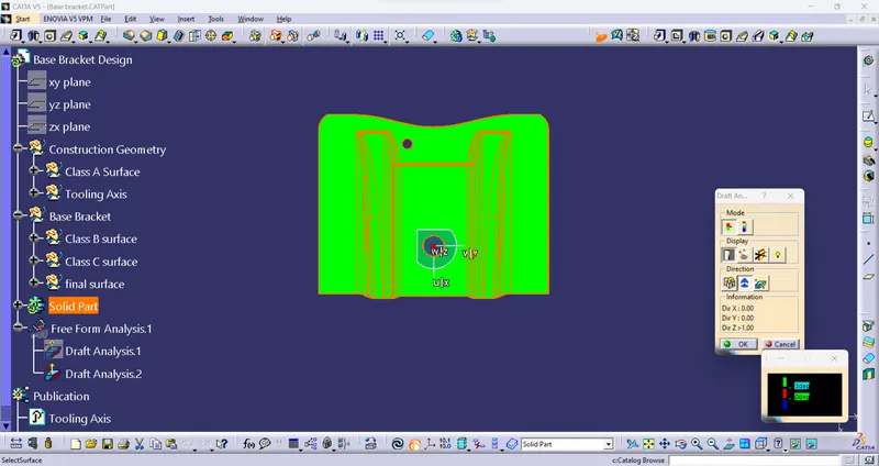
Drafting analysis:
- To analyze to part using tooling direction to eject the part during production.
- To analyze all the sides and all the angles of the parts to properly angled in the tooling direction.
- To check the tapered side in a 3° angle drafting angle.
- The Green color mentions the no defect the tooling axis is correct. but the color is mentioned under dimension and the red color is a defect or not the correct angle side.
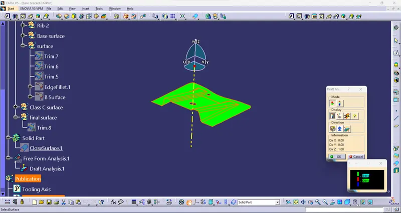
view:
Isometry view:
Front View:
Side View:
Top View:
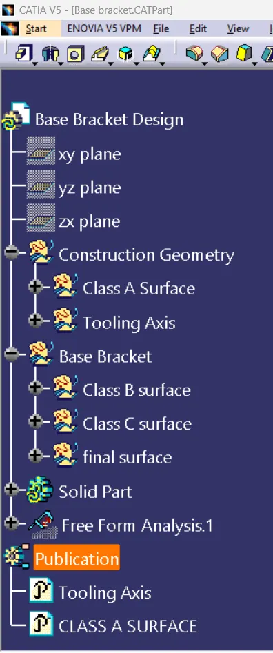
Tree:
- maintain proper geometrical set and the tree structure.
- create different geometrical sets for different usage
- show clearly mentioned geometrical set and part, the template in a tree structure.