Week 8 - Challenge 2 - Switch Bezel Design
Switch Bezel:
Create Switch Bezel for the given Class A surface to generate Class B and C surfaces to finally create the solid closed surface.
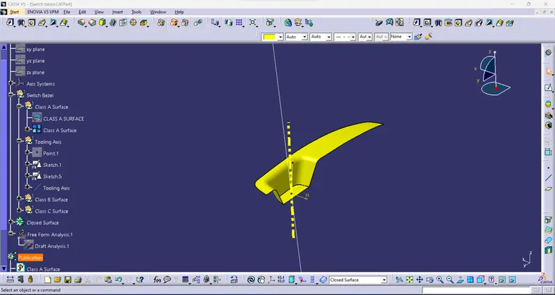
Tooling Axis:
The direction in which the mold or core and cavity open is the tooling axis.
creating tooling axis:
Sketch:1.
- Create a point for using extraction of the surface.
- Then create an axis coordinating system.
- Then create an intersection of the surface.
- create a line for the given intersection.
- finally generate Bisecting line.
Sketch:2.
- Then create an intersection in Y using an axis coordinating system.
- create a line for the given intersection.
- create a line for using a point to use dimension in 3° of the angle.
Bisecting line:
- Bisecting line equally distanced between two lines.
- sketch 1 & 2, point used to generate a bisecting line.
- this line is the tooling axis.
Switch Bezel:
Class A Surface:
- class a is an input to get the stylish team it was called Class A surface.
- check the class A surface to fully closed surface or not.
- the use to create class B surface.
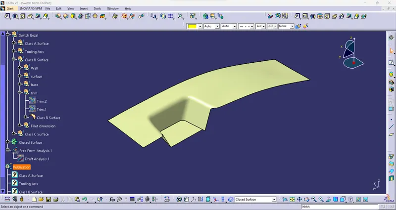
Class B Surface:
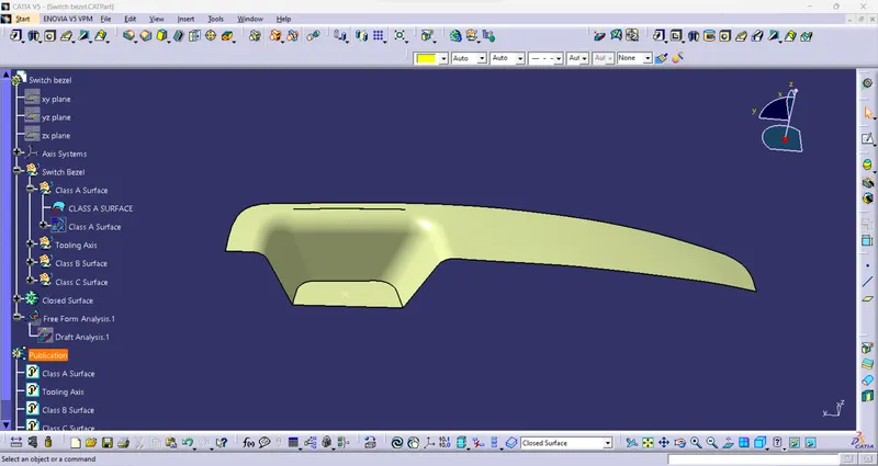
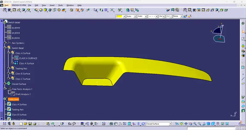
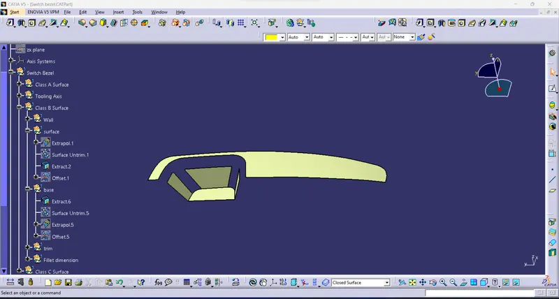
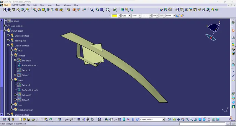
- Class B surface has extracted the surface from the class A surface.
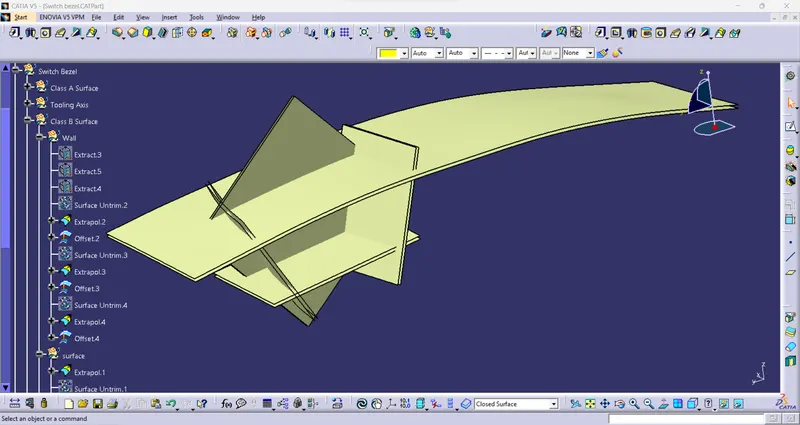
- Use the Extract the surface and untrim the surface.
- Then Extrapolate the untrimmed surface.
- then offset the surface for a given thickness 3mm distance.
- All the surface for the Wall, surface, and base.
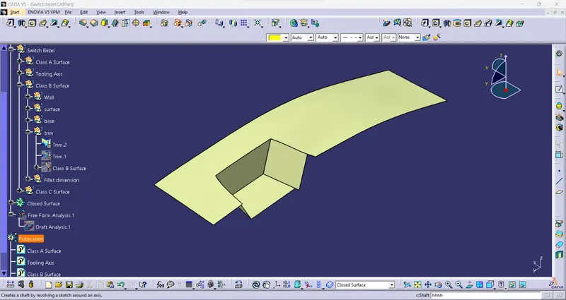
- Then trim the surface.
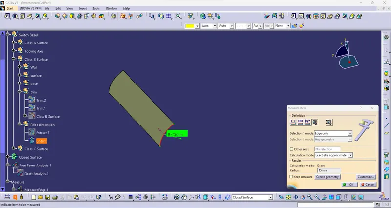
- Next fillet the surface.
- Finally, generate the Class B surface.
Class C Surface:
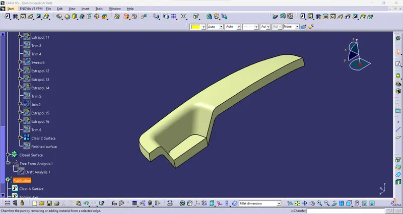
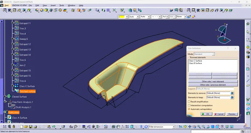
- Class B surface is a closed surface to generate the boundary of the Class A surface.
- Then trim both Class A and B surfaces to generate the Class C surface.
Closed surface:
- Create a closed surface for the given Class C surface.
- using Closed surface commend In part workbench.
- finally, generate the solid model.
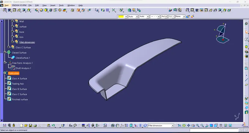
View:
Isometric View:
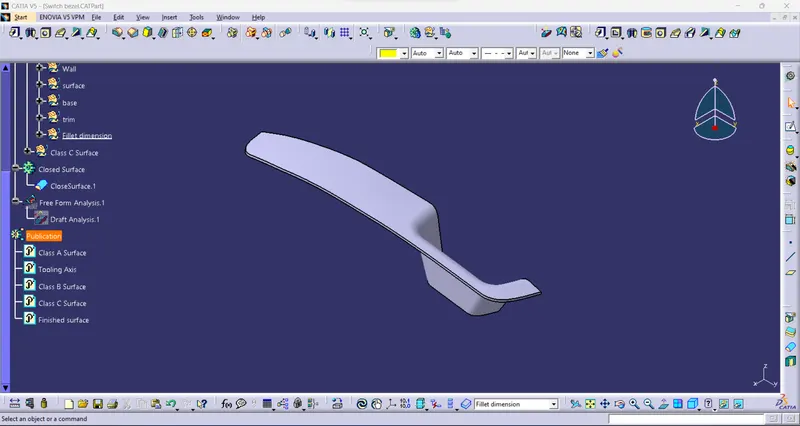
Front View:
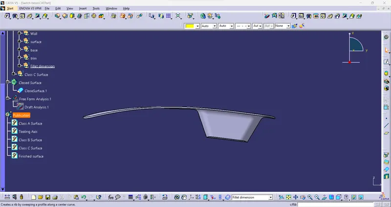
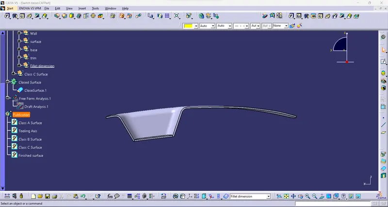
Side View:
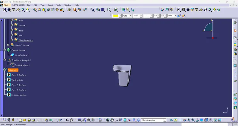
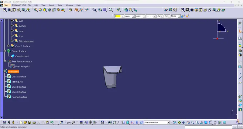
Top View:
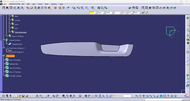
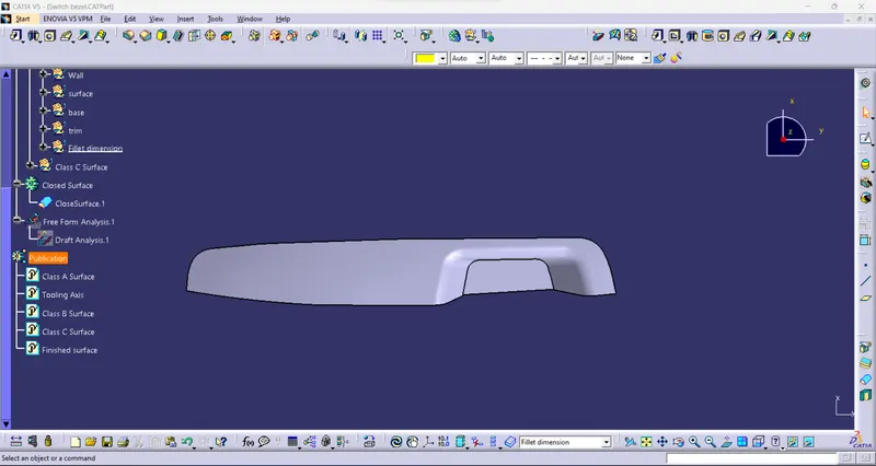
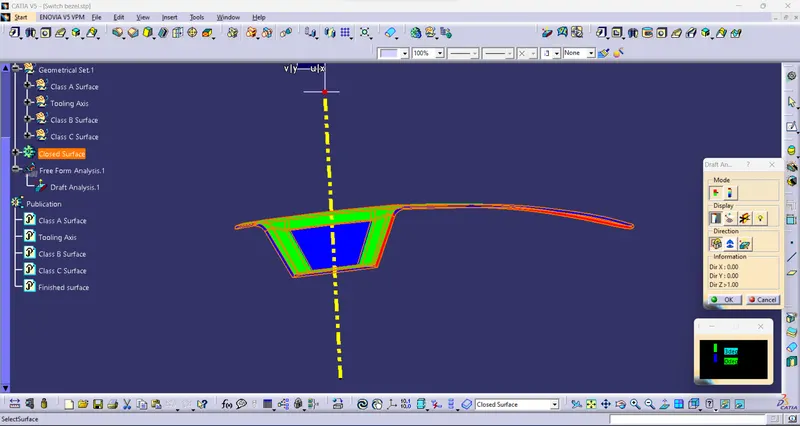
Draft Analysis:
- Analysis of the draft angle of the completed solid model.
- Using this command to check the possibility of the draft angle for tooling direction.
- The green color in the correct body or possible side.
- Blue is between the 0 to 3° angle.
- Red is a negative angle not possible.
- This draft analysis uses the tooling direction to analyze all the angles of the solid surface.
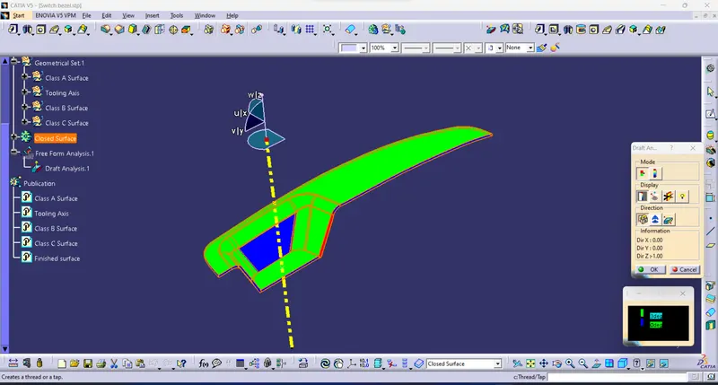
View:
Isometric View:
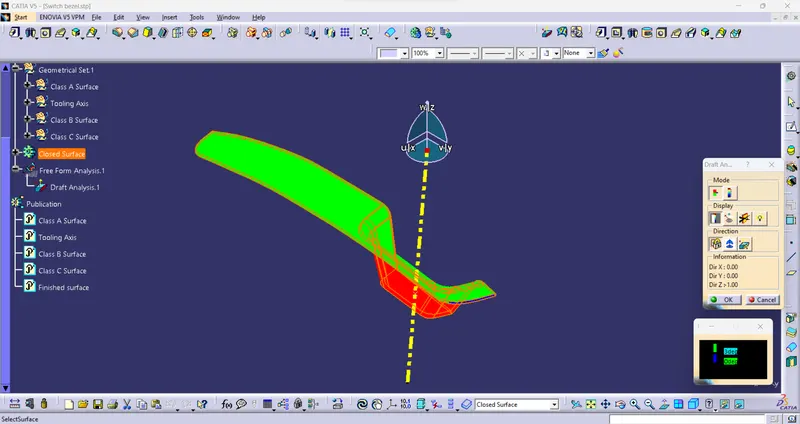
Front View:
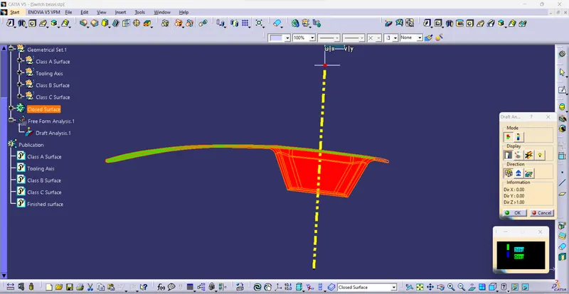
Side View:
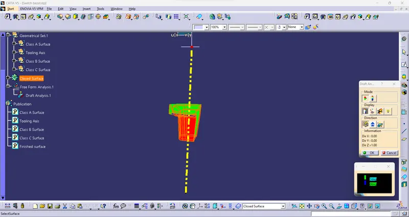
Top View:
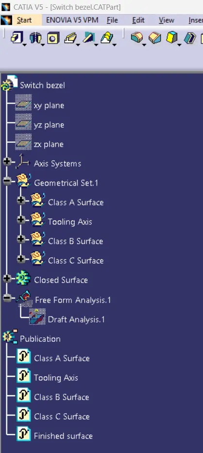
Tree :
- Maintain proper tree structure.
- The yellow icon is surface modeling.
- The green icon is a solid part.
- The publication highlights the shortcut.