Hood design-Week 2
HOOD DESIGN
AIM
A detailed report about the hood design which includes a detailed explanation about hood and its components, latch trajectory, mastic date, emboss definitions, manufacturing process like Deep-drawing and hemming and all the parameters followed in the design.
INTRODUCTION
Hood or bonnet is a main component of car. It uses to cover an engine room and protect about pedestrian safety and improve look. Bonnets are designed to reduce air resistance as the air flows around the car. It is used to decorate the car and add luxurious look. The shape of the bonnet is made aerodynamic in order to minimize the air effect. Bonnet is generally used to access the parts easily such as radiator, engine and many other parts. In automotive world the weight optimization plays an important role.
Type of component
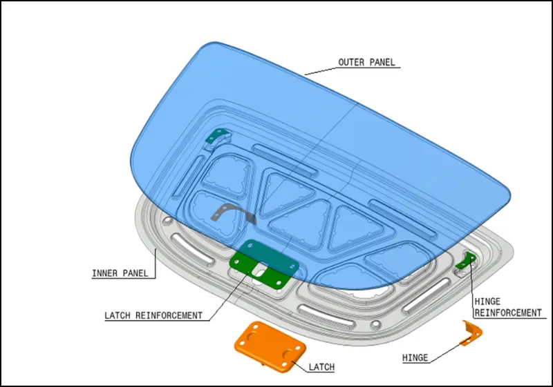
- Inner panel.
- Outer panel.
- hinge
- Latch & striker.
- rainforcement.
Outer panel
Outer panel is a stylish skin for a vehicle to improve vehicle look and major selling point. Outer panel thickness is 0.75mm Max.
Inner panel:
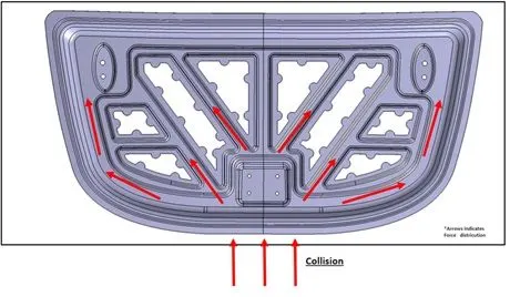
Inner panel is a boon of the hood. It mainly used to improve impact force distribution for an equally. The inner panel is designed in such a way that in case of collision, the impact force must go in outward direction, so that the impact on the driver and front passenger must reduce.
Hinge
Hinges are used to support to hood open and close purpose the hinges are mounting to weld process the hinges are mounting to inner body and its thickness is 0.75mm and hinge reinforcement are small parts so its made by 1.5mm.
Latch
Latch are used to hood/bonnet lock purpose this latch is design 0.75mm thickness and its reinforcement are 1.5mm.
Hood supports
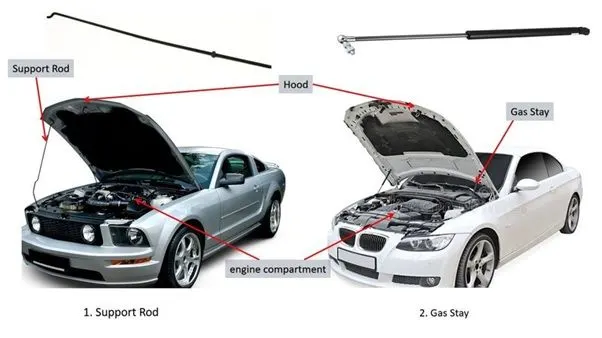
- Support rod.
- Gas stay.
- Support rod.
Support rod are normally used for most of the vehicle its cost effective and simple design. It used for automotive engine hood is arranged to be opened for the purposes of inspecting the engine room replacing the coolant, oil, and battery and engine service and maintenance purpose.
Design factor to be consider
- How I position supporting rod.
- Over the hood and mounting engine compartment.
- Create the supporting rod layout.
- Confirm where it’s mounting.
- Where opening angle and closing angle.
- Where my mount this and dis mount this.
- Length of rod define most be an opening angle.
Supporting rod shape
Supporting rod shape are based on structure.
Confirmation layout condition of supporting rod
- Input hood hinge CTR coordinate and the point should be a point A.
- Input opening angle of hood.
- Rod installation position is in Rignt hand side of the body fixed point and rod hooking hole is in the same side of coordinated in straight line. This is standard used to battery is assembling and maintance and easyly access the engine room.
- Avoid Supporting rod to much of curve to design. Maximum curvature is can’t exceed 35mm. (it’s not standard value based on experience).

- Gas stay
Gas stay are used to mostly luxury vehicle and SUV and mostly used for hood weight. And its less man power required. It is a similar part to access the hood.
It mounted inside hood or outside hood and it is used to access the hood less quick and easy.
Design factor to be consider
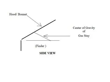
- To understand center of gravity based on the gas stay mounting.
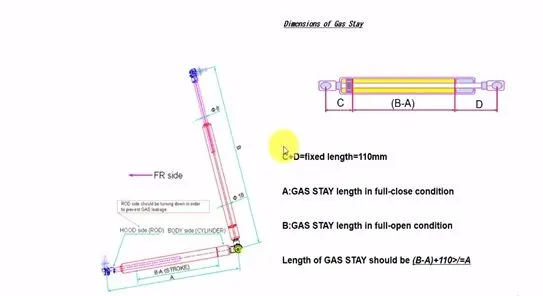
Dimension of gas stay
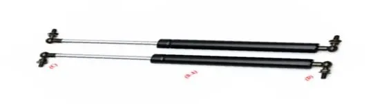
C+D =Fixed length.
A= Gas stay opening condition in full close condition.
B = Gas stay length in full open condition.
Length of Gas stay should be (B-A) + (C+D) >/=A.
(B-A) based on length of the hood. Length changed about hood dimension.
Case study
- Hood length is really big.
- Weight of hood.
- Too difficult to access a hood.
Type of factor to be consider to developing the hood
- Head clearance criteria.
- How to open and close hood.
- NVH (Noise & vibration harshness)
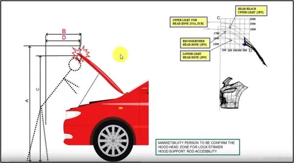
Head clearance criteria
Head clearance is decided upon the region or country regulation. So some vehicle are designed for different country regulation for opening and closing position.
The distance C and D shown in the image is represented as graph in the upper right corner of the image. Choosing the right head zone position will decide upon the angle of the hood opening. Hood developing engineer will be consider a regulation between vehicle are selling which market (Head clearance criteria diagram).
Standards
Head clearance criteria standard are base between the human average height. When the hood open and closing time human head will be hitting the hood so avoid the un wanted accidents and visibility and accessing the engine bay etc.,
- Japanese standard.
- European standard.
- American standard.
Head clearance criteria.
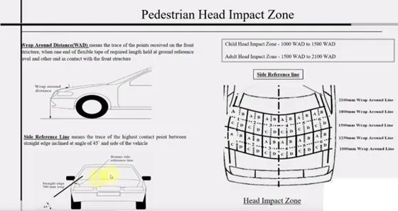
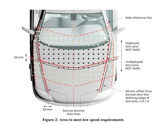
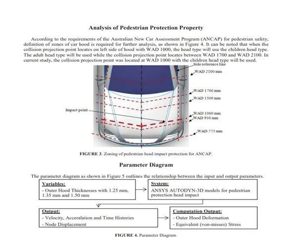
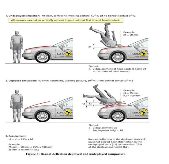
Euro-NCAP Wrap Around Zone
Wrap Around Zone
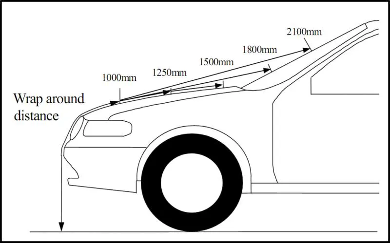
When a car crashes on the pedestrian, the whole human body wraps around the front shape of the car and the head impacts on the bonnet or the wind screen distance on human head impacts on the vehicle.
To be specific the wrap around distance is a measurement of the Euro-NCAP from ground to hood impact zone between change to adult and child.
Wrap around distance between during accident pedestrian how to react to hitting the hood to consideration. This factor will be considering material type and speed of the vehicle and area of impact this factor will be considered. The European NCPE department regulate the standard about the warp around distance.
- Child impact zone between 1000 to 1700mm.
- Adult impact zone between 1700 to 2100mm.
Hood side wrap around distance
Hood side potion wrap around distance are two types
- OPEL ZAFIRA – Inlaid Hood.
- OPEL CORSA – Wrap Around Hood.
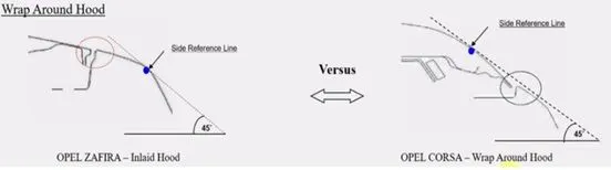
Wrap around hood side reference line from the ground taken 45 line is touch as and point of BIW side body.
NVH (Noise & vibration harshness)
Euro-NCAP.
Mastic date
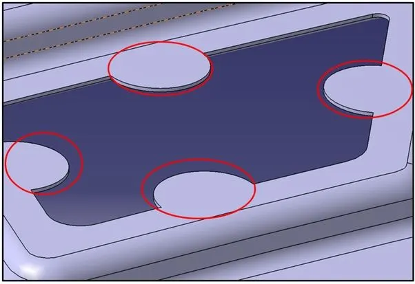
- It is basically an NVH topic mastics are point / surfaces given on embosses for applying mastic sealant to join outer and inner panel and also give good value of NVH.
- So mastic sealants are joining material used to join inner and Outer panel and at the same time reduces the NVH value.
- One spot of mastic sealant provides strength locally at around 80 mm so we need to put these mastic points in such a way that it covers the most of the hood region except reinforcement area of latch and hinge because that alone provide good NVH so no worries there.
- Here I have spotted points where I have applied mastic data when mastic sealant will be applied and while undergoing hot bath it gets hardened & make the joint strong.
- designing inner panel one must take care of spaces to provide on panel for latch and hinge.
- We use mastic sealant because we cannot provide spot welding on outer panel as it won't look good from outer side and car’s aesthetic will compromise in doing so.
Hood designing using UG-NX
Outer panel
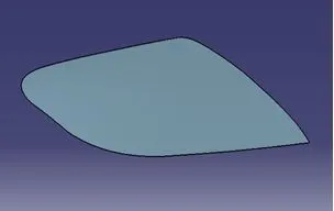
Outer panel will be developed styles team or benchmarking-1 or parent vehicle design also considered to develop hood as per latest standard. Then provide hood development team to develop hood inner panel.
Inner panel
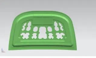
Inner panel supports outer panel. It consists of different embosses and hole at different places. Embosses provide stiffness as well as dissipate energy towards hinges. To determine the most effective position of hole, the method of model siffness is employed. Inner panel is offset of the parent work surface. Inner panel thickness is 075mm.
latch and striker with reinforcement
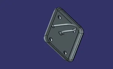
latch system ensures that the hood stays locked, therefore protecting the engine and the many other parts that reside within the hood of the car. hood should not swing open at once, and therefore, a safety hook must be present to catch the unlocked hood and keep it closed.
hinge
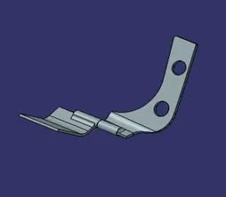
The active hinge must lift up the rear part of the bonnet in appropriate short time to extend the deformation space between the bonnet and the rigid parts of the engine compartment. Fast and controlled lifting of the bonnet mitigates the consequences of collision between pedestrian and a vehicle.
Latch and hinge arrangement
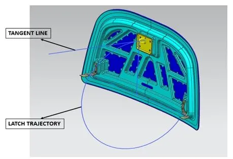
- The latch should be placed at appropriate position so that it does not become a obstacle while the hood is opened and closed. For this purpose, it should be placed perpendicular to the hook.
- To achieve the above condition a line will be made using the axis of the hinges on the opposite ends. About the midpoint of this line a datum plane will be made and then a sketch will be on this datum plane.
- Inside the sketch a circle will be made which will indicate the trajectory of the opening and closing of the hood and then a line will be made which will exactly position the latch at appropriate position.
- A tangent line will be made on the circle which will touch with the previous line.
- Another straight line will be sketched on the latch which would be perpendicular to the latch.
- Now both the straight lines will be coincided with each other using the align feature in the assembly workbench. By doing this the latch will get arrested perpendicularly and will follow the the circular patch so that the hood can be easily opened and closed.
- The above image shows the procedures performed to place the latch at appropriate position.
Manufacturing process involved in making different features of the sheet metal
Deep Drawing
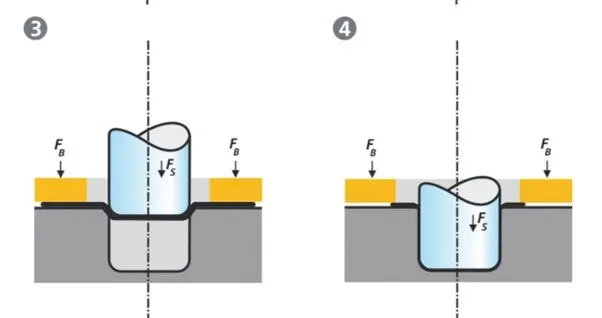
- The deep drawing process is a forming process which occurs under a combination of tensile and compressive conditions. A flat sheet metal blank is formed into a hollow body open on one side or a hollow body is formed into a hollow body with a smaller cross-section.
- Deep drawing processes are divided into three types:
- Deep drawing with tools
- Deep drawing with active means
Deep drawing with active energy
- In the automotive industry, deep drawing is usually carried out using rigid tools.
- The deep drawing operations is shown above
- The rigid tools consist of a punch, die and binder. In deep drawing, the plate holder closes after the metal sheet blank has been inserted.
- Next the sheet is clamped between the die and the binder. This process slows down the flow of the sheet while it is being drawn and thereby prevents wrinkles from forming under the binder. The punch stretches the sheet over the die radius and forms it in the die. The amount of punch force necessary for forming is thereby continually increased up to the lower dead centre of the punch.
- Whereas in pure deep drawing there is no reduction of sheet metal thickness, forming is achieved in stretch forming purely as a result of a decrease in sheet metal thickness. Stretch forming is extensively used for the forming of only slightly curved parts with low depth of draw (e.g., roofs, doors).
- When drawing complex car body parts in practice, there is usually a combination of stretch and deep drawing involved. It is necessary that the sheet metal is stretched as well as possible without reaching the material’s limits (e.g., splits, wrinkles).
Hemming
- Hemming is a forming operation in which the edges of the sheet are folded or folded over another part in order to achieve a tight fit. Normally hemming operations are used to connect parts together, to improve the appearance of a part and to reinforce part edges.
- In car part production, hemming is used in assembly as a secondary operation after deep drawing, trimming and flanging operations to join two sheet metal parts (outer and inner) together. Typical parts for this type of assembly are hoods, doors, trunk lids and fenders.
- There are various types of hemming operations:
Conventional die hemming
Roll hemming
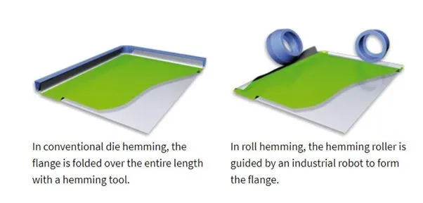
Conventional die hemming
Conventional die hemming is suitable for mass production. In die hemming, the flange is folded over the entire length with a hemming tool. Normally the actual hemming is a result of a forming operation in which the flange is formed with a hemming tool after the drawing and trimming operations have been completed. The formed flange is then hemmed in several process steps. These steps include, for example, the pre-hemming and final hemming depending on the respective opening angle of the flange. Production plants for conventional die hemming are very expensive, but the cycle times are very low.
Roll hemming
Roll hemming is carried out incrementally with a hemming roller. An industrial robot guides the hemming roller and forms the flange. Roll hemming operation can also be divided into several pre-hemming and final hemming process steps. Roll hemming is very flexible to use and tool costs are significantly lower as compared to those of conventional die hemming. However, the cycle times are much higher since the hemming is realized using a hemming roller which follows a defined path.
Conclusion
Hood will design based on parts and design requirement, technical specification and safety requirements. This all basic and parent vehicle date and new idea and various standard will be Consider to design a hood.