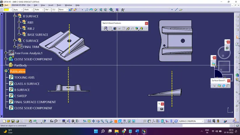
Week 8 - Challenge 1 - Base Bracket Design
TOOLING AXIS:-
A tooling axis is the direction of a component where the component is easily ejected from core and cavity.
A tooling axis is a most important for removing material with very finished surface. Before start working in any component it is needed to create a tooling axis firstly.
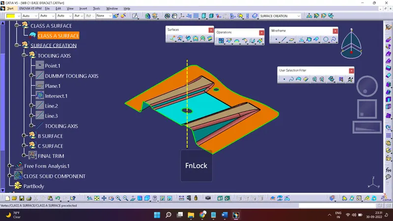
Creation of tooling axis:-
Most probably the bisecting method is used for creation of tooling axis.
First of all need to analyse a component for best tooling axis.
Now create a dummy tooling axis by using a point and line(It will dummy tooling axis).
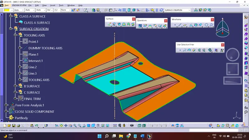
Create a plane in a other direction After that create a intersection between a plane and a component .
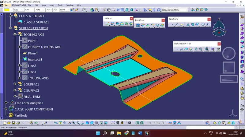
After getting intersection line create a line which have angle.
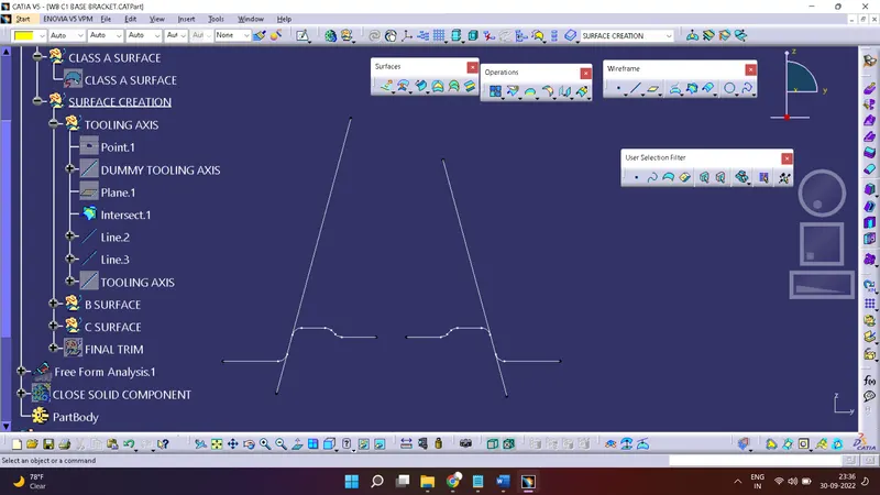
now create a line by using a bisecting of two line.
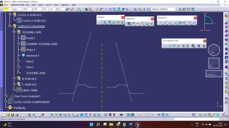
This yellow-green will be your final tooling axis.
DRAFT ANALYSIS:-
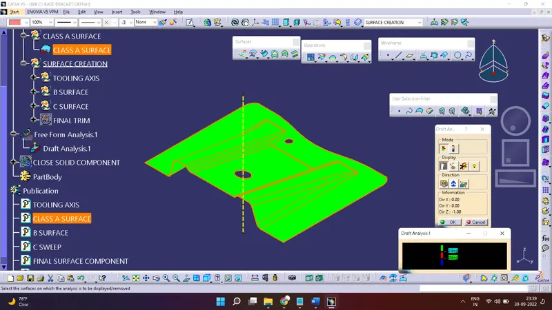
A draft analysis is helps to detect a angle of a component. it will be easily removed. In catia a draft analysis is performed based on colour rain identify zones Using a draft and by using a draft analysis we can verify taper angle.
Examine angle change with a face as well as look at what time line and injection surface in parts
A draft analysis help to give a proper draft angle
Draft angle describe the amount of taper of mould which perpendicular to the party line
Minimum draft angle is required 3 degree.
DRAFT ANALYSIS of class A surface
Creation of class B Surface:-
First of all find the different different surface like base, ribs & start working one by one.
1. Extract the Surface
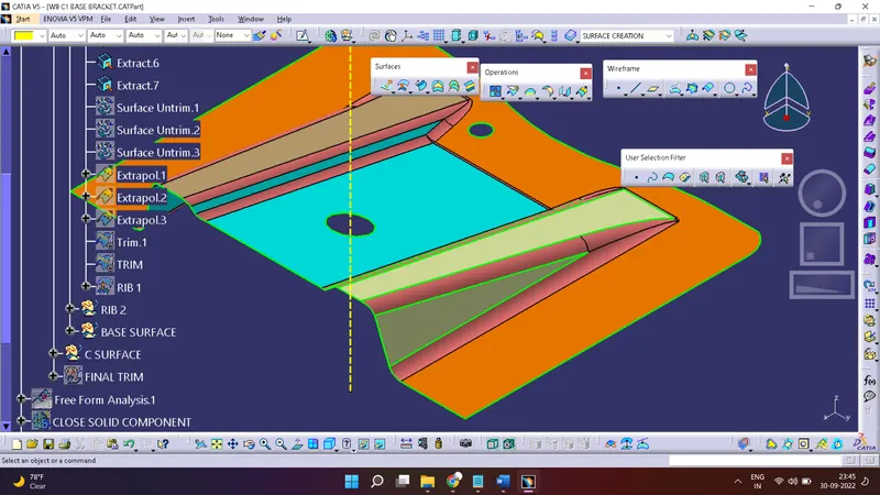
2. Untrim the all surface
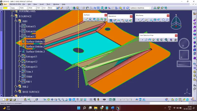
3. Do Extrapolate for increase length/width of a surface
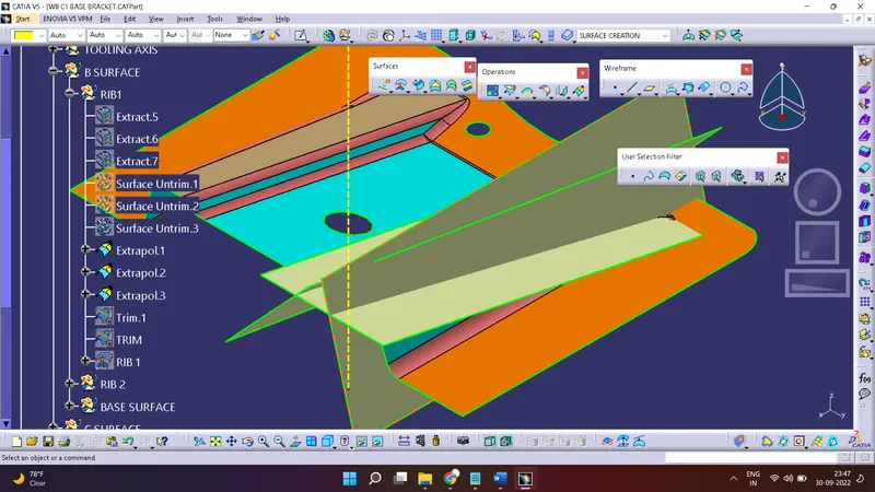
4. take only usable Surface & Trim it all. then offset Surface 2.5 mm
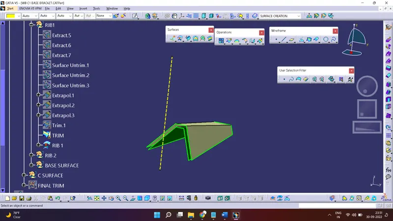
5. Do Same Procedure for all surface of component
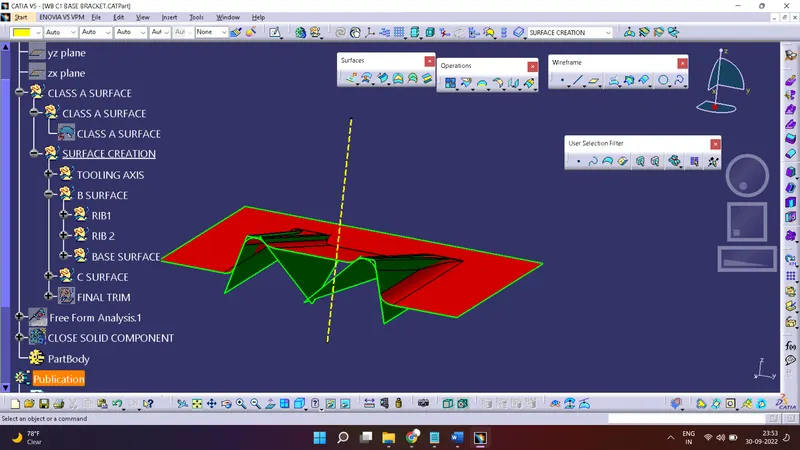
6. Final B Surface
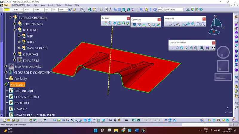
Creation Of C Surface:-
Firstly Create a Boundary by using a class A surface and sweep it with tooling axis direction
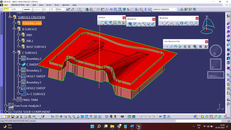
Hole Sweep
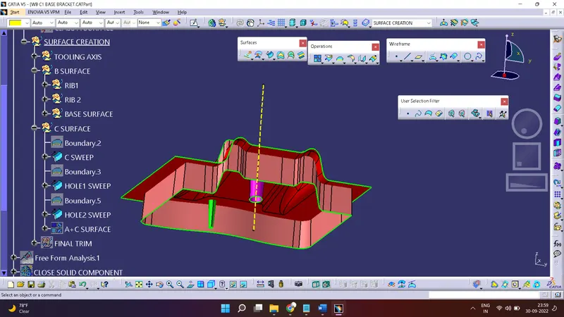
C Surface Created.
Joining of Class A & C Surface:
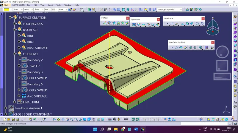
Joining of Class A & C Surface with B Surface: & Get final Surface Component:
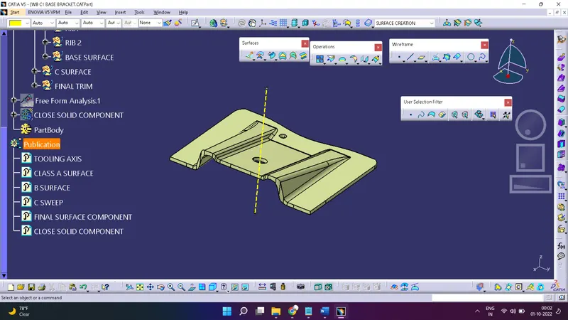
Creation Of Close Solid Component:-
Goto Start>Mechanical Design >Part Design
Here Use Surface Creation Toolbar >Close Surface for create a Solid Component
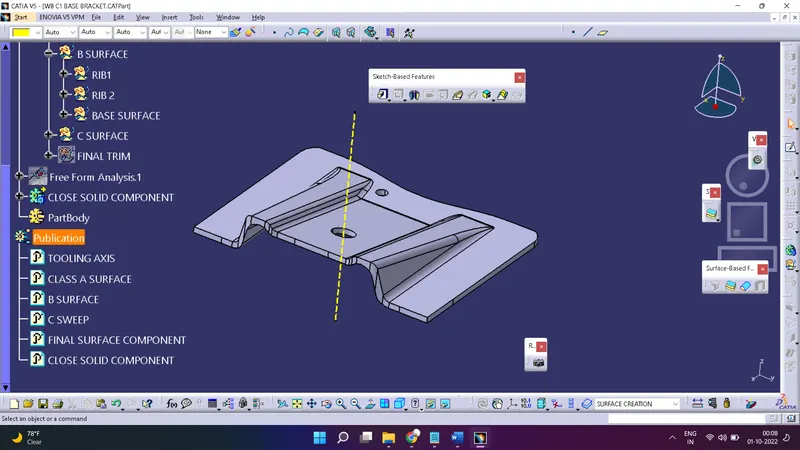
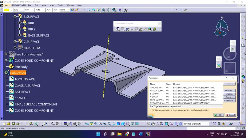
Creation Of Publication:-
Goto tools> Publication
Select Component which need to Publish then OK
Different Views Of Component:-