Week 8 - Challenge 1 - Base Bracket Design
Create the Base Bracket Plastic component through the given Class-A surface. To begin with, the tooling axis for the given Class-A Surface should be created meeting the requirements of the draft angle and at the end perform the Draft analysis on the model.
SOLUTION:-
Screenshots of the Draft analysis report for both the given Class-A surface and the final plastic component
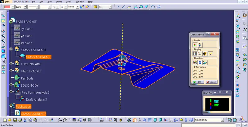
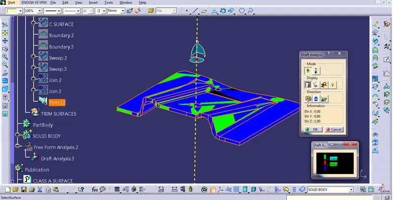
ISOMETRIC VIEW
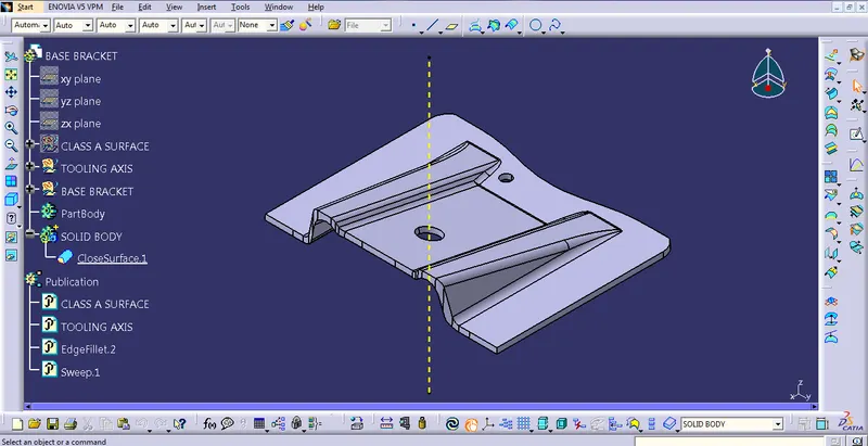
FRONT VIEW
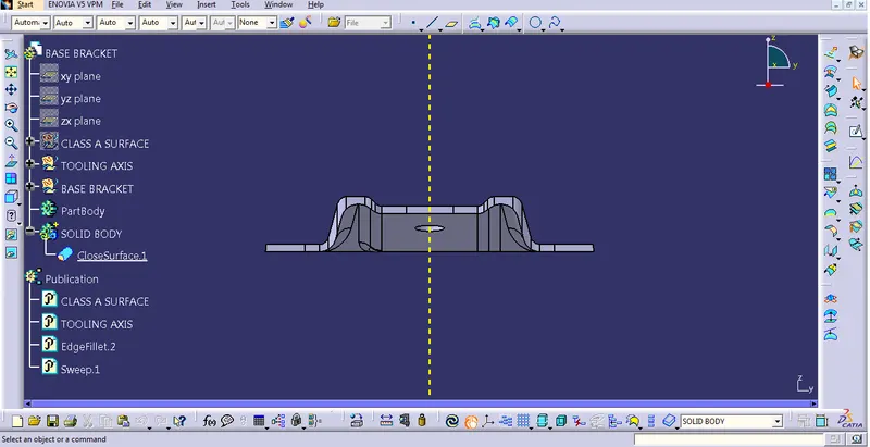
SIDE VIEW
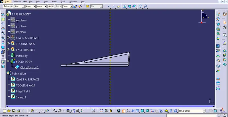
TOP VIEW
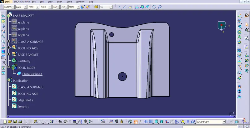
A detailed report should be done explaining the draft analysis
Draft Analysis is the process in which we can decide whether the class A surface is perfect for moulding or not. The standard draft required is a minimum of 3 degrees in the plastic industry. To check that, we have to create a tooling axis with the help of the given class A surface.
An explanation should be given on the way of creating the tooling axis, particularly the Bisecting method.
We can create the tooling axis by using two methods. Either using a flat surface or with the help of Bisecting line method. Here in this example, I have used Bisecting line method in which we have to create a bisecting line with the help of two intersecting planes.
First of all, create an intersection in class A surface with the help of Intersect command. Then create a centre line in the x plane and then in the y plane with the help of intersecting sketch. Then with these 2 lines finally we get bisecting axis which is the tooling axis in which the core will move upward and downward.