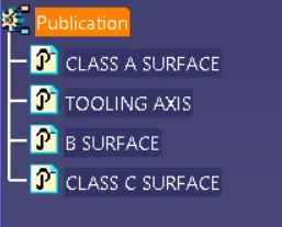
Week 8 - Challenge 1 - Base Bracket Design
BASE BRACKET DESIGN
Objective -
Create the Base Bracket Plastic component through the given Class-A surface. To begin with, the tooling axis for the given Class-A Surface should be created meeting the requirements of the draft angle and at the end perform the Draft analysis on the model.
Important Points -
Class A surface - It is an automobile's outermost surface that gives a vehicle an aesthetic look. It is physically touchable. It is obtained from day modeling by reverse engineering. This surface is given input to the plastic product designer to work on.
Class B surface - This surface is created by taking an offset from the class A surface. It is a surface on which all engineering features like screw bosses, dog house, ribs & mounting are created.
Class C surface - This is a surface that joins class A & class B together.
Tooling axis - It is the direction in which the core & cavity open & close.
Method followed -
- Checking continuity of class A surface.
- I am creating the Tooling axis.
- Performing draft analysis.
- Creating Class B surface from given class A surface.
- Creating Class C surface to join A & B class surface.
- Creating a solid feature by using a closed surface.
- Checking continuity of given class A surface-
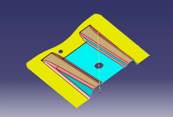
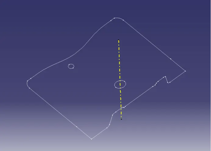
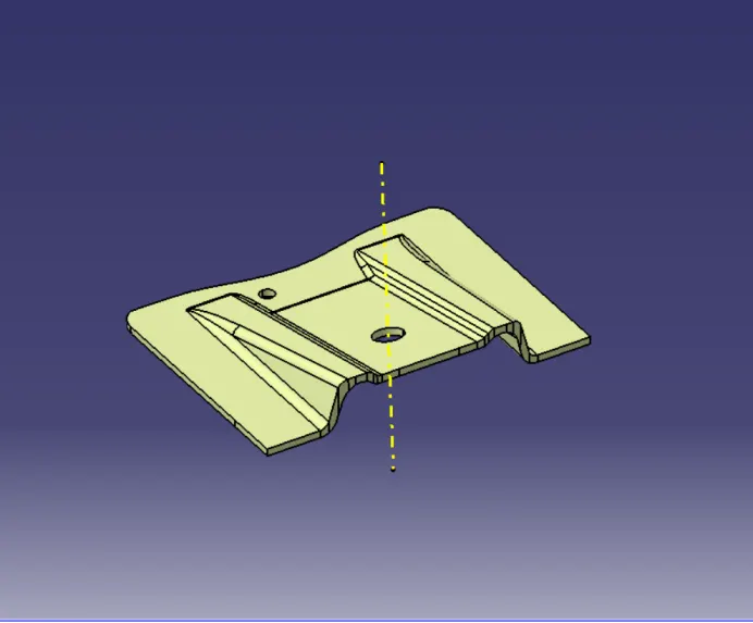
First of all, we have to check the continuity of the given class A surface to ensure class A surface is properly joined or that no discontinuity is present. This can be done using Join or Boundary command in CATIA. By looking visually at the image below we know that the surface has a continuously connected boundary as highlighted by green light.
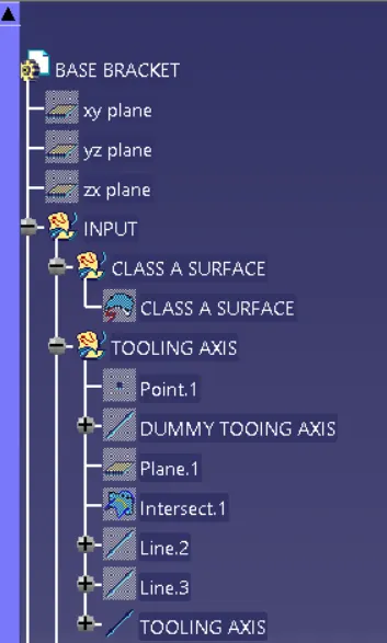
- Creating tooling axis -
The next step is to decide the tooling axis direction. Analyzing the model visually to see which direction is most suitable for the tooling axis. From the below image it is seen that the surface has two holes at its top.
So Z direction as tooling axis clear top holes in tooling direction as well as flat surface & this is dummy tooling axis as shown in below image, To create dummy tooling axis, insert point at the top hole center & draw a line along Z.
Now we will use the bisecting method to find the real tooling axis. To create a tooling axis in Z- the direction, create a plane parallel to the YZ plane & passing through the reference point. Take the intersection of the YZ plane with the class A surface. We will get the two curves.
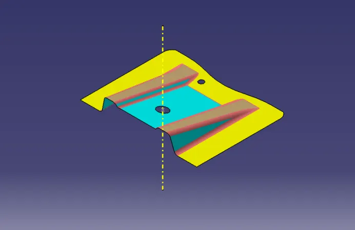
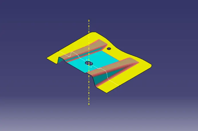
Now using the line feature create a bisecting line using the two lines.
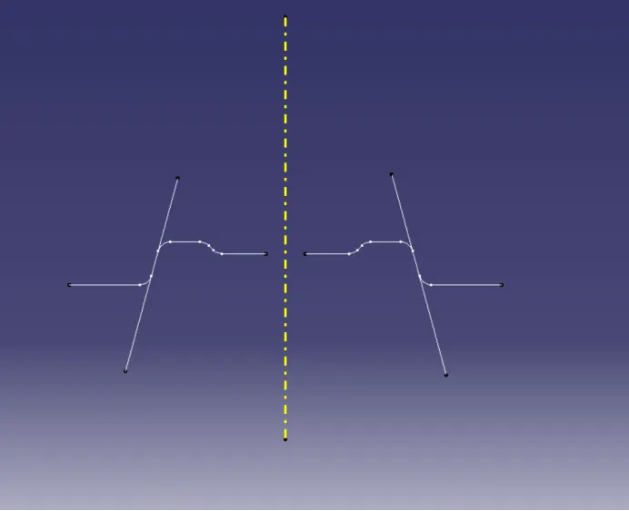
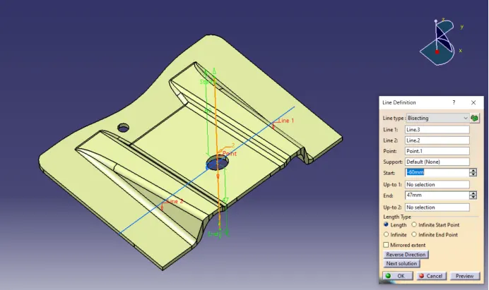
- Draft analysis -
To perform draft analysis, Go to the insert > Analysis > Feature draft analysis.
Switch customize view parameters and select material.
Click on the compass icon and align it with the tooling axis & click on the surface, we will get our results.
From the below image we can see that the surface in green color has a more than 3° draft which is most required for tooling feasibility. Also, see the color variant display box.
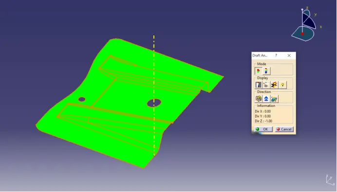
Draft Analysis Views -
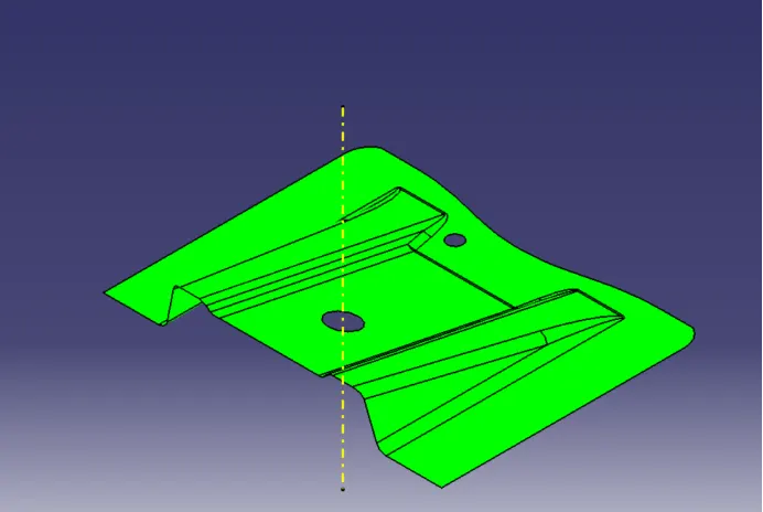
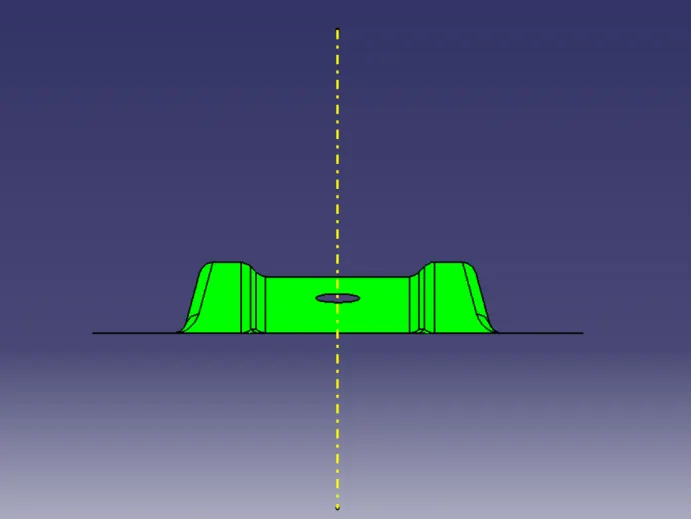
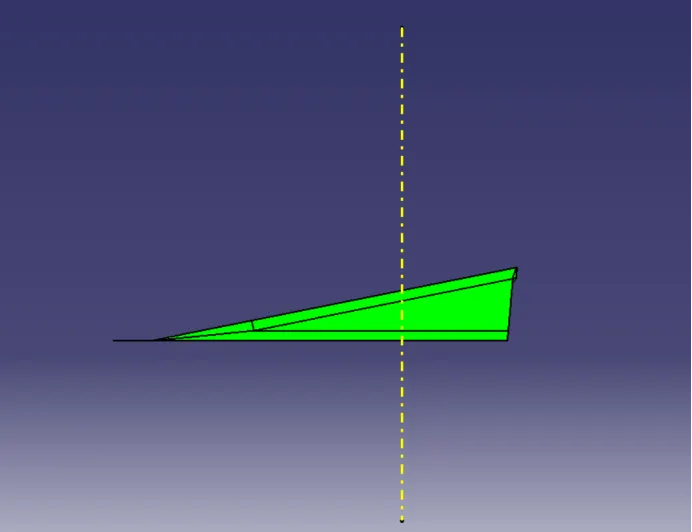
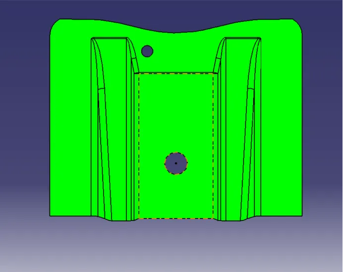
- Creating class B surface from given Class A surface -
We extracted the Class A surface and worked on it separately to create the Class B surface.
- Rib 1
- Rib 2
- Slant surface
- Flat surface
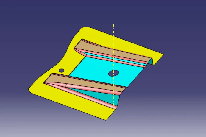
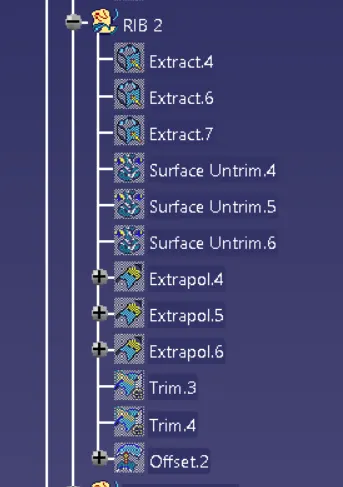
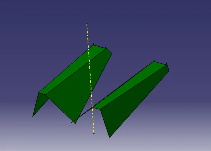
- Rib 1 & 2 -
- Extract the flat surface.
- Untrim the surface
- Extrapolate it.
- Trim all three extrapolates
- Offset it by a 2.5 mm distance to the downward.
- For both ribs follow the same procedure
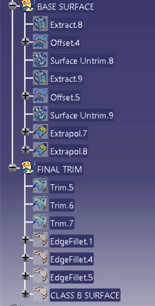
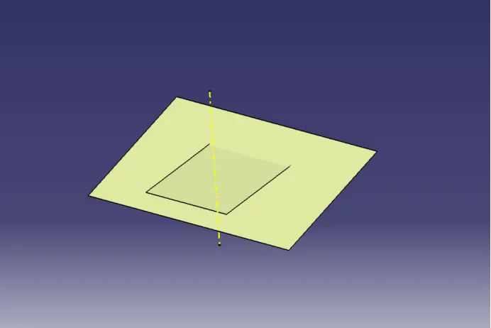
- Slant surface and base -
- Extract the flat surface.
- Offset it by a 2.5 mm distance.
- Untrim the surface
- Extrapolate it by 10 mm
After offsetting all the surfaces, we have to trim these surfaces together to get our final class B surface.
Final Trim: While trimming follow the exact shape of the Class A surface.
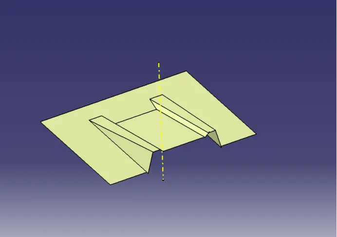
The final trim surface is our inner surface of 2.5mm offset so give fillet edges as per the formula,
Fillet Edge: Class A surface Fillet radius + Part thickness
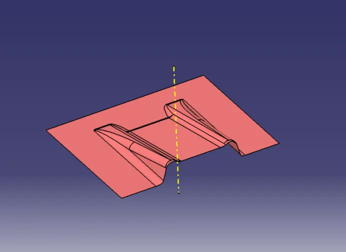
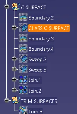
- Creating Class C surface to join A & B class surface -
Extracting class A surface and edges of the holes
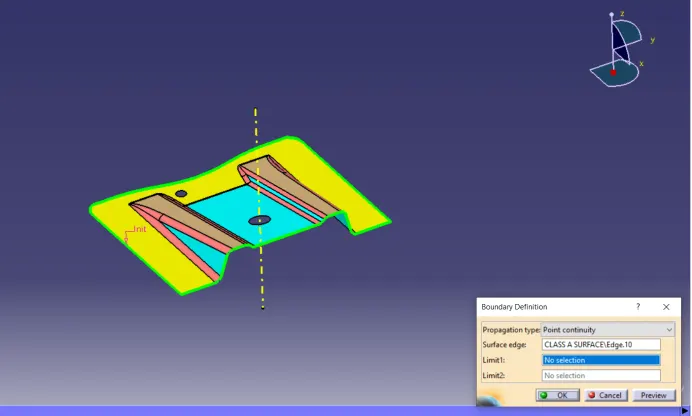
Sweeping the boundary of the class A and holes with the use of draft direction then select guide curve and draft direction and give a 3-degree draft.
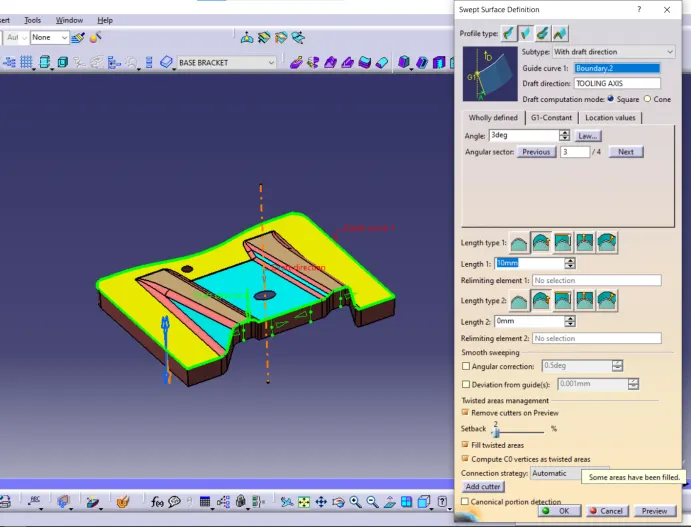
Join both the Class A and Class C surfaces together.
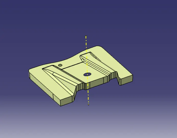
After joining, trim the joined surface with the Class B surface.
- Creating a solid feature by using a closed surface -
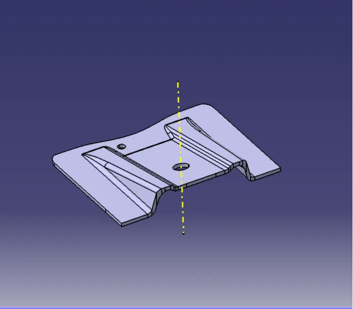
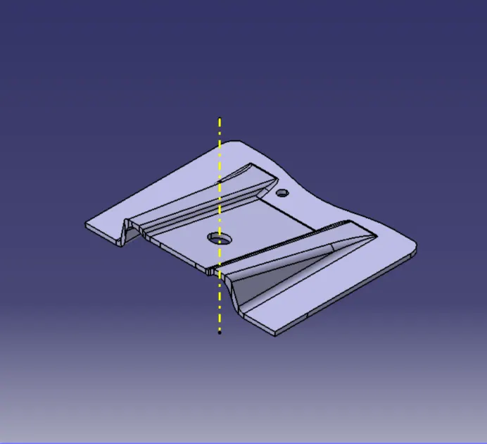
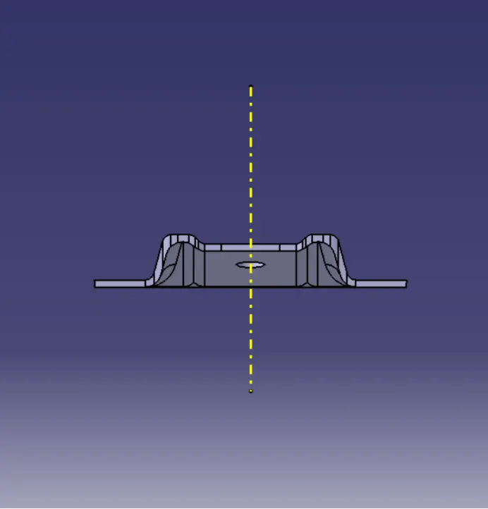
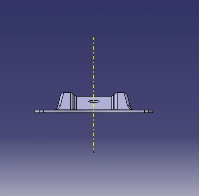
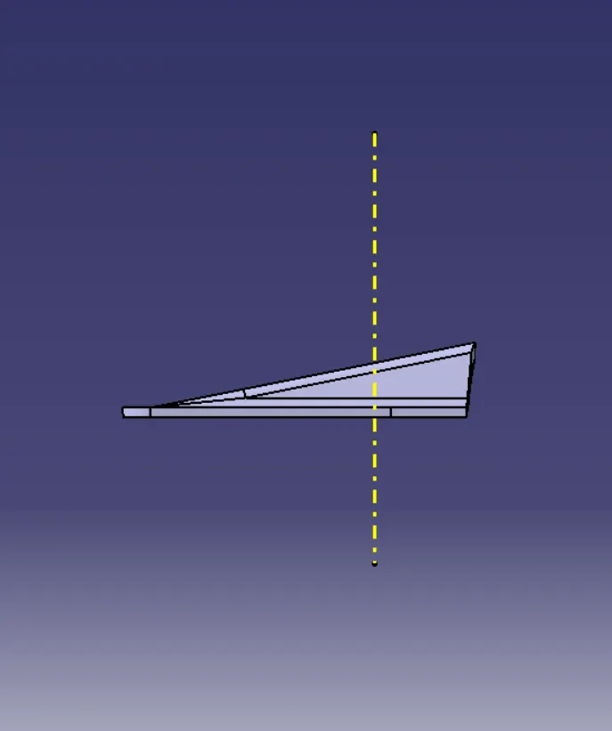
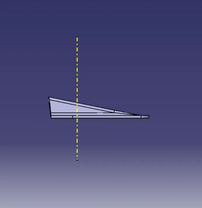
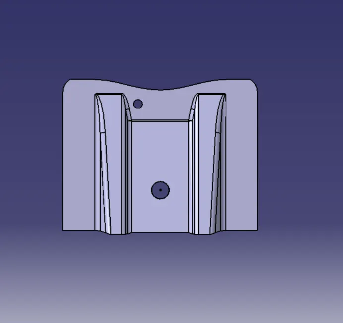
A solid body is created by a closed surface feature in the Part Design workbench in the defined part body. This is our design output shown as given below in various orientations.
- Views -
Feature Tree -