Week 8 - Challenge 1 - Base Bracket Design
REPORT OF BASE BRACKET
Aim:
To create the Base Bracket of Plastic Component through a given input Class A Surface and Tooling axis to Draft Analysis on the A surface and final plastic component.
REPORT:
BASE BRACKET:
Class A Surface:
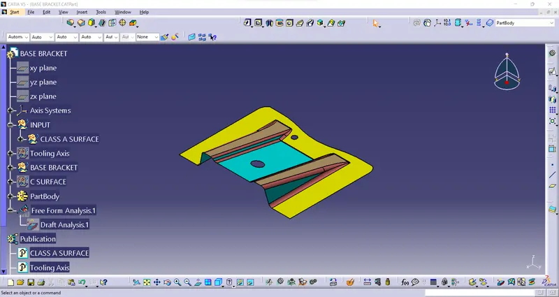
- This is a Input Surface to make a Solid part of a Plastic Component, This is the base to make a plastic body.
- To continue with the design process first we need to find out the tooling axis for the surface and check for all the drafts using the Draft Analysis tool in CATIA.
- And Publicize the A surface.
Tooling Axis:
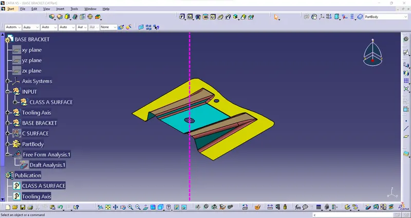
- Create a point with the ‘circle/ sphere/ ellipse’ reference and make it as Isolate and double click on the point change explicit to coordinates.
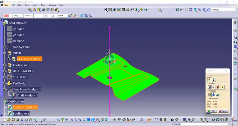
- Create a Line - Point To Direction click on the point and take a reference as Z axis and give some color and make it a dashed line.
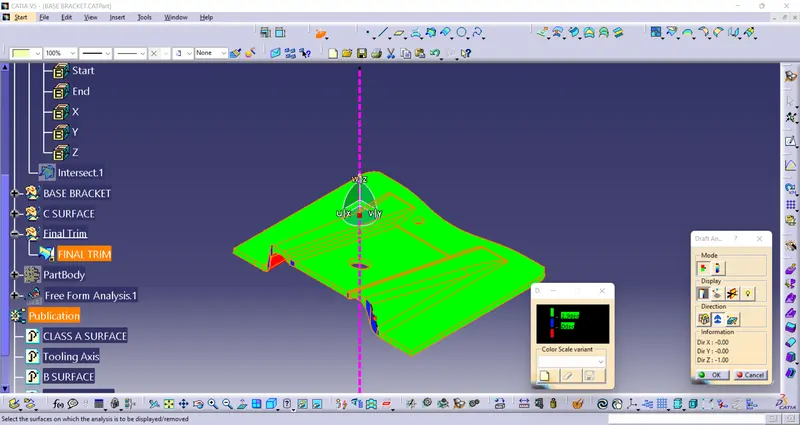
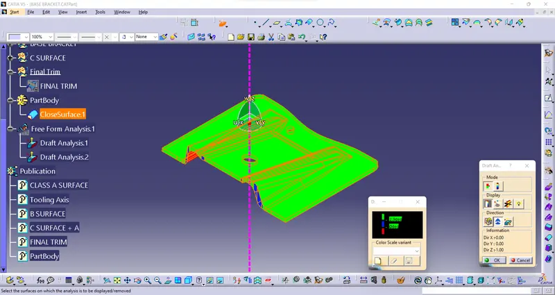
- Take a draft analysis with A surface in positive it’s fully green.
- And same thing check with Final analysis in finished solid component it’s seems little deviation in blue color that’s fine.
- And Publicate the Tooling Axis.
Class B Surface:
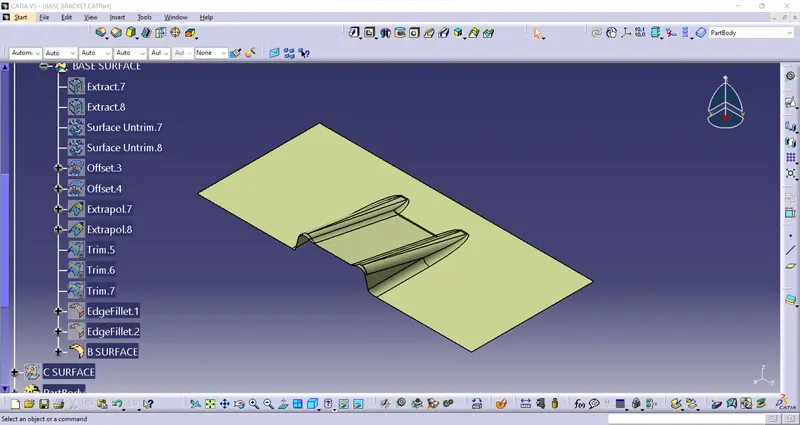
- Offset the A Surface And Untrim it after extrapolate it and give the fillet radius measure from A surface or Intersect the A surface to Find it to apply the 3mm + 2.5mm of the length.
- Then Publicize the B-Surface.
Class C Surface:
- Unhide the A Surface to Take a boundary as a reference to make C surface.
- Go to sweep line-> with draft direction 3 deg draft angle downward outside.
- And Same thing to do for the 2 holes.
- Join all of them to make C Surface.
- Then Publicize it.
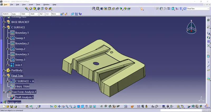
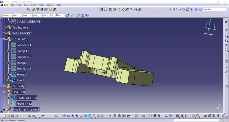
Final trim:
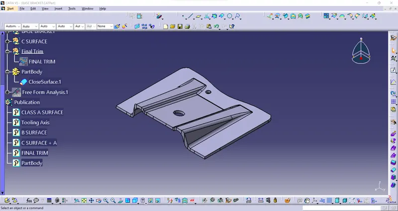
- Take a Joined part C Surface And B Surface to Trim unwanted surfaces to make it as a Solid part.
- Then Analyze the Draft with the final part It Seems little Deviation in blue that’s fine.
- Publicize it.
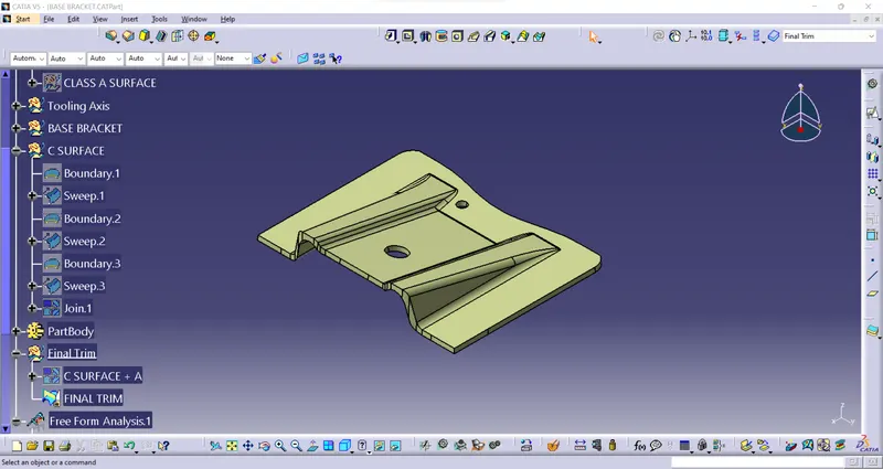
Part Body:
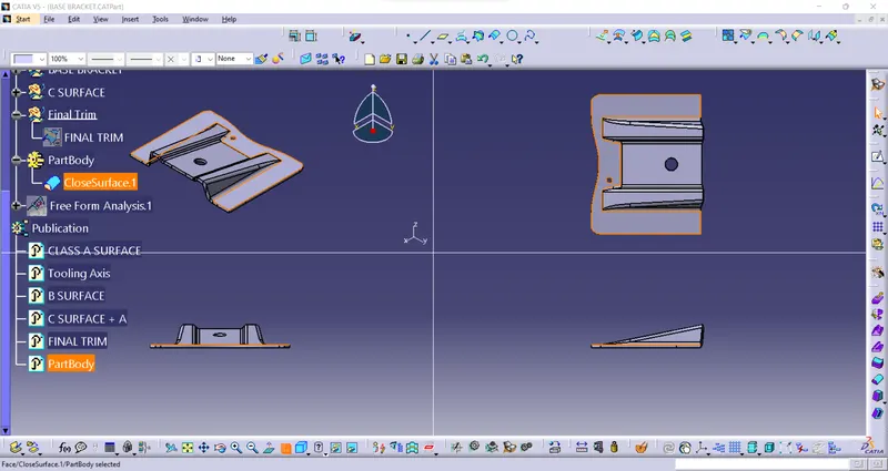
- Take the final trim to a solid component and took a Draft Analysis it seems little deviation.
- Then publicize it.
Conclusion:
The Given procedure of the report is Done Properly.