Week 8 - Challenge 1 - Base Bracket Design
AIM
To create a base bracket plastic component given class A surface.begain with tooling axis and draft angle analysis.
PROCEDURE
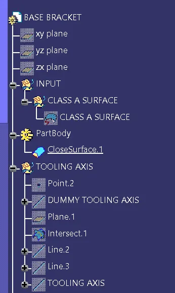
first we have import the class A mlodel CATIA V5 file
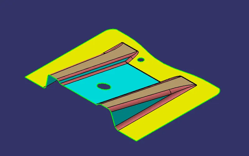
next we have findout the direction to create the dummy tooling axis.
after findout the direction to create the dummy tooling axis by using point and plane.using intersection command to create intersect with respective directions.
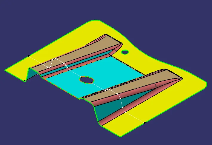
to create supporting lines along with directions using point and point direction after creating supporting line we have create bisecting line with help of supporting lines.
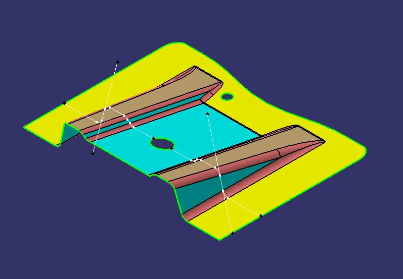
finally to create tooling axis and do draft analysis given class A surface.
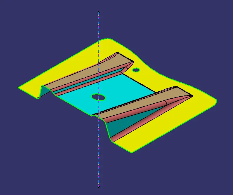
after create tooling axis next we have create draft analysis
we need to go insert and select feature draft analysis in feature draft analysis first use composs direction define new draft direction
set the draft angle 3deg.lock the direction and analysis the draft under running on surface.finally draft analysis on plastic base bracket is done.
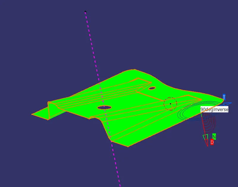
now we have create class B surface .thickness of class A surface is called class B surface.
B SURFACE
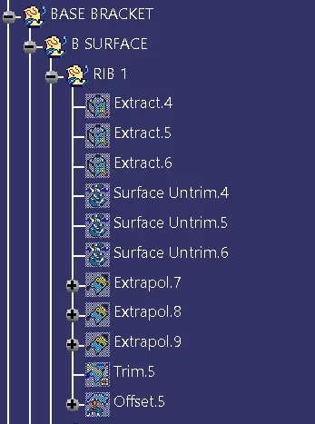
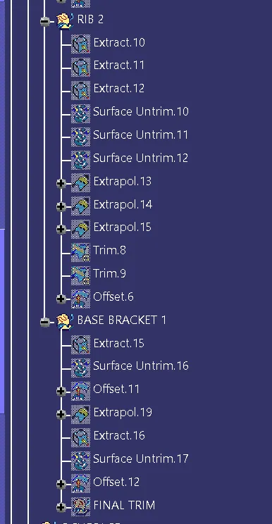
to crate geometrical set named as rib 1 extract the three surface and then untrimmed the extracted surface now we have extraplot the extracted surface and then trimmed.now offset the trimmed surface
with required thickness.now we create the rib 1 do the same procedure to create rib 2.base and inclined surface.
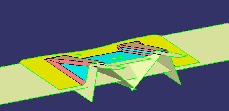
after creating the base surface apply fillets( after apply fillets measure the thickness of class A class B surface should be equal to thickness value )and we get the class B surafce.
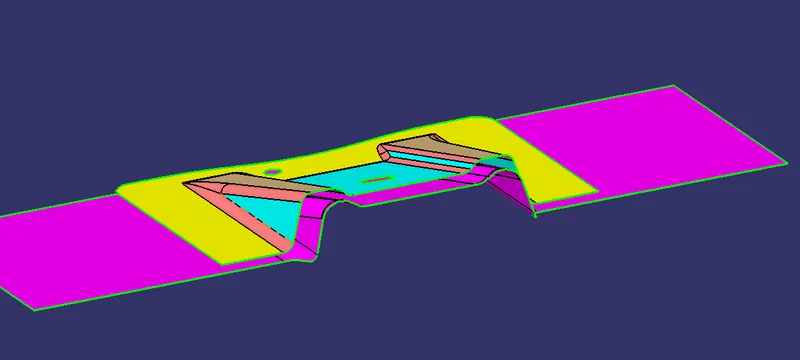
CLASS C SURFACE
after creating class B surface now we create the class C surface
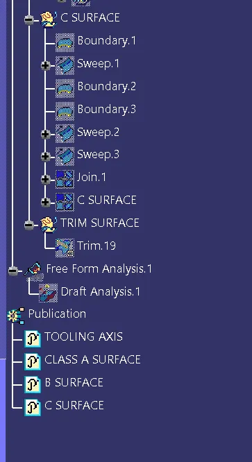
create new geometrical set nammed as c surface.first to create boundary by using boundary command and then select sweep command to create class c surafce in sweep command to choose draft and direction option guide curve 1 as boundary and draft direction as tooling axis.draft angle is 3deg.and than ok.do the same for holes now we create class c surface.
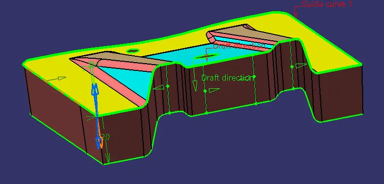
now jion the class A and class C surafce
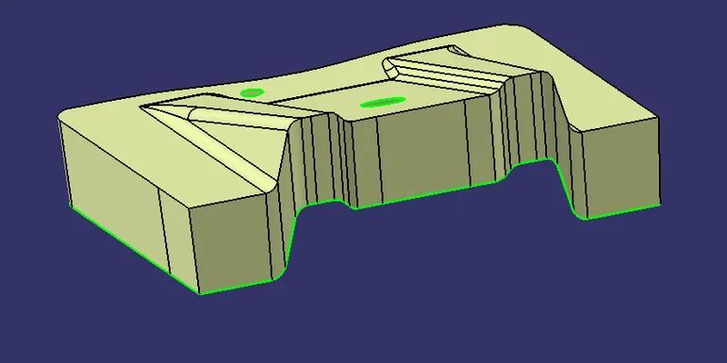
after joining the class A and class C surface trimmed with class B surface we get the base bracket surface model.
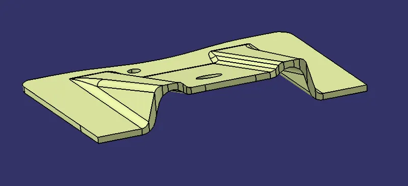
now we have create surface model to solid model by using closed surface option. we get complete solid part body
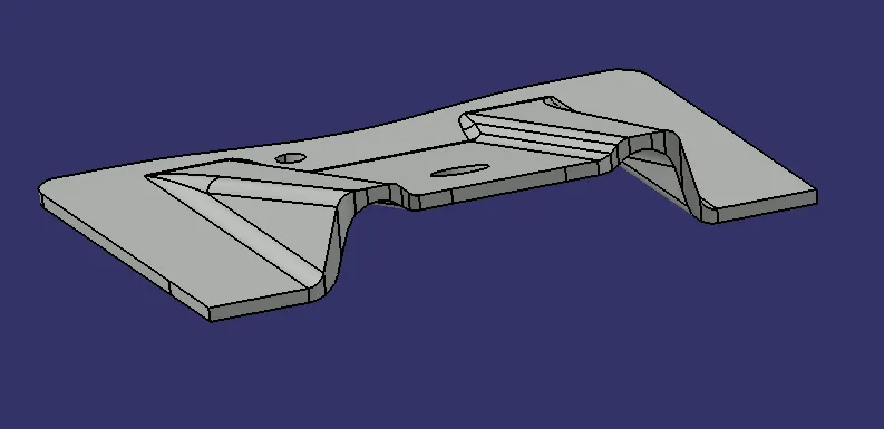
ISOMETRIC VIEW
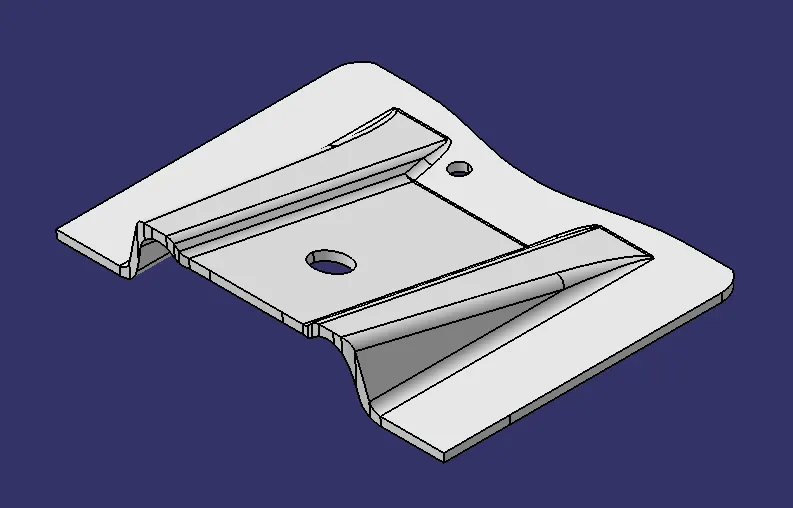
FRONT VIEW
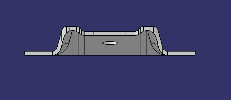
SIDE VIEW
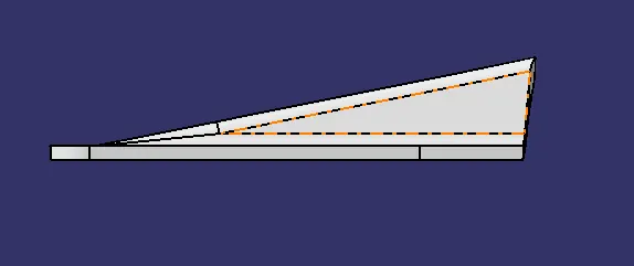
TOP VIEW
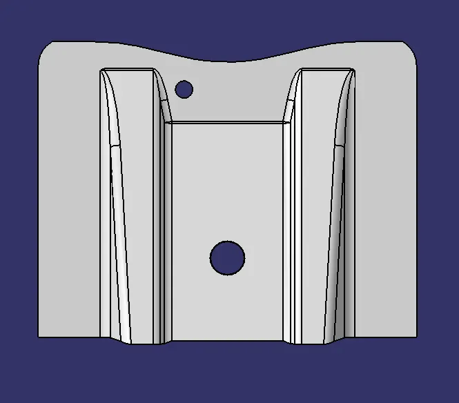
BOTTOM VIEW
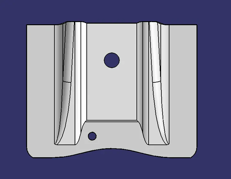
TREE STRUCTURE
CONCLUSION
we have successfully created solid part of base bracket given class A surface.and draft analysis .