Radar Mast & Final Assembly of Yacht
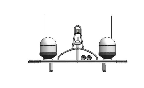
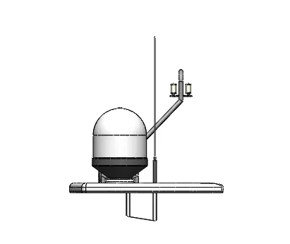
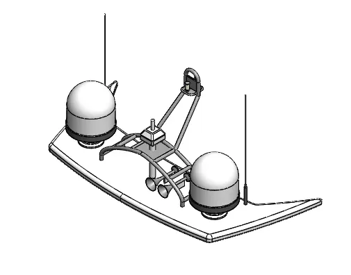
RADAR MAST
FRONT VIEW
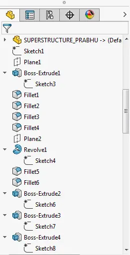
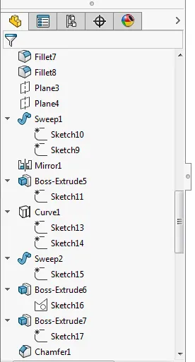
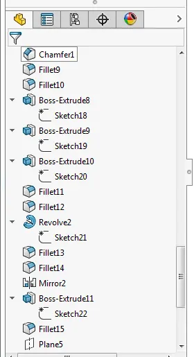
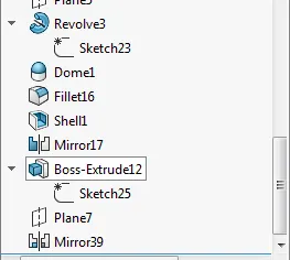
ASSEMBLY
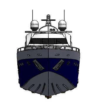
FRONT VIEW
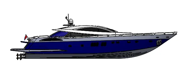
LEFT VIEW
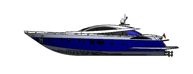
RIGHT VIEW
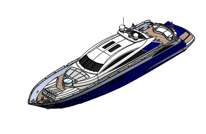
ISOMETRIC VIEW
TITTLE
SUNSEEKER PREDATOR YACHAT
AIM
To sketch and rendering sunseeker yachat.
OBJECTIVE
- To create and model external parts using solidworks 2016.
- To assemble the parts.
- To create phorealistic rendering by using photo view 360.
DESIGN MEDHODOLOGY
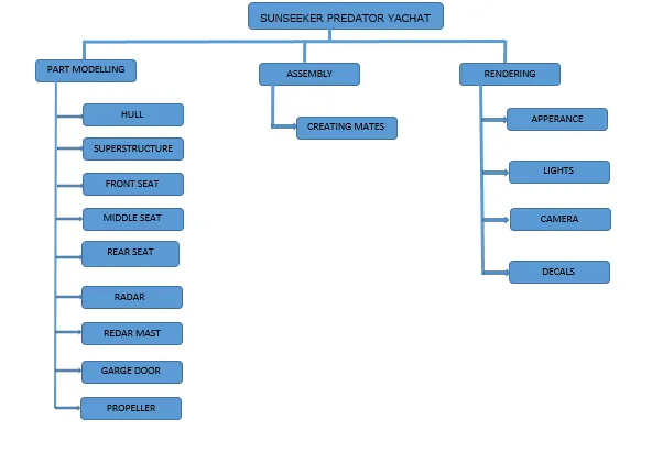
FLOW CHART
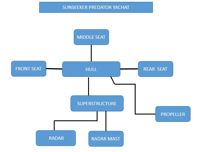
DESIGN AND MODELLING
COMMANDS IN SOLID WORKS
1.2D SKETCH:you can create drawing geometry using 2d sketch geometry only without reference to existing models or assemblies.the sktched geometry can be controlled by relations as
as well as parametric dimensions.
2.3d sketch
3d sketch tool create geometry by using points,lines,splines,and other sketchble shape to define a profile.
3.straight line
there are different varity of lines in solid works
construction line
to sketch a construction line
mid point line
to sketch a line a that is symmertical from the mid point of line.
4.circle
to create center based circle
perimeter circle
sketches perimeter based circle.
5.spline
there are two types of splines
b type splines
you can create b splines to create complex curves you can define and modify them using several controls including spline points,spline handle and control polygons.
style splines
based on Bézier curves, are a good option when it is important to have a smooth curve (that is, to assure curvature continuity). You define and control the curves using control vertices.
6. RECTANGLES
The loft feature is an important tool for (surface) modeling in SolidWorks. The loft feature creates a shape by making transitions between multiple profiles and guide curves. This tool is very valuable for modeling complex surfaces. You can do some really cool stuff when you use this feature properly.
23.KNIT SURFACE
Use the Knit Surface tool to combine two or more faces and surfaces into one. Note the following about knit surfaces: Edges of the surfaces must be adjacent and not overlapping. Surfaces do not need to be on the same plane.
24.TRIM SURFACE
Create two or more surfaces that intersect at one or more points, or create a surface that intersects with a plane or has a sketch on its face.
25.OFFSET FROM SURFACE
The Offset Surface tool creates a new surface body from an existing set of faces. The faces may be solid or surface faces.
26.EXTEND SURFACE
You can extend a surface by selecting an edge, multiple edges, or a face.
27.RULED SURFACE
The Ruled Surface command creates surfaces that extend out in a specified direction from selected edges.
28.DELETE SURFACE
You can delete faces from surface and solid bodies.
29.BOUNDARY SURFACE
The boundary surface feature lets you create surfaces that can be tangent or curvature continuous in both directions (all sides of the surface). In most cases, this delivers a higher quality result than the loft tool.
PART MODELLING DESCRIPTION
1.PROPELLER
A propeller is a rotating fan-like structure that is used to propel the ship by using the power generated and transmitted by the main engine of the ship.
The transmitted power is converted from rotational motion to generate a thrust which imparts momentum to the water, resulting in a force that acts on the ship and pushes it forward.
A ship propels on the basis of Bernoulli’s principle and Newton’s third law. A pressure difference is created on the forward and aft side of the blade and water is accelerated behind the blades.
RENDERING IMAGE
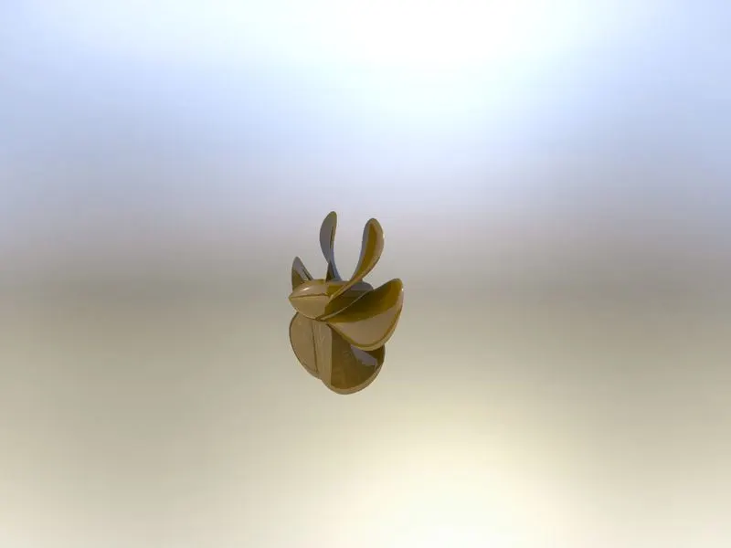
COMMANDS USED IN PROPELLER
IN 2D SKETCH
- Spline
- circle
- line
IN FEATURES
- revolve
- loft
- cut extrude
- fillet
- circular pattern
2.RADAR
A mandatory aid to navigation, the radar is used in identifying, tracking (with integrated ARPA) and positioning of vessels (including one’s own vessel) among other things in order to adhere to the COLREGs.
The marine radar is classified under the x-band (10 GHz) or S-band (3GHz) frequencies. The x-band, being of higher frequency is used for a sharper image and better resolution whereas the S-band is used especially when in rain or fog as well as for identification and tracking.
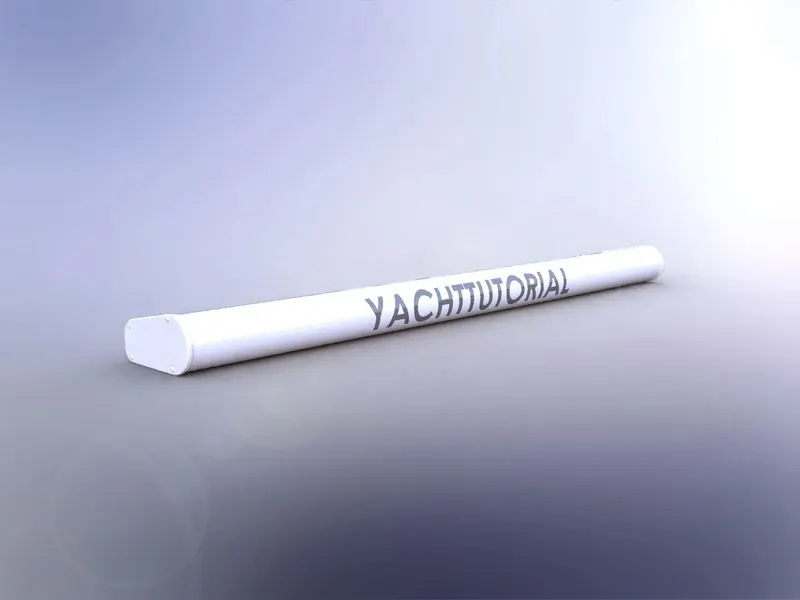
COMMANDS USED IN RADAR
IN 2D SKETCH
- Line
- circle
- line
- point
IN FEATURES
- boss extrude
- mirror
- cut extrude
- fillet
- circular pattern
- split line
3.HULL
A hull is the waterlight body of a ship, boat, or flying boat. The hull may open at the top (such as a dinghy), or it may be fully or partially covered with a deck. Atop the deck may be a deckhouse and other superstructure, such as a funnel, derrick, or mast. The line where the hull meets the water surface is called the waterline.There is a wide variety of hull types that are chosen for suitability for different usages, the hull shape being dependent upon the needs of the design. Shapes range from a nearly perfect box in the case of scow barges to a needle-sharp surface of revolution in the case of a racing multihull sailboat. The shape is chosen to strike a balance between cost, hydrostatic considerations (accommodation, load carrying, and stability), hydrodynamics (speed, power requirements, and motion and behavior in a seaway) and special considerations for the ship's role, such as the rounded bow of an icebreaker or the flat bottom of a landing craft.
RENDERING IMAGE
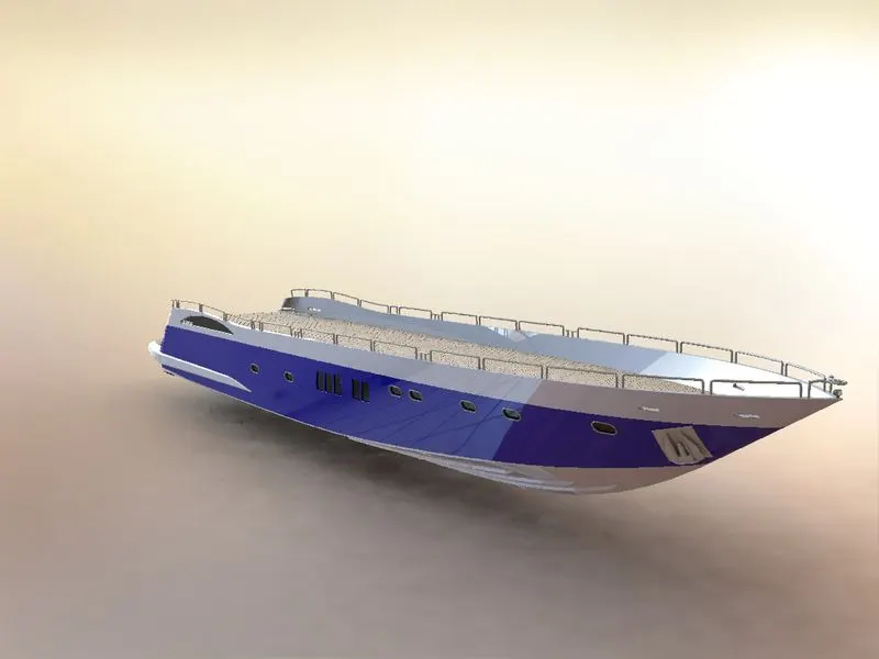
COMMANDS USED IN HULL
IN 2D SKETCH
- Line
- spline
- circle
- rectangle
- arc
- slot
- 3d sketch
- sketch picture
IN FEATURES
- surface loft
- surface trim
- surface extrude
- surface knit
- surface fill
- shell
- boss extrude
- cut extrude
- fillet
- chamfer
- sweep
- dome
- linear pattern
- revolve
- extrued thin
- split
- mirror
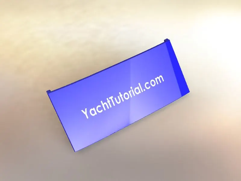
4.GARGE DOOR
A garage door is a large door on a garage that opens either manually or by an electric motor (a garage door opener). Garage doors are frequently large enough to accommodate automobiles and other vehicles. Small garage doors may be made in a single panel that tilts up and back across the garage ceiling. Larger doors are usually made in several jointed panels that roll up on tracks across the garage ceiling, or into a roll above the doorway. The operating mechanism is spring-loaded or counterbalanced to offset the weight of the door and reduce the human or motor effort required to operate the door. Less commonly, some garage doors slide or swing horizontally. Doors are made of wood, metal, or fiberglass, and may be insulated to prevent heat loss. warehouses, bus garages and locomotive shed have larger versions.
RENDERING IMAGES
COMMANDS USED IN GARAGE DOOR
IN 2D SKETCH
- Line
- spline
- circle
- text
IN FEATURES
- Cut extrude
- fillet
- mirror
- reference plane
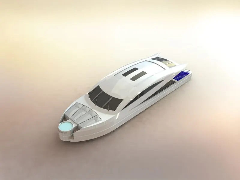
5.SUPERSTRUCTURE
A superstructure is an upward extension of an existing structure above a baseline. This term is applied to various kinds of physical structures such as bulidings, bridgs, or ship.The size of a watercraft's superstructure can have many implications in the performance of ships and boats, since these structures can alter their structural rigidity, their displacements, and/or stability. These can be detrimental to any vessel's performance if they are taken into consideration incorrectly.
RENDERING IMAGES
COMMANDS USED IN SUPERSTRUCTURE
IN 2D SKETCH
- sketch picture
- line
- 3d sketch
- spline
- circle
- rectangle
- center point arc
IN FEATURES
- surface extrude
- surface sweep
- knit surface
- fillet
- surface loft
- surface trim
- ruled surface
- surface extrude
- surface extend
- boss extrude
- mirror
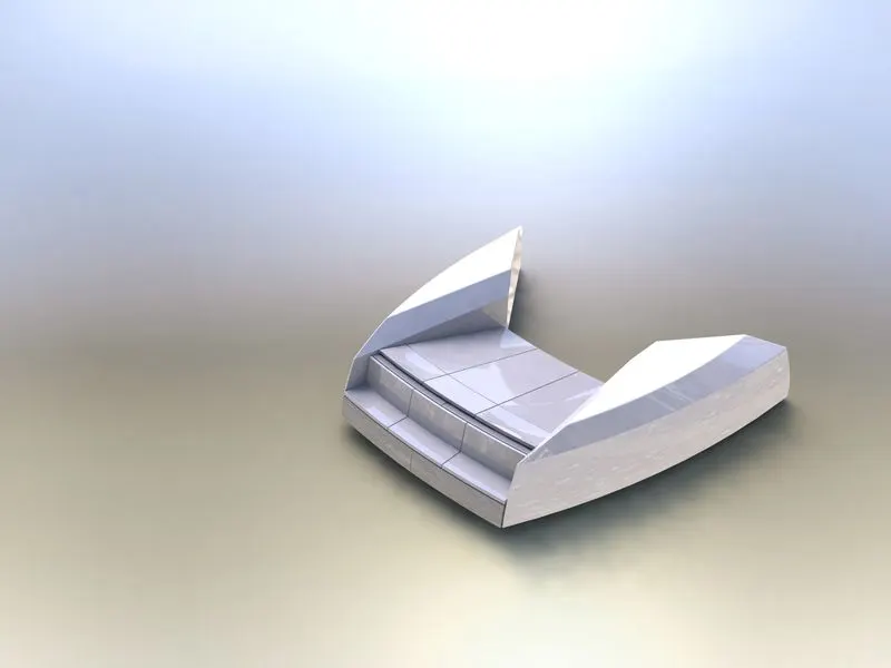
6.FRONT SEAT
hull. noun. the part of a ship or boat that floats on the water. The front part is called the bow and the back part is called the stern.
RENDERING IMAGES
COMMANDS USED IN FRONT SEAT
IN 2D SKETCH
- sketch picture
- line
- 3d sketch
- spline
- circle
IN FEATURES
- surface extrude
- surface sweep
- surface trim
- surface fill
- surface loft
- surface knit
- revolve
- chamfer
- cut extrude
- cut extrude thin
- fillet
- mirror
- dome
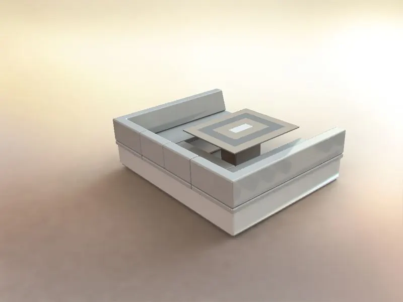
7.MIDDLE SEAT
The seat placed behind the superstructure it is just used for dinning and meeting purpose.
RENDERING IMAGES
COMMANDS USED IN MIDDLE SEAT
IN 2D SKETCH
- sketch picture
- line
- rectangle
IN FEATURES
- Boss extrude
- chamfer
- fillet
- mirror
- cut extrude
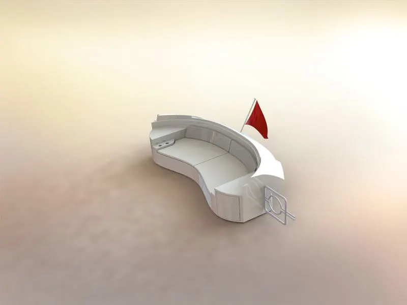
8.REAR SEAT
rear seat placed back side on the deck surface. it mostly used for rest place and also seeing the sea for nice view.the flag is placed on the rear seat.
RENDERING IMAGES
COMMANDS USED IN REAR SEAT
IN SKETCH
- Sketch picture
- line
- spline
- circle
- arcs
- rectangle
- 3d sketch
IN FEATURES
- surface sweep
- surface offset
- surface trim
- ruled surface
- surface knit
- surafce extend
- surface loft
- boss extrude
- cut extrude
- chamfer
- fillet
- sweep
- mirror
- revolve
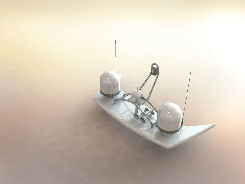
9.RADAR MAST
They are electronic navigation instruments that use a rotating antenna to sweep a narrow beam of microwaves around the water surface surrounding the ship to the horizon, detecting targets by microwaves reflected from them, generating a picture of the ship's surroundings on a display screen.
RENDERING IMAGES
COMMANDS IN RADAR MAST
IN 2D SKETCH
- sketch picture
- line
- spline
- rectangle
- arcs
IN FEARTURES
- boss extrude
- fillet
- sweep
- mirror
- chamfer
- fillet
- mirror
- revolve
- dome
- shell
ASSEMBLY
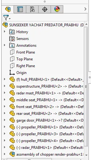
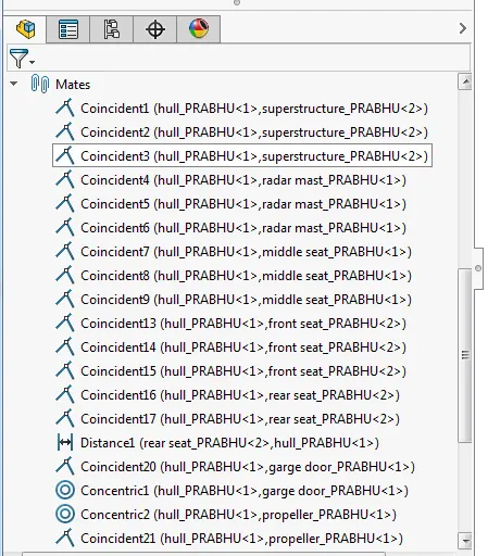
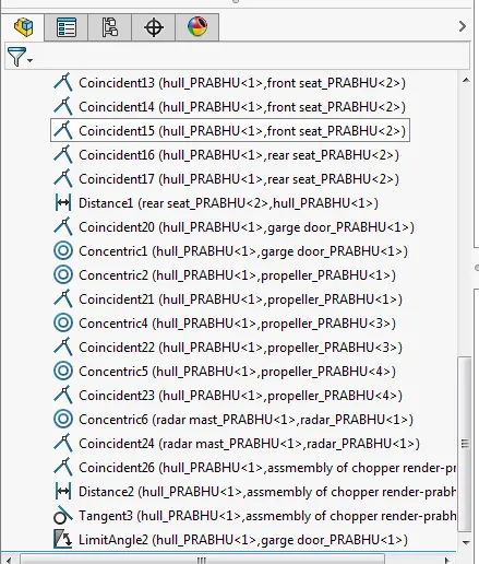
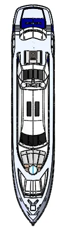
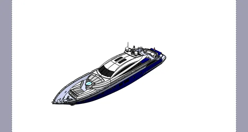
all the existing parts modelled the parts are assembled by using mate commands.
You can build complex assemblies consisting of many components, which can be parts or other assemblies, called subassemblies. For most operations, the behavior of components is the same for both types. Adding a component to an assembly creates a link between the assembly and the component. When SOLIDWORKS opens the assembly, it finds the component file to show it in the assembly. Changes in the component are automatically reflected in the assembly.
RENDERING IMAGES
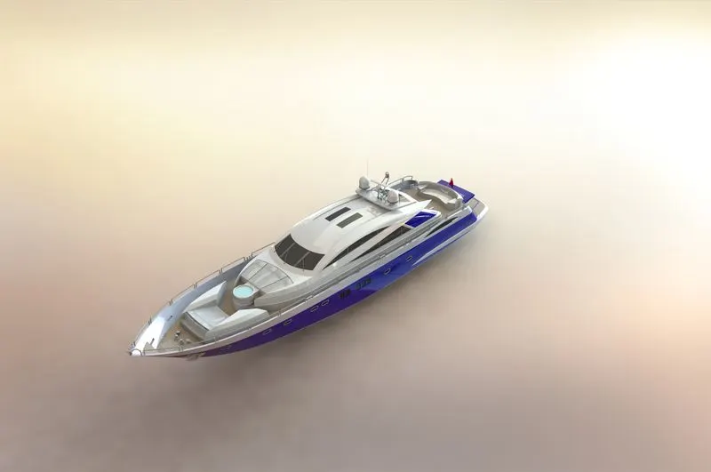
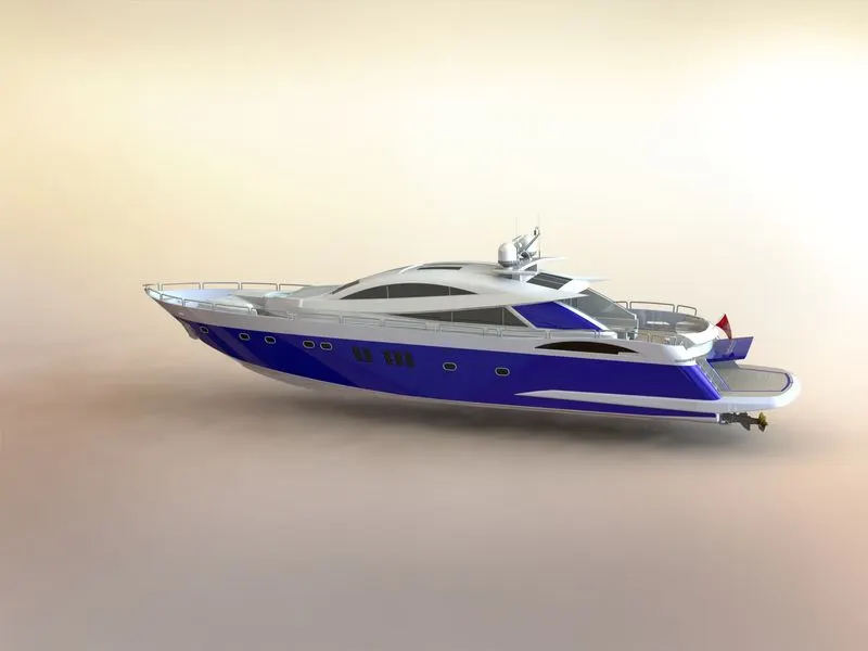
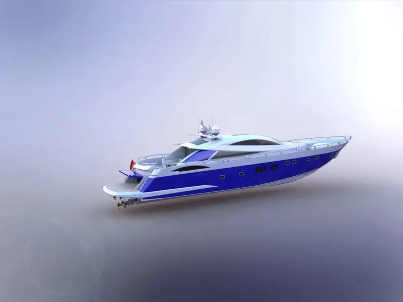
PHOTO VIEW 360
PhotoView 360 is a SOLIDWORKS add-in that produces photo-realistic renderings of SOLIDWORKS models. The rendered image incorporates the appearances, lighting, scene, and decals included with the model. PhotoView 360 is available with SOLIDWORKS Professional or SOLIDWORKS Premium.
CONCLUSION
Sunseeker yachat modell created and assembled successfully by using solidworks 2016 rendering the images by using photoview 360 degree.