Week 8 - Challenge 1 - Base Bracket Design
Base Bracket Design
Class A Surface Draft analysis
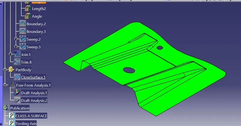
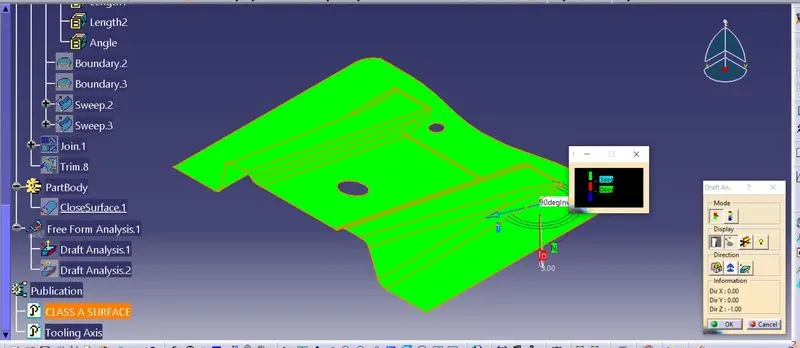
Plastic part draft analysis.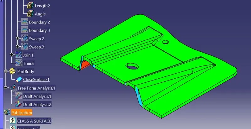
Tree Structure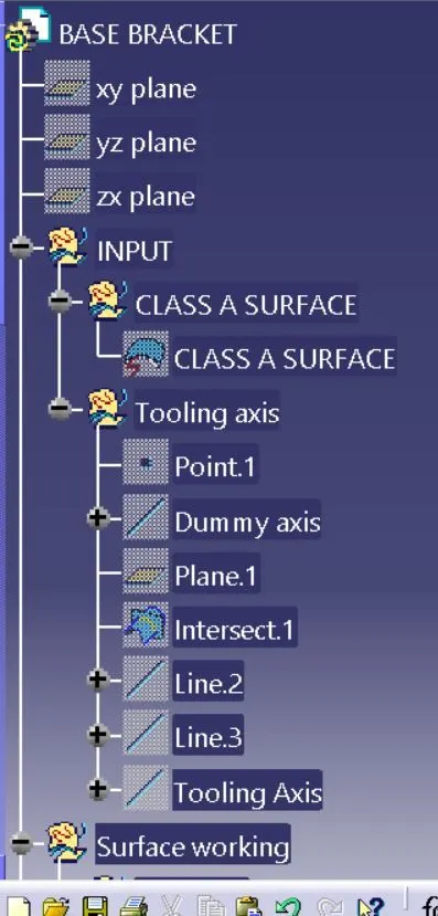
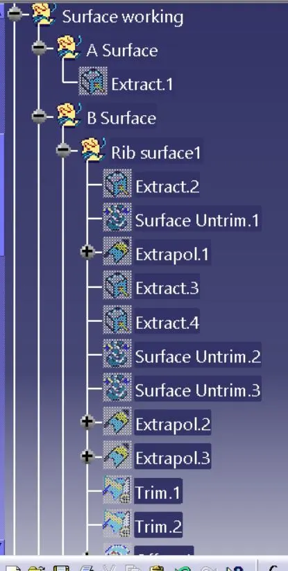
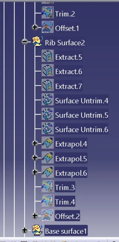
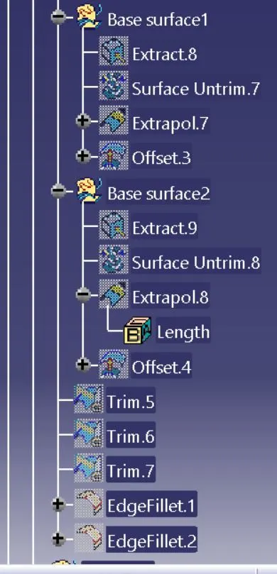
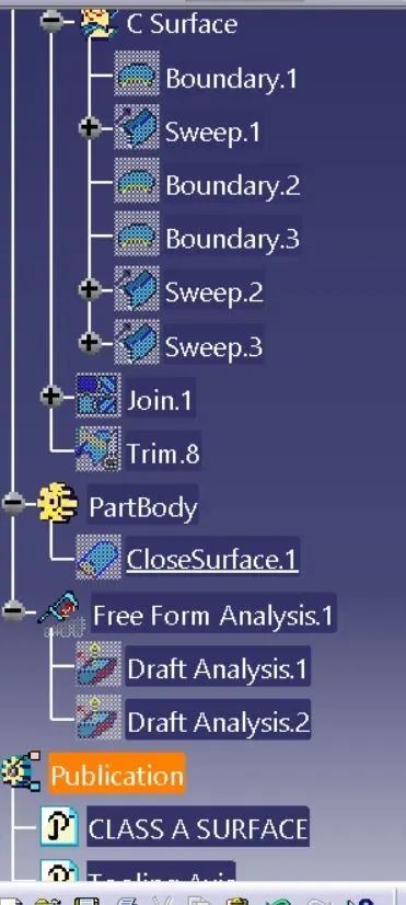
Surfaces Image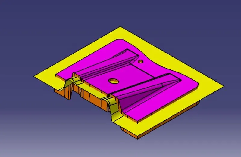
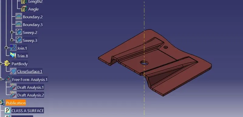
Publications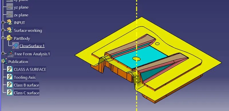
Isometric View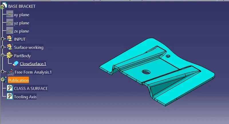
Front View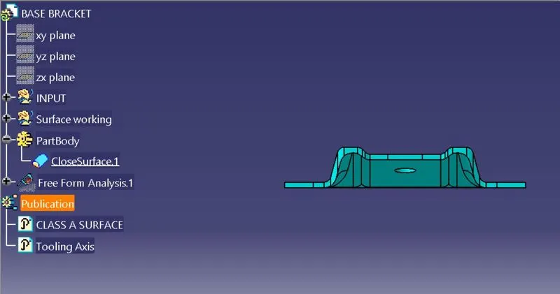
Top View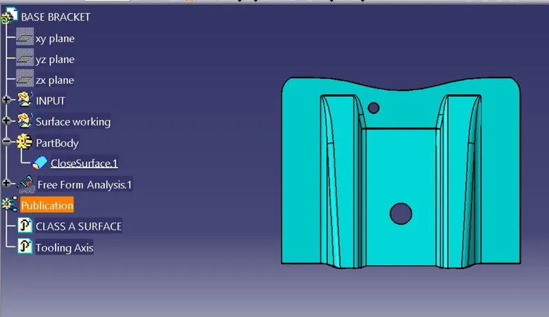
Side View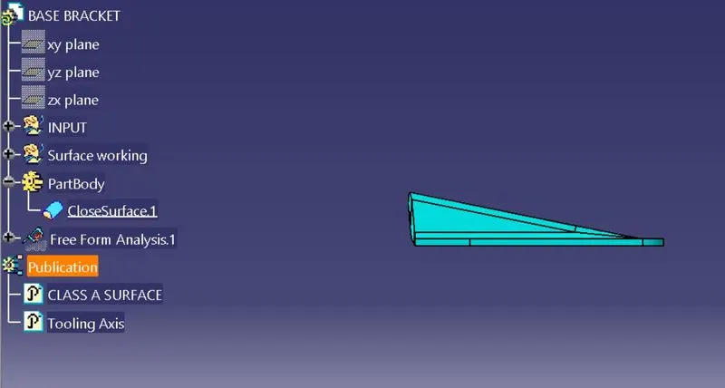
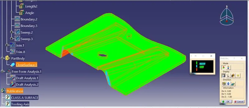
Draft Analysis.
No parts can be ejected from the tool if it is having a straight 90 degree profile from its base surface. A small draft angle is provided to each and every area of the component in order to get an easy removal of the component from the tool. Draft analysis technique is used to analyze whether our part model created in cad is manufacturable based on the draft condition applied. Here the part should get easily removed from the panel dies (in case of Sheet metal part) or Mold (in case of plastic). Here we are providing a direction in which components should eject inorder to get an easy removal of components from the tool. In other words it also lets us know whether the model is having a draft angle and how much is the draft angle from the tool direction.
The ideal draft angle for the plastic components is 3 degrees. This may vary according to the functional requirement. Apart from the draft angle consideration, remaining procedures for the draft analysis are similar to the above mentioned steps. The draft angle provided for the plastic features is 0.5 degree. This may also get varied accordingly.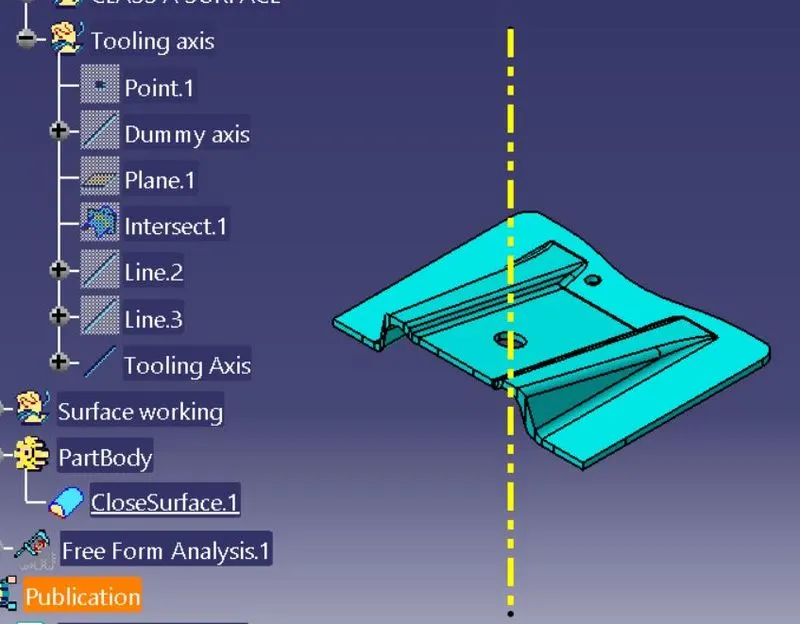
Tooling Direction
Tooling direction is the main consideration for plastic part and mould parts because it defines the movement of the mould part and the possibility of the plastic part coming out from the mould part (Core and Cavity).In Molding, machine arrangement is given to open the mould along a direction which is known as Tooling Direction.In other words. The mould is built from two separate halves (Core and Cavity) and tooling direction basically defines the direction of mould pulls apart.Tooling direction is known as primary direction.
PROCEDURE FOR CREATING TOOLING AXIS
- First, the given styling surface was imported into CATIA and checked for irregularities by using Join, Boundary and Disassemble option.
- By using the boundary option the boundary of the hole was created and the centre point was marked.
- Then a dummy tooling axis was created with the centre point in the z-direction.
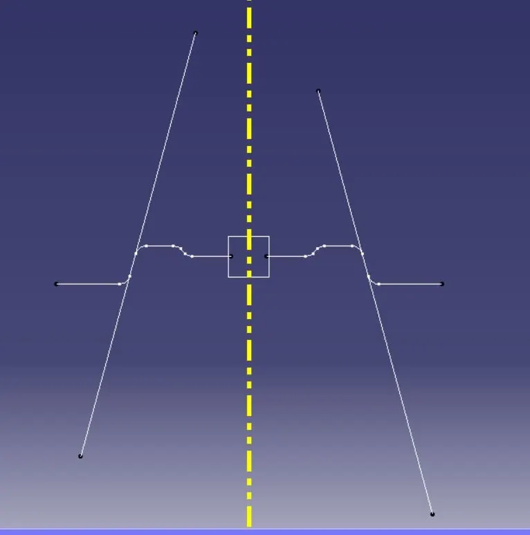
- By using the axis system the intersection curves were created over the yz plane and then the sides were extended by using point to point line then by using bisecting lines the tooling axis in Y direction was created.
- Bisecting lines were used to get the exact medium from the two sides so that maximum positive draft angle can be achieved.