Advanced Sheet Metal Design Using NX Cad Challenge_2_Box Assembly
NX_Box Assembly_Harish Patil.
Design of Box Assembly using NX sheet metal application.
Objective:
To design a Box assembly by using Siemens NX sheetmetal Application.
Introduction:
NX Siemens contains a series of applications that support different workflows, such as creating parts, building an assembly, or producing a drawing. And NX Siemens sheetmetal application provides an environment for the design of sheetmetal parts used in Machinery, Automotive industry and Aerospace etc.
Design Of Methodology:
Work flow to design a Box Assembly.
- Sketch the 2D shape of the Box Assembly.
- Construct the Base feature using tab.
- Add Flange ,Closed Corner & Hem Flange.
- Mirror body & add Unite.
- Unbend the part and add other features such as dimple, hole and beads.
- Rebend the part after applying of required features
- Create flat pattern.
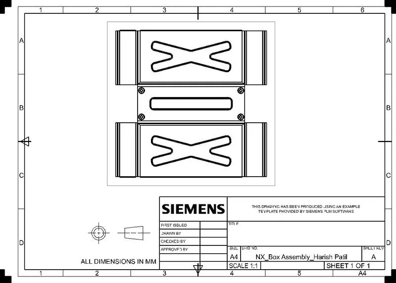
- Create a drawing sheet by using of drafting.
Description:
Tools used:
- Sketch: Used to create a 2D sketch on the plane.
- Line: Used to draw a line.
- Rectangle: Used to draw a rectangle.
- Fillet: Bend the sharp edges.
- Circle: Used to draw a circle.
- Point: Used to create a point in the sketch.
Features Used:
- Tab: Use to create a base feature by extruding a sketch along a vector by thickness valve or by adding material to existing faces & bend regions of sheet metal part.
- Normal Cutout: It is used to create the cutout to the material by projecting a sketch onto the model and then cutting perpendicular to the faces intersected by the projection.
- Bend: It is used to bend the material by projecting a sketch on the model perpendicular to the faces intersected by the projection.
- Flange: Use to add a flat flange at an angle to a planner face & add a bend b/w the two.
- Closed Corner: Use to modify two flanges in one operation & to close the corner where the two flanges meet.
- Hem Flange: use to modify an edge of a sheet metal part by folding it onto itself for the purpose of safe handling or to increase edge stiffness.
- Mirror: Use to mirror a feature or entirie body with the reference of plane.
- Untie:Joining two bodies.
- Break Corner: Use to round or chamfer sharp corners of a tab or flange.
- Unbend: It is reverse of bend feature , used to add some more feature.
- Hole: Use to create a hole in the body using standard valves.
- Dimple: Use to lift an area of the model inside a sketch that simulates a stamping tool.
- Bead: use to lift the material along the contour of a sketch that simulates a stamping tool.
- Rebend: Use to gain the original position.
- Flat Pattern: Used to create a flat pattern feature form the formed sheetmetal part.
- Base View: Creates the model based view on the drawing sheet.
Images: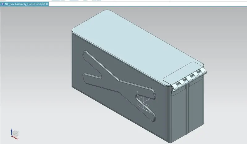
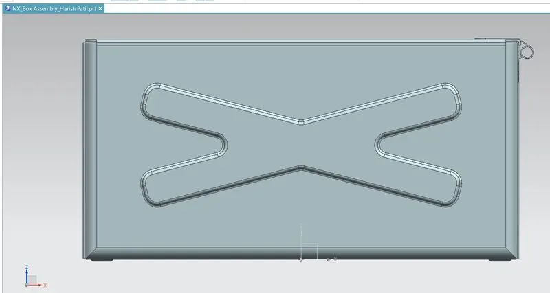
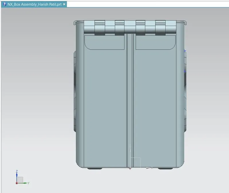
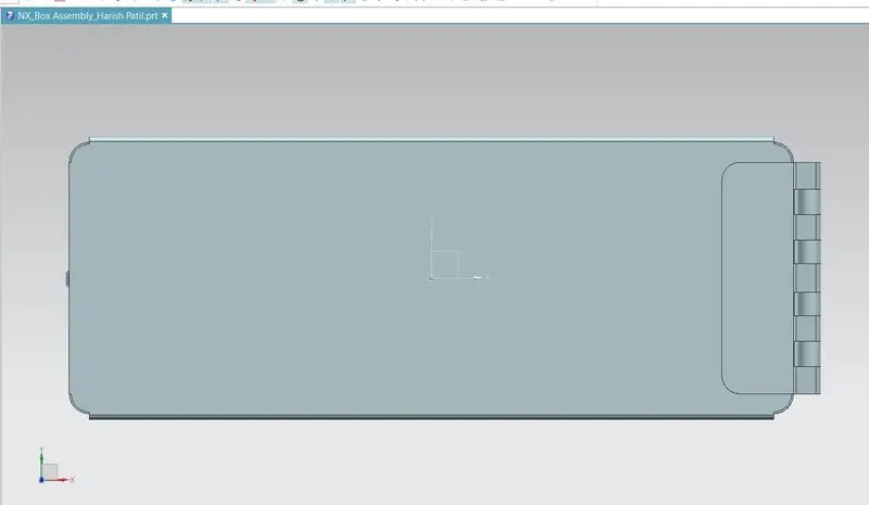
Conclusion :
Design Box Assembly using sheet metal in NX & view the drawing using drafting application.