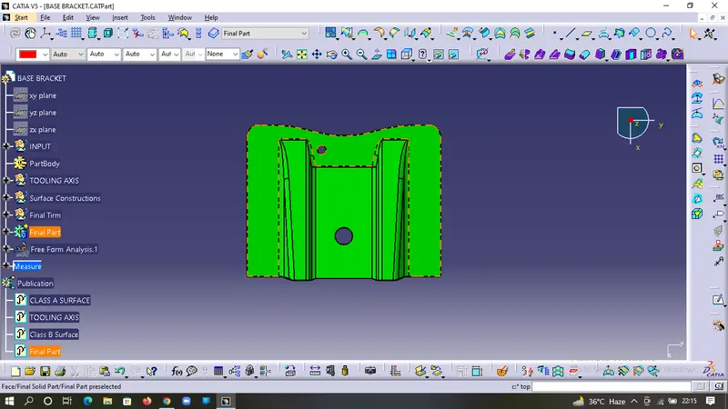
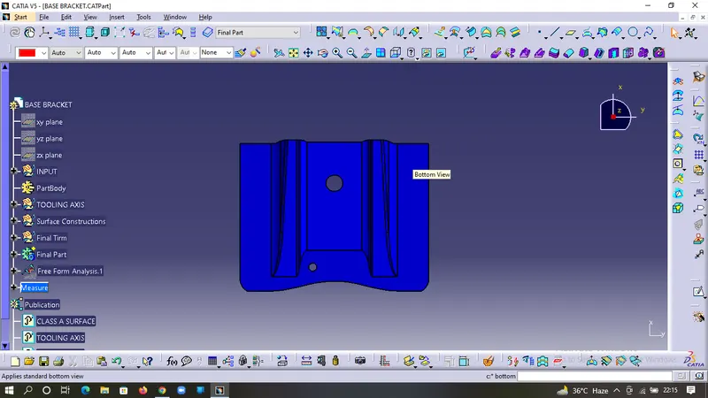
Week 8 - Challenge 1 - Base Bracket Design
Report
In order to create a tooling axis we need to first look for any hole or pocket or flat surface which have the most complexity.
Then make a Dummy Tooling Axis for our own referance, and then look for any surface that seems Parallel to it.
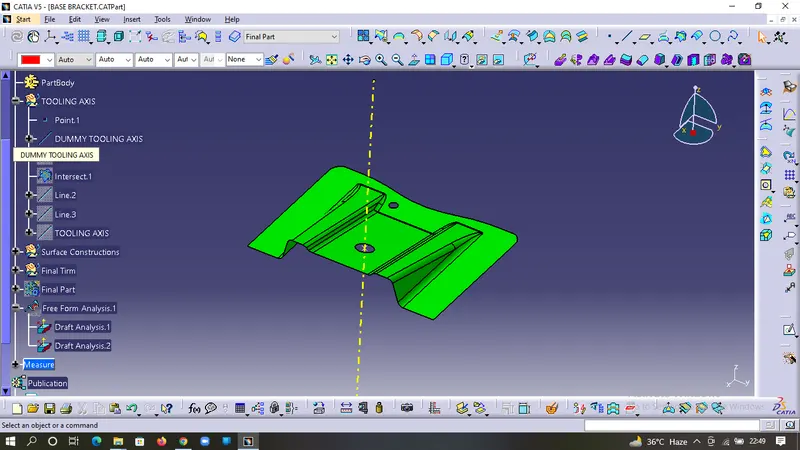
Then take the referance of the A Class Surface and draw the lines for the surface that looks parallel to the dummy tooling axis.
Then take the bisecting line of all the line that were created (that were almost parallel to the dummy tooling axis).
The line which we get now is our Final Tooling Axis.
Change the format of the line and make the publication for the same.
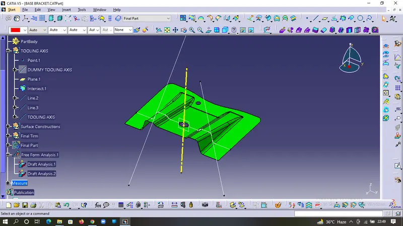
Now after creating the tooling axis we need to validate that the tooling axis that we have made is correct, for that we have the Draft analysis option,
In Draft analysis we check that all the faces must have atleast 3 degree of draft (as per Standards)
For Draft analysis we need to change to material mode and then start the draft analysis.
First move the axis flag on the top of the tooling axis and lock it.
Then pick the part body and select & customise the color scale, if any surface shows abnormalality then correct the tooling axis otherwise finalize the tooling axis.
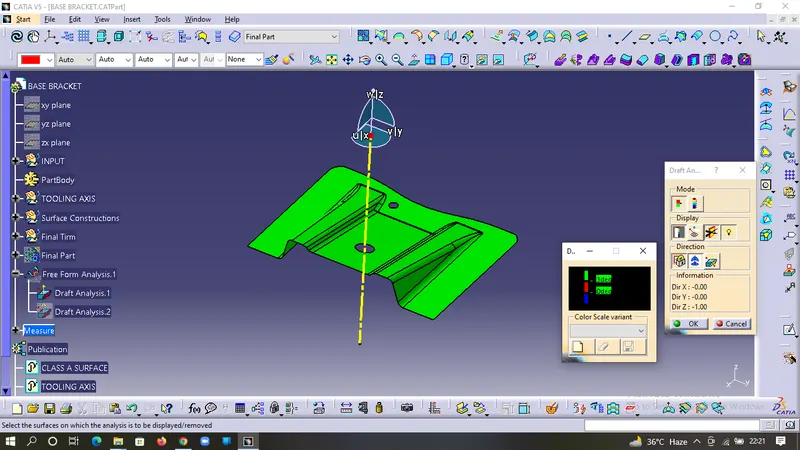
Drawing 1
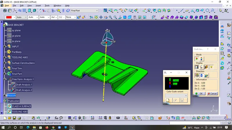
Screenshots of the Draft analysis report for both the given Class-A surface and the final plastic component
Class A
Final Plastic Conponent
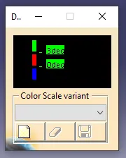
Images of the color scale variant
Colour Varient Scale For Class A
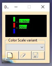
Colour Varient Scale For Final Part
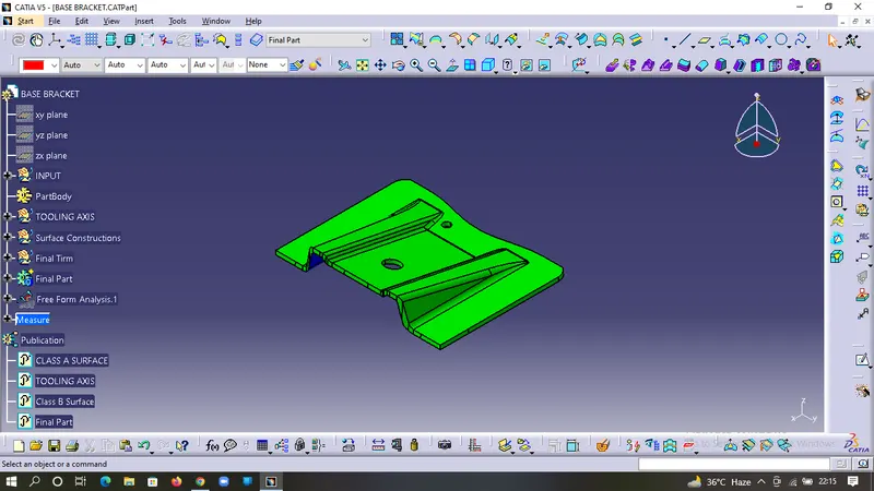
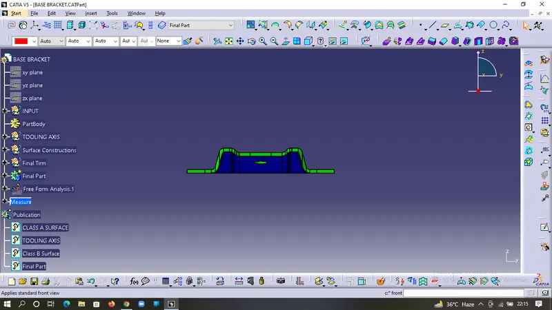
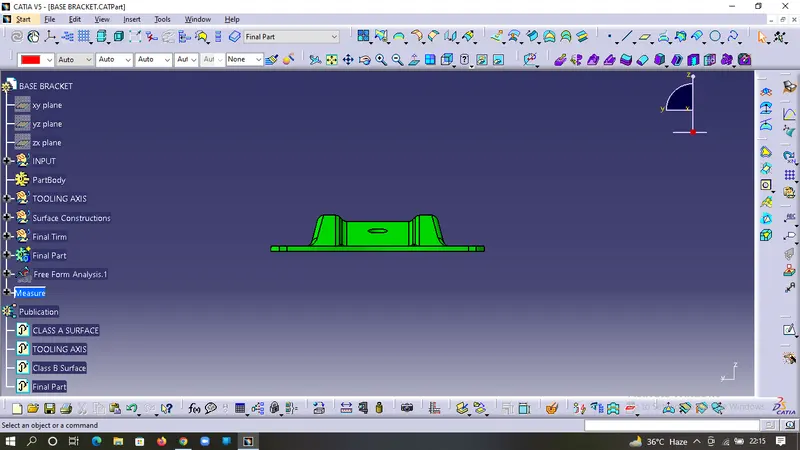
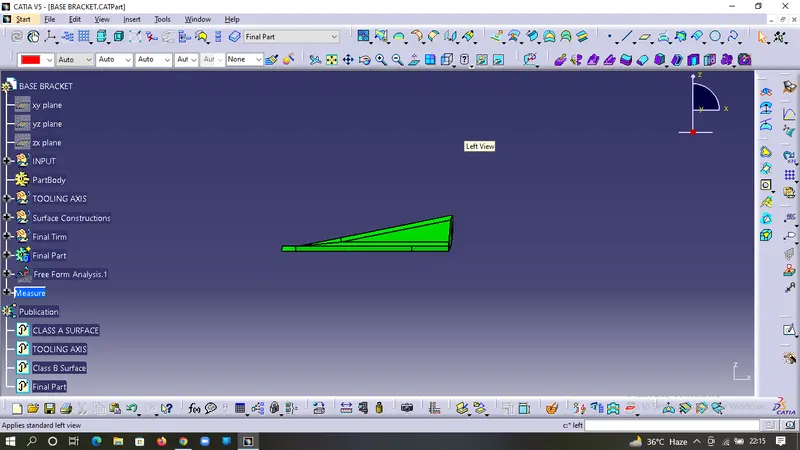
Screenshots of the solid model with the proper color code of the draft angle in various orientations (Isometric, Front, Side, and Top View)