Week 8 - Challenge 1 - Base Bracket Design
ABSTRACT
A Bracket is a component used to support load or any attachments to structural element for heavy vehicle. In an automotive vehicle, the engine rests on brackets which are connected to the main-frame or the skeleton of the car. Hence, during its operation, the undesired vibrations generated by the engine and road roughness can get directly transmitted to the frame through the brackets. This report demonstrates the design of a Plastic Component - Bracket using industry principles such as Draft angles, Draft Analysis, Determining and implementing of Tooling Axis,
Class A, Class B and Class C surfaces. The component is designed using CAD package CATIA V5.
OBJECTIVE
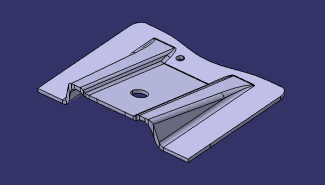
The main aim of this challenge is to create the Base Bracket Plastic component through the given Class-A surface. To begin with, the tooling axis for the given Class-A Surface and to create B-Surface, C-Surface from Class-A surface and perform draft analysis for both Class-A surface and the plastic component created. Taking the Thickness of the component to be 2.5 mm.
Introduction
• Draft is an angular tapering given at the design stage to every Plastic Component that has to be manufactured.
• It is given in the direction of the Mold Movement. The Draft allows the parts to release easily from the mold without creating friction between the surface of component and the core and cavity plates.
• When a Plastic component cools down inside the mold, the natural tendency of it is to shrink and attach to the core or cavity half. The movement of mold opening causes friction on the walls of the component as well as the core/cavity blocks.
• This reduces the life of the mold as well as the component itself. The component may also have rough surface finish as well as weak structure due to this.
• This problem can be solved by giving draft to the component. Most applications require minimum draft angles of around 0.5o to 1o , however 3o
draft angles are widely accepted for cost saving purpose.
• 7 deg. Draft angles are given to textured surfaces like Instrument Panels. Minimum possible draft angles are given to screw bosses, ribs and stiffeners due to their critical nature.
Following tools were used
1. Extract
2. Un-trim
3. Trim
4. Extrapolate
5. Offset
6. Edge fillet
7. Boundary
8. Sweep
9. Join
10. Close (part design)
Tooling Axis:
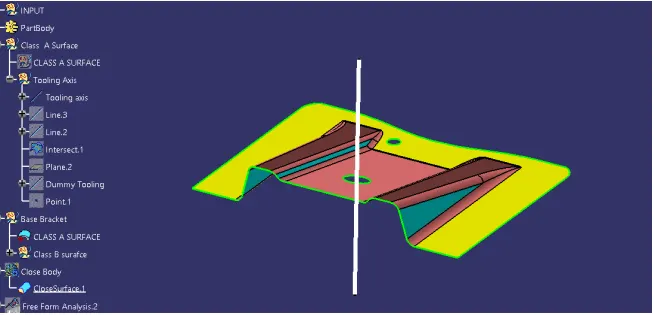
Tooling Axis is the direction in which the Mold opens and closes. Part Drafts are given balong this axis.
Procedure
1. First ensure the class-A surface is properly joined and has no discontinuity on it. For this we can use boundary command or join command.
2. Analyze the model manually or visually to see which direction is most suitable for tooling axis.
3. As in 3D view we can see 2 holes and a flat surface, we can directly take the tooling axis perpendicular to that. But to be sure,let us analaze from all the views. The below images of the front side and top views shows the areas that we have to keep in mind while choosing tooling axis. As from X we cannot see one hole so we cannot take axis along this. In Y we cannot see any holes so here too we cannot take tooling
axis. But in Z we can see 2 holes and flat surface so we can take tooling axis.
4. Intersect the ZX plane of the axis system with the input and we can see that there is no surface that can create problem during.
5. Intersect ZY plane and we are unsure of these two surfaces, so we make a line and bisect them both and this will be our tooling axis which, not so surprisingly, is the same as our guessed tooling axis.
Draft Analysis
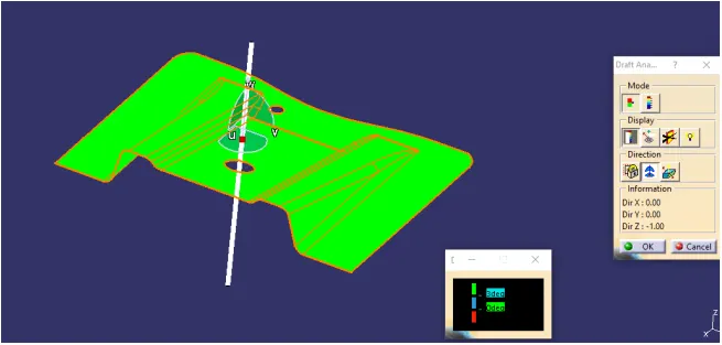
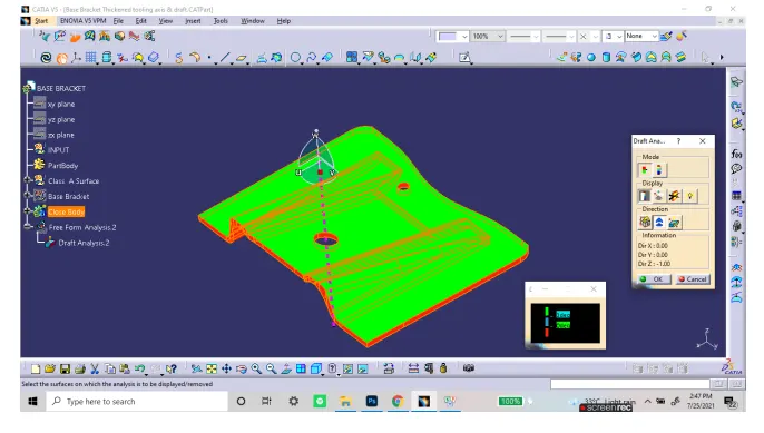
Draft Analysis is a tool in CATIA which identifies the zones which deviates from the specified values of angles along a defined draft direction using colour codes. It highlights the regions of draft using colours. Draft analysis is the first step performed after receiving the Class A of the component.
Class- A Surface
In automotive design, a class A surface is any of a set of free form surfaces of high efficiency and quality. It is the visible aesthetic surface of any automotive component. Class A surface refers to those surfaces which are visible and abide to the physical meaning, in a product. This classification is primarily used in the automotive and increasingly in consumer goods industry. It is a requirement where aesthetics has a
significant contribution. For this reason, the exterior of automobiles is deemed Class-A.
Class- B Surface
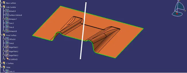
Class B surfaces are Engineering Surfaces which are invisible to the eyes or often on the back side of the Class A surfaces. It is mainly the thickness of the component or Class A. These surfaces need to be designed as per the Class A surface i.e., the continuity, thickness of the component, functionality etc should be maintained. These surfaces include the main engineering features such as Screw bosses, Ribs, Snaps, Stiffeners and fixations. B surfaces also do not contain any aesthetic styling content and textures since it is not visible to eyes.
• Extract the relevant surfaces from Class-A surface which excludes the Fillets and holes.
• Use Untrim Command to untrim the surfaces and create a natural extend.
• Extrapolate the untrimmed surfaces so that each of them intersects clearly and pass way forward than the Class A which will help in its trimming in further operations.
• Trim the extra surfaces to obtain similar extended surfaces as in Class A.
• Offset the obtained Trim to the value of required Thickness of the Part. In this case of Bracket, the thickness value is 2.5 mm. The offset faces are the part of B-Surface.
• Do The Similar operations namely : Extract, Untrim, Extrapolate, Trim, Offset for the other faces from the Class A excluding the Fillets.
• Trim the extra surfaces such that it crates similar surface as Class A.
• Create Fillets while maintaining the part thickness between the Class A and Class b surfaces. The Value of Fillet is given by the equation (B surface fillet = A surface fillet + - Thickness of the Part). The sign + or – must be decided so as to maintain the part thickness which in this case is 2.5mm.
• The fillet values can also be obtained by maintaining the thickness in the intersection sketch of the two surfaces.
Class-C surface
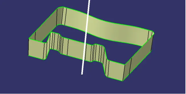
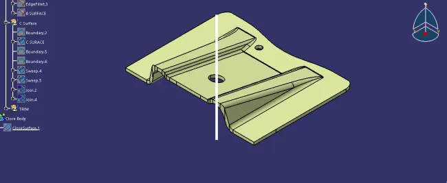
Class C surfaces are connectors between Class A and B surfaces. This surface connects both A and B surfaces along the Tooling Axis. It contains the draft as per the design. Its is basically the thickened surface between both A and B surface.
• Use Boundary option to extract the outer boundary of the Class A surface .
• Use Sweep Operation to extrude the boundary using the Draft direction option and selecting the Tooling Axis as the direction. Use draft angle as 3deg. and Sweep it well beyond the B surface .
• Use similar options of Boundary extract and Sweep for the holes on Class A .
• Join all the Swept surfaces along with the Class A Surface.
Conclusion
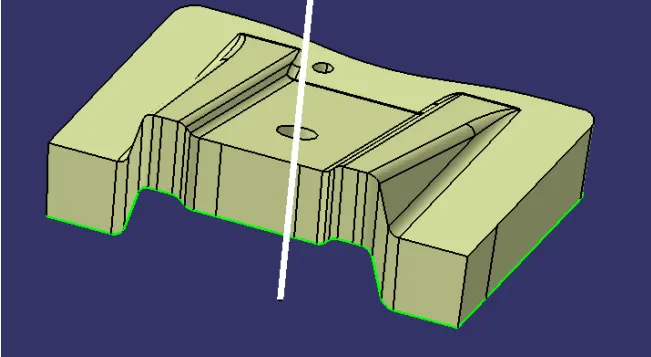
The Design of Plastic Component - Base Bracket from Class A is completed using concepts of Draft angle, Draft Analysis, Tooling Axis, Class B and Class C creation and converting Closed surface to a solid part