Radar Mast & Final Assembly of Yacht
Name_Radar_Mast
Name_Yatch_Assembly
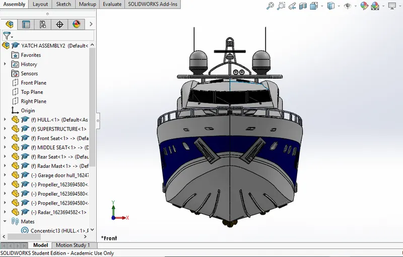
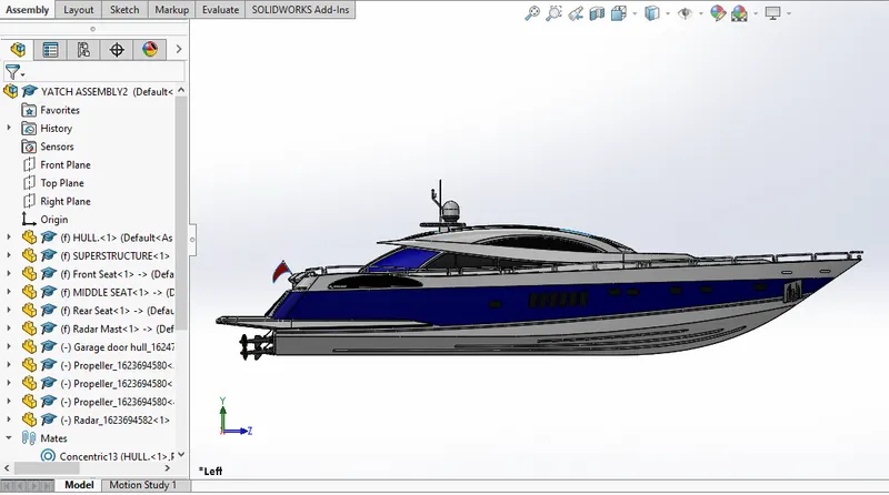
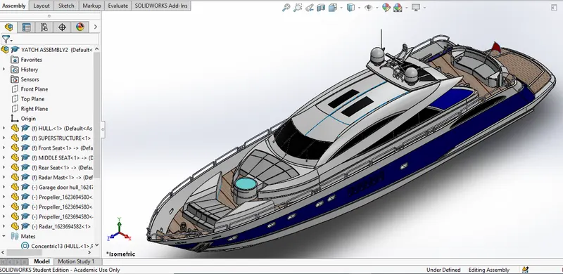
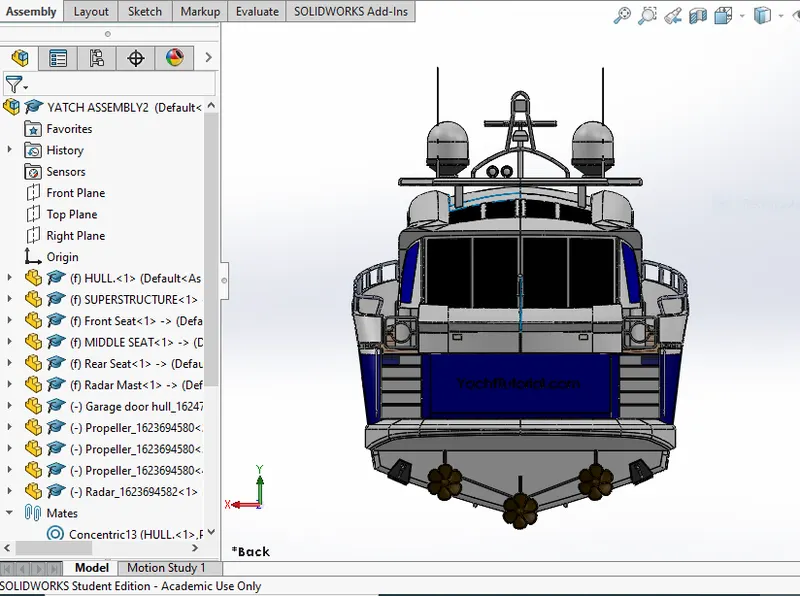
REPORT
MODELLING, ASSEMBLING & PHOTO REALISTIC RENDERING OF AN AMERICAN PREDATOR YATCH
OBJECTIVE:-
The main objective of this project are:
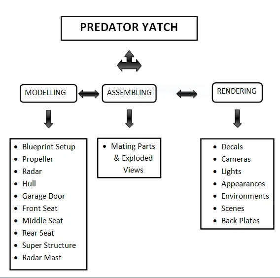
- To design and model all the parts of an American Predator Yacht and assembling it to create the Photo Realistic rendering of the yacht.
INTRODUCTION:-
-
Using SOLIDWORKS 2020 all the modelled parts were assembled by adding proper mates and constraints to create the Photo-Realistic rendered image of the Yacht.
- Photo view 360 is a SOLIDWORKS add-in that produces photo-realistic renderings of SOLIDWORKS models.The rendered image formed with the appearances, lighting, scene, and decals.
-
SOLIDWORKS Visualize allows you to leverage your 3D CAD data to create photo-quality content in the fastest and easiest way you can–from images to animations, interactive web content, and immersive Virtual Reality. Bring your products to life.
DESIGN APPROACH & METHODOLOGY:-
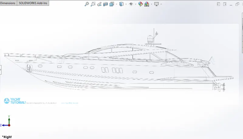
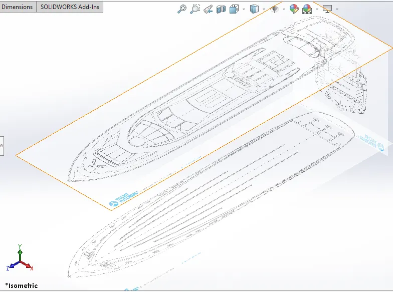
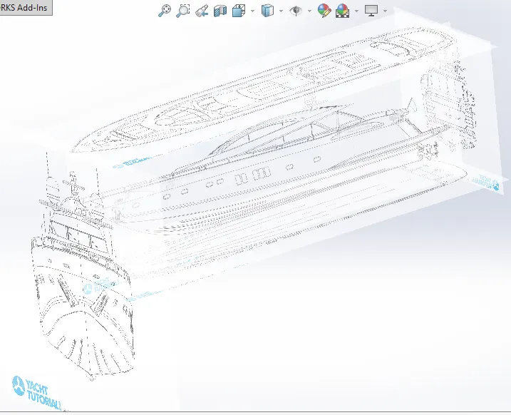
- BLUEPRINT SETUP:-
- PROPELLER:-
The main function of propeller is to propel the ship in the forward direction by producing thrust on water .
Its working principles are Newton's third law of motion & Bernoulli's theorem.
Features used to create Propeller:-
In Sketch
- Spline
- Circle
- Line
In Features
- Revolved Boss/Base
- Lofted Boss/Base
- Extruded Cut
- Reference Plane
- Circular Pattern
- Fillet
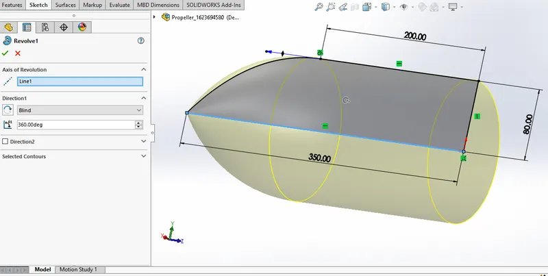
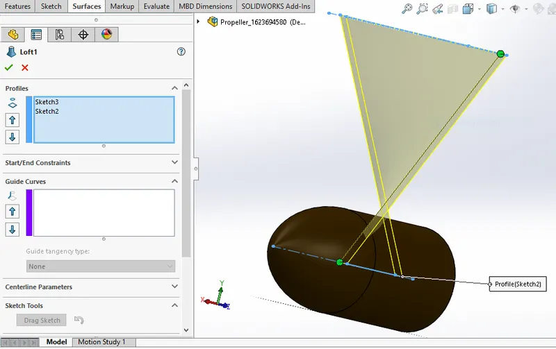
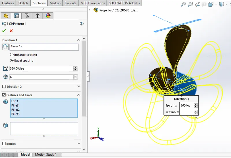
REVOLVED BOSE/BASE:-
Revolved Surfaces Revolves a sketch or selected sketch contours around an axis to create a surface features.
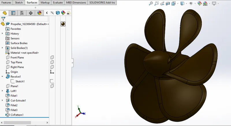
-
The center portion of the Propeller was sketched and revolved using Revolved Boss/Base.
-
Then the Blades were created using the Reference Plane, Lofted Boss/Base and Fillet.
-
Then the remaining five blades were created by using Circular Pattern.
-
Then the center circular portion was removed using Extruded Cut option.
-
Finally the part was saved by adding the appearance.
- RADAR:-
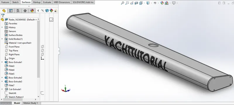
Features used to create Radar:-
In Sketch
- Line
- Circle
- Point
- Text
In Features
- Fillet
- Extruded Boss/Base
- Mirror
- Sketch Pattern
- Extruded Cut
- Split Line
EXTRUDE BOSS/BASE:-
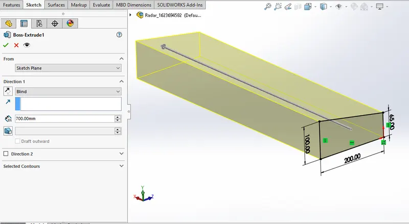
One of the oldest commands in the SOLIDWORKS software is the boss/base extrude command. An Extruded Boss/Base feature will allow you to take a 2D sketch and add thickness to it in the third dimension. Every few releases, this feature gets some terrific functionality added to it.
SPLIT LINE:-
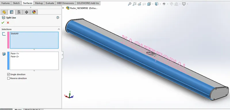
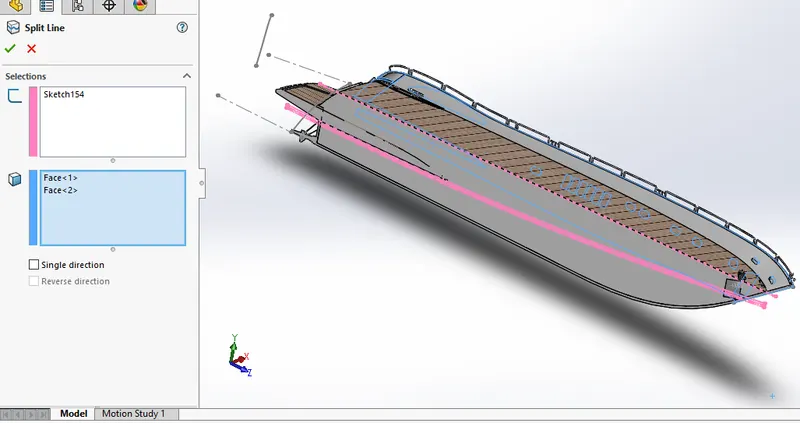
The SOLIDWORKS Split Line tool is used to project an entity (sketch, solid, surface, face, plane, or surface spline) onto other surfaces or curved/planar faces. You are also able to split faces on multiple bodies with one command.
PROCEDURE TO CREATE A MODEL OF RADAR:-
- By drawing the required sketch the body of the Radar was created using Extruded Boss/Base.
-
By using the Sketch Pattern the four Dotted holes were created using Extruded Boss/Base and ExtrudedCut.
-
The Radar has a circular slot underneath which was created using the Extruded Cut.
-
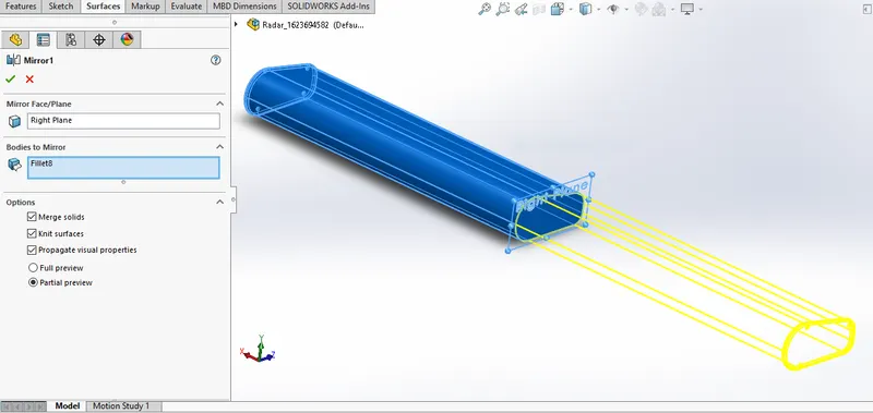
The other half was mirrored with the help of mirror tool.
-
The Text over the Radar was created using the Text option in sketch and then the Split Line was used togenerate over the face of the radar.
-
At last the radar must be filleted around the edges of the body and also around the four holes.
-
Finally the part was saved by adding appearances.
HULL:-
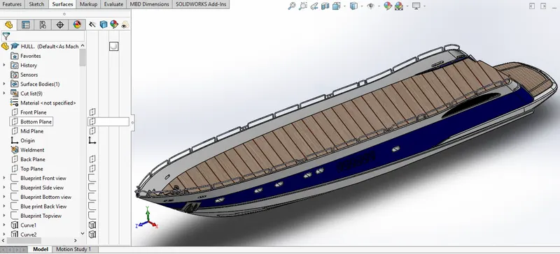
A hull is the watertight body of a ship, boat, or flying boat. The hull may open at the top, or it may be fully or partially covered with a deck. Atop the deck may be a deckhouse and other superstructures, such as a funnel, derrick, or mast. The line where the hull meets the water surface is called the waterline.
Features used to create Hull:-
In Surfaces
- Extruded Surface
- Revolved Surface
- Lofted Surface
- Surface Trim
- Surface Knit
- Delete Face
In Features
- Projected Curve
- Chamfer
- Fillets
- Split
- Mirror
- Extruded Cut
- Split Line
- Refrence Plane
- Extruded Boss/Base
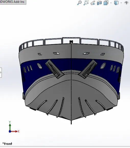
PROCEDURE TO CREATE A MODEL OF HULL:-
-
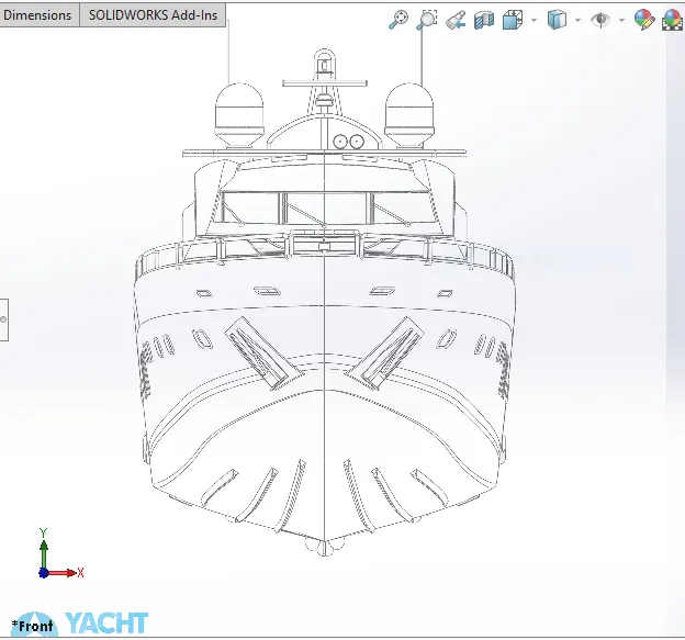
The first step for modeling the Yacht was creating a blueprint of it.Then the blue print was placed at therequired planes, by using it first the hull was designed.
-
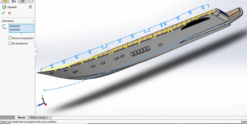
To get the shape of the hull the projected curve was produced by drawing the required sketch using splines with the help of blueprint.
-
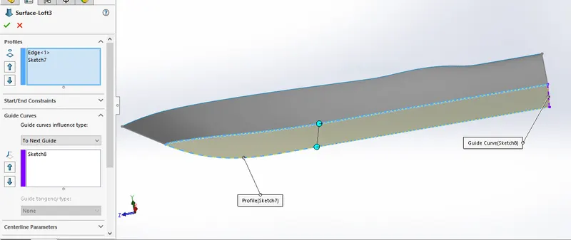
Then the curves were lofted to create a lofted surface and the remaining unwanted surface was trimmed using surface trim.
-
Then the back portion of the hull were the propeller needs to be placed was extruded using Extruded Surface and all the surface created must be Knitted together to remove the gaps between the surfaces.
-
Then the offset option was used and another surface was created and both surface was filled using surface fill to create the outer shell of the hull which will be converted into a solid body at last.
-
Shell feature was used to create the front portion of the hull where the deck surface meets. Then the deck surface was created using Extruded Boss/Base and Extruded Cut.
-
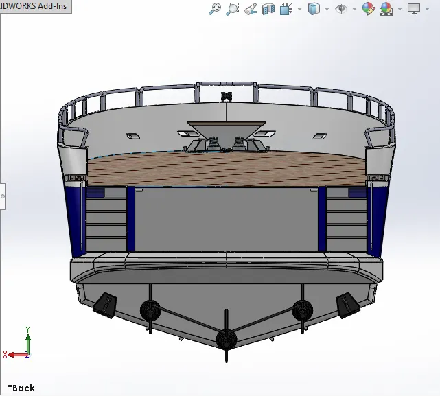
Then the required chamfers and fillets were created wherever necessary. All the windows and Portholes were created using Extruded Cut and Fillets were add around the edges.
-
For creating the smooth edges around the berth window the reference plane were created and a circle for required dimensions were make pierced and then swept around the edge of the windows.
-
The Rails at the bottom of the yacht were created using Extruded Boss/Base and the chamfers wereapplied both the sides.
-
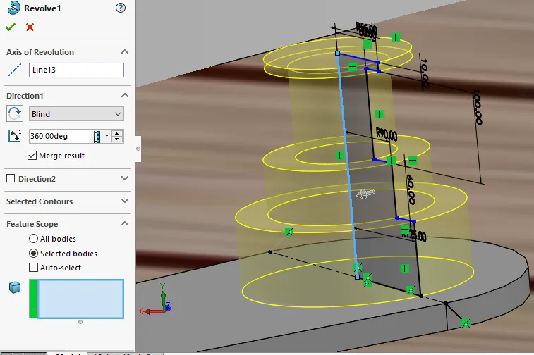
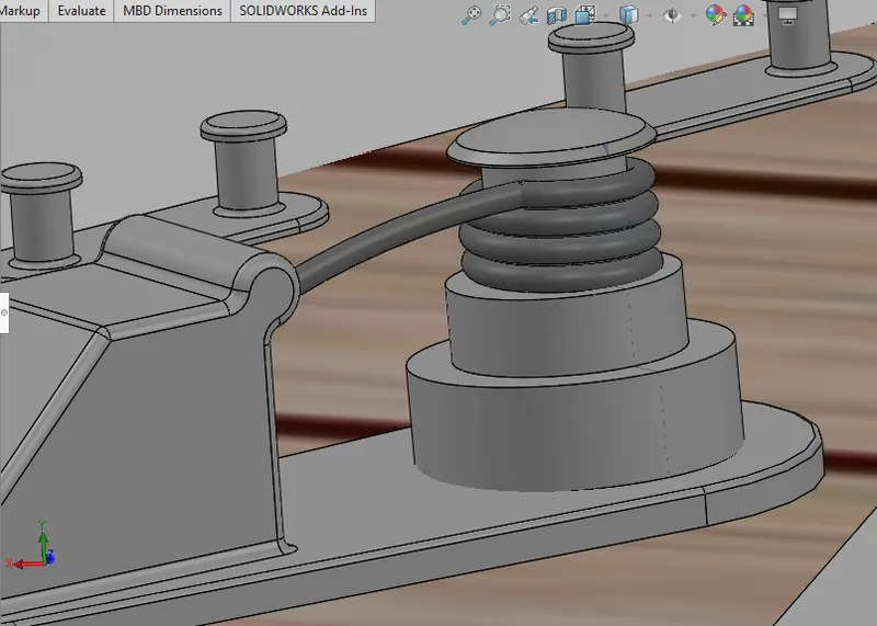
The Cable Rollers were created using Extruded Boss/Base and Swept Boss/Base and the head part of it was created using Revolved Boss/Base and Extruded Cut was used to cut through the extrude and a Dome was created over it.
-
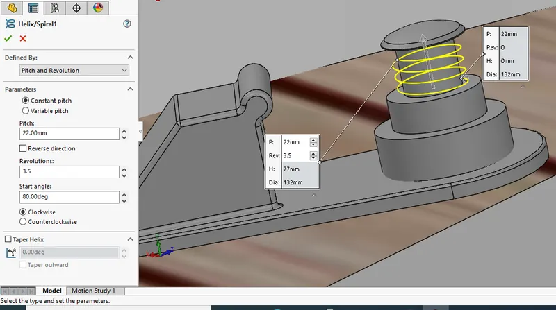
Helix/Spiral sketch was created to sweep the rope around the Cable Rollers. By using Slot option the Rope hangers were extruded and the dome was applied and then the Linear Pattern was used to create one more.
-
The window bars were created using Extruded Boss/Base & the staircase was created by using extruded boss/base and the hand support bar was created using Swept Boss/Base.
-
The Railings around the Hull was generated with the help of blueprint and the projected curve was produced and the railing reference was swept using Swept Boss/Base.
-
The Axles for the propeller and the surfer were created using Revolved Boss/Base option and using the 3d sketch.
-
The Anchors were created by sketching the first half and extruded using Extruded Boss/Base and theother half was mirrored.
-
Finally the Garage Portion was created by using Extruded Cut and the portion was saved for later use by using Split option. By using the Split line option the Painting portion for our hull was split separately.
-
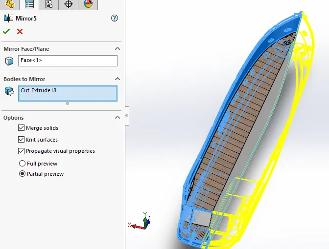
Then the other half of the Hull and the Axle of the surfer and propeller was mirrored to form the complete hull using Mirror tool.
-
Now the part was saved by adding proper appearances and fillets.
- GARAGE DOOR:-
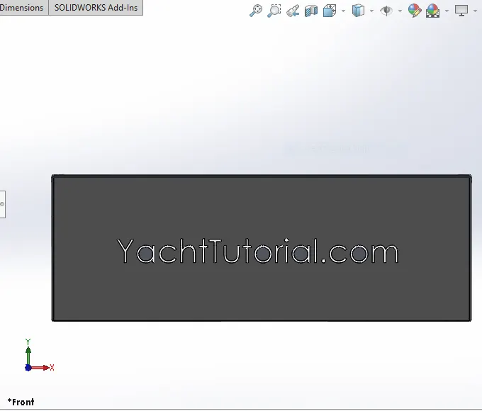
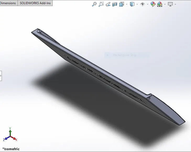
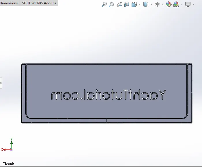
Opening up the side of the yacht offers a huge amount of additional possibilities to the yacht, such as tender storage, beach clubs and others. Cramm doors are highly reliable even under the toughest sea conditions. The design of the yacht door is based on a 3D model of the client’s yacht, and custom-made in aluminium, steel or stainless steel to enable differing shapes, sizes and weights.
Features used to create Garage Door:-
- Shell
- Fillet
- Text
- Spline
- Extruded Cut
- Mirror
- Reference Plane
PROCEDURE TO CREATE A MODEL OF GARAGE DOOR:-
- The solid body split while creating the Hull was imported to model the Garage Door.
-
Then by using the shell feature the solid body for our garage door was created and proper fillets wereapplied.
-
By using the Extruded Cut the Chamfered face for the door was created.
-
Then the door holders on both sides were created using Extruded Cut.
-
Then the second half of the Garage Door was created using Mirror tool after applying the required fillets.
-
Then the text over the garage door "YATCH TUTORIAL.COM" was created using the text option in sketch feature.
-
Finally the part was saved by applying proper appearance.
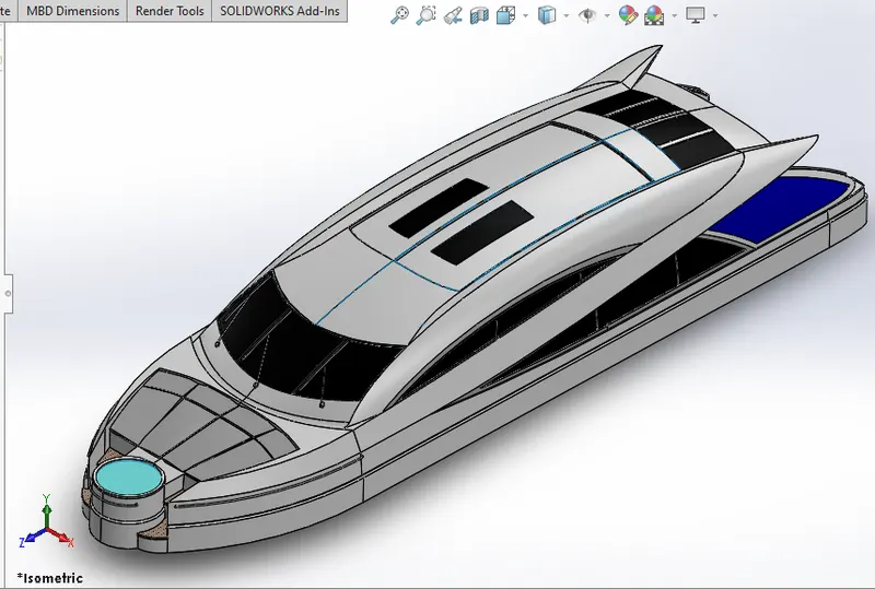
Features used to create Super Structure:-
- 3D Sketch
- Spline
- Center Point Arc
- Swept Surface
- Ruled Surface
- Knit Surface
- Trim Surface
- Extend Surface
- Fill Surface
- Lofted Surface
- Extruded Surface
- Fillet
- Chamfer
PROCEDURE USED TO CREATE A MODEL OF SUPER STRUCTURE:-
-
The deck surface from the hull was imported and the superstructure was modelled over it.
-
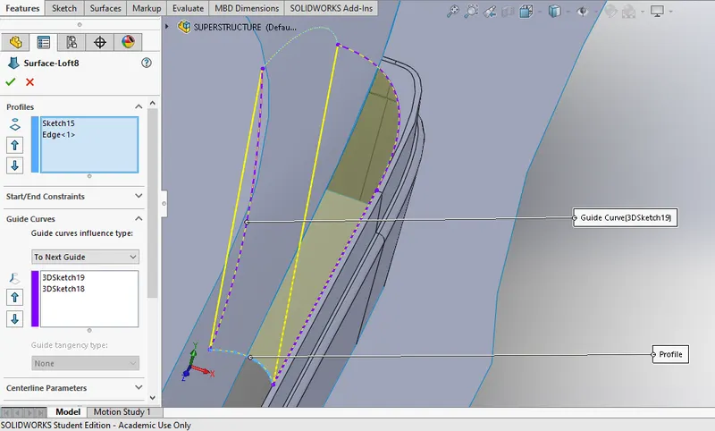
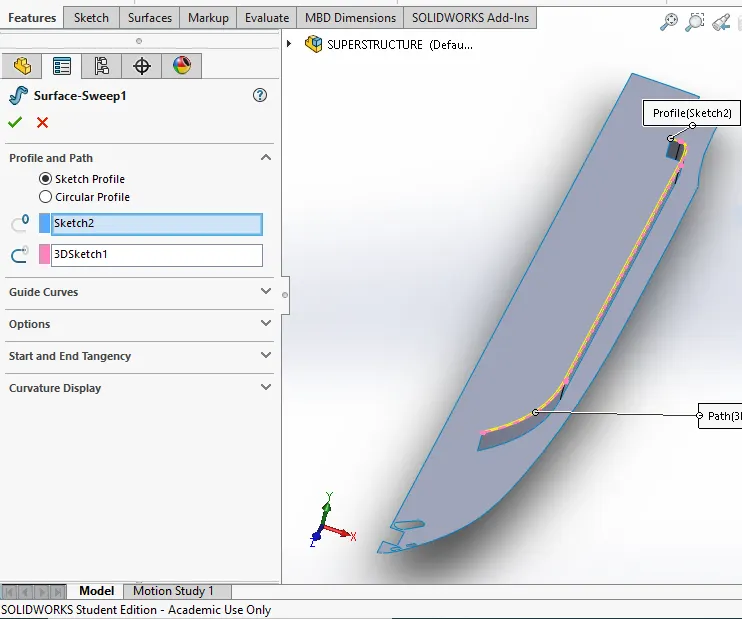
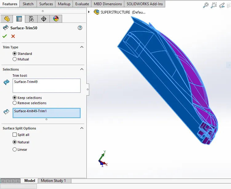
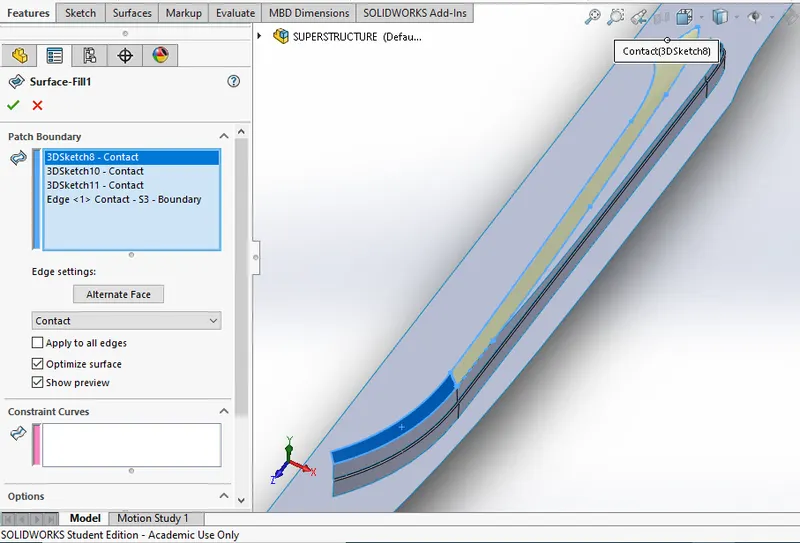
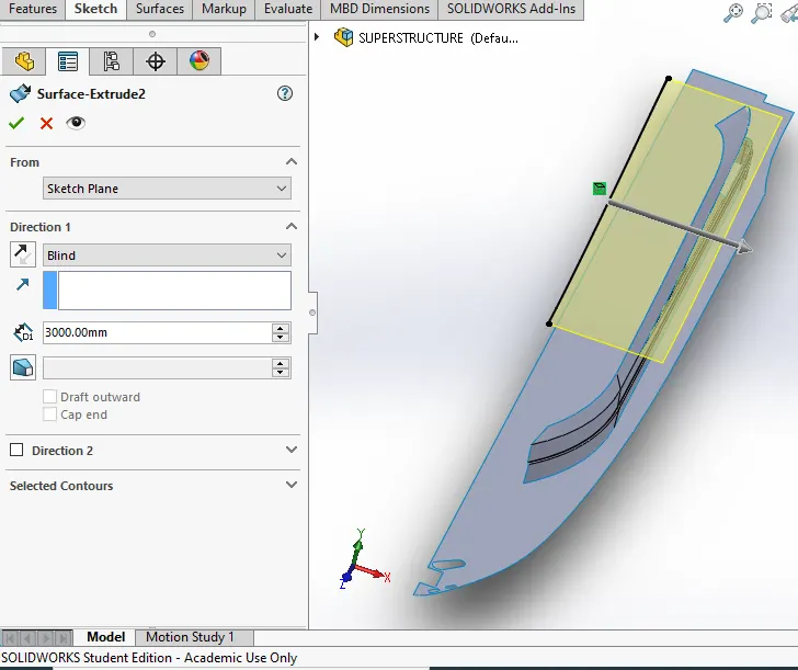
The side surface of the Superstructure was created by using Extruded Surface, Lofted Surface, Filled Surface, Trim Surface and Knit Surface.
-
The Front side of the Superstructure was designed to have four rest beds which were created using Extruded Boss/Base, Fillets and Dome.
-
The front edge of the superstructure was provided with a Water Feature which was created using Extruded Boss/Base, Extruded Cut, and filled with a water appearance.
-
The Windshield was created by Extruded Cut and the wipers were created by using 3D sketch and reference plane with the help of Swept Boss/Base.
- The Portholes for the Superstructure were created by using Extruded Surface, Trim Surface and Extend Surface.
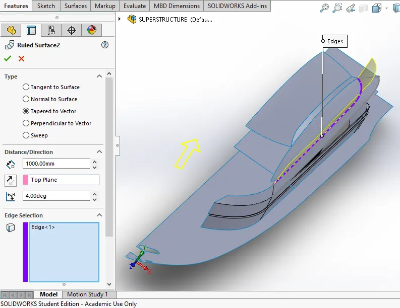
- Ruled Surface was used to fill the left out edges.
- The Back Doors of the Superstructure was created using Extruded Cut, Fillets and Reference Plane.
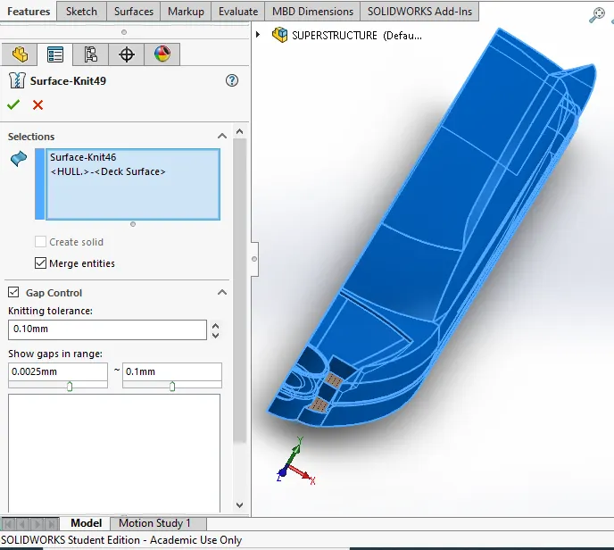
- Then all the surfaces generated were Knitted together to form a solid body. The Superstructure consist of two surface bodies and five solid bodies.
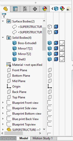
- One of the surface was the Deck Surface the other one was used to place the Radar Mast so it wasrenamed as Radar Mast reference Surface.
- Then the other half was mirrored and the proper fillets and appearance was added and finally the part was saved.
FRONT, MIDDLE & REAR SEAT:-
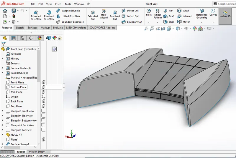
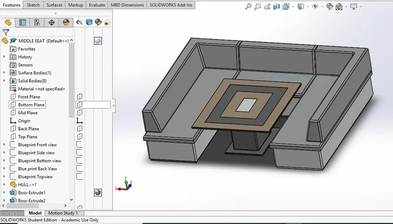
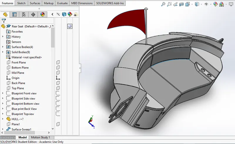
Features used to create Front , Middle & Rear Seat:-
- Trim Surface
- Revolved Surface
- Knit Surface
- Ruled Surface
- Lofted Surface
- Swept Surface
- Offset Surface
- Filled Surface
- Mirror
- Extruded Boss/Base
- Fillets
- Chamfer
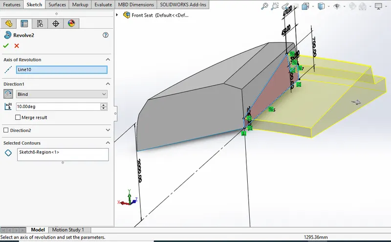
PROCEDURE USED TO CREATE A MODEL OF FRONT, MIDDLE & REAR SEAT:-
FRONT SEAT
- The Front seat of the Yacht was also created with the help of Blueprint.
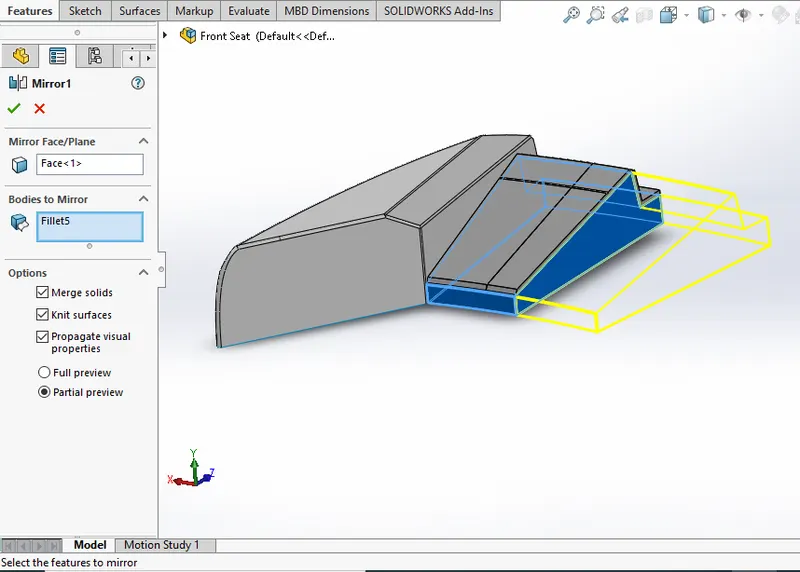
- The first half was modelled and the other half was mirrored using Mirror tool.
- The front seat was placed before the Superstructure facing the Water Feature of the Superstructure and the back end must be placed on the bow of the Yacht.
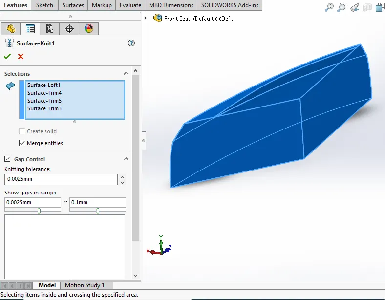
- The body of the Front Seat was modelled using Swept Surface, Extruded Surface, Filled Surface, Lofted surface and the unwanted part was removed using Trim Surface.
- Then the four Rest Beds were created using Extruded Boss/Base and the dome was created over the face of the beds separately.
- Then the required fillets and chamfers were created with extruded thin surfaces.
- Finally the part was saved by adding proper appearances.
MIDDLE SEAT
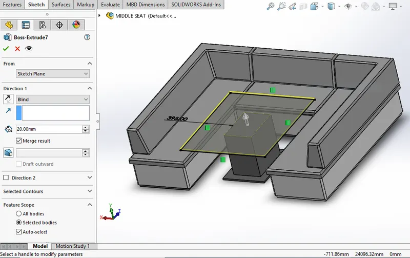
- The Middle Seat was created using the Extruded Boss/Base and by applying the Chamfers and fillets as required.
-
All the surfaces created must be Knitted together by using the Knit Surface option.
-
The Dining Table was also created using Reference Plane, Extruded Boss/base, Off-set, Chamfers andMirror.
-
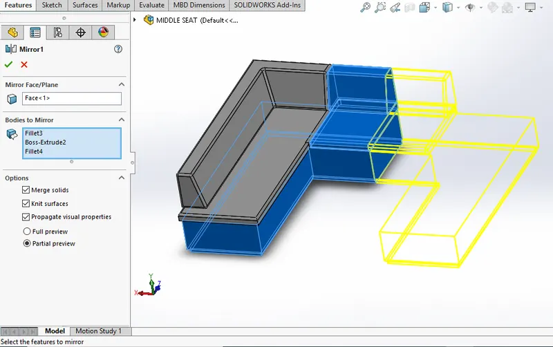
Then the second half of the Middle Seat must be Mirrored symmetrically.
-
Finally the part was saved by applying the proper appearances.
REAR SEAT
-
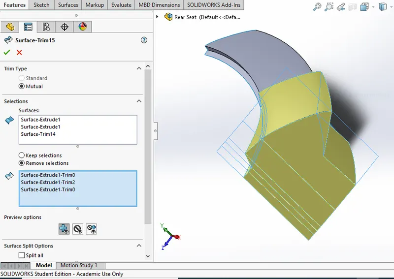
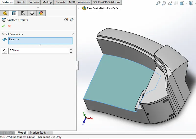
The main body of the Rear Seat was modelled using Swept Surface, Off-set Surface and the remaining portion was trimmed using Trim Surface tool.
-
By using the Reference Plane the Seats were created with the help of Lofted Surface, Surface Trim andExtended Surface.
-
The Flag Post was created using Revolved Boss/Base and the Flag was created by drawing the required 3D sketch and then the 3D sketches were lofted to form the Flag.
-
The Tail Lamps were created by using Extruded Boss/Base, Fillets and Mirror tool.
-
The Steel Gates For Stairs was designed by using the reference plane and the Swept Surface.
-
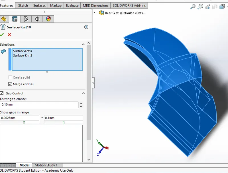
To remove the gaps the all the Surfaces must be Knitted together using Knit Surface.
-
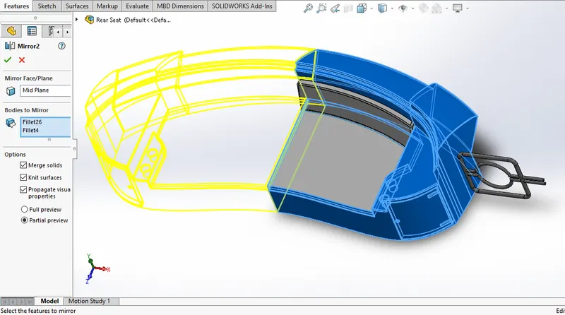
The required fillets and chamfer were created before mirroring the second half using Mirror tool & after mirroring the uncreated areas were filleted again.
- Finally the part was saved by adding Appearances.
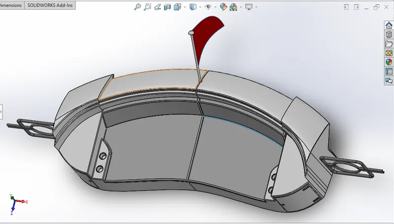
- Projected Curve
- Reference Plane
- Lofted Boss/Base
- Swept Boss/Base
- Revolved Boss/Base
- Extruded Boss/Base
- Mirror
- Dome
- Shell
- Fillet
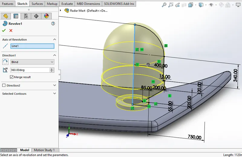
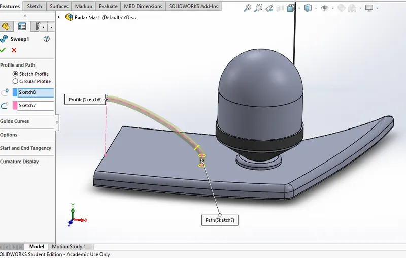
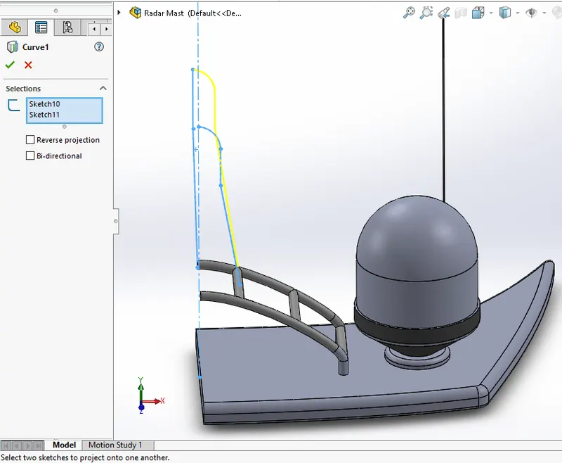
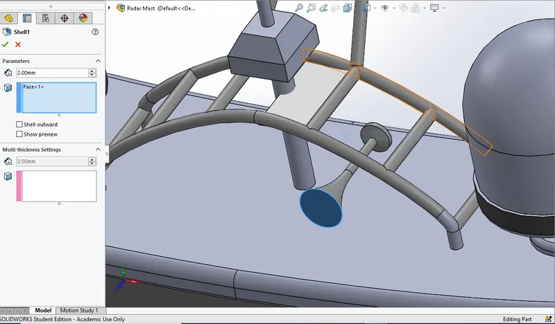
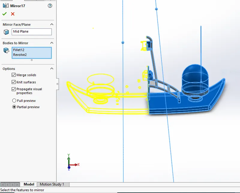
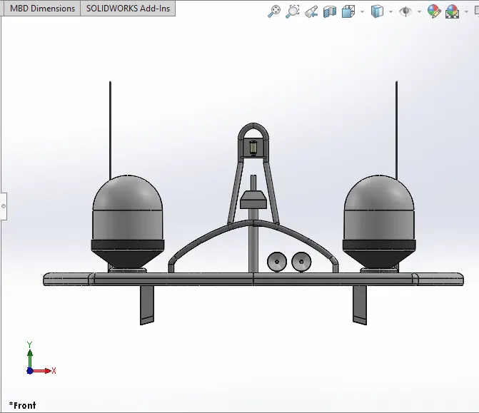
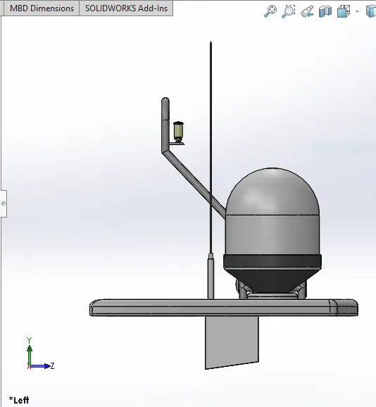
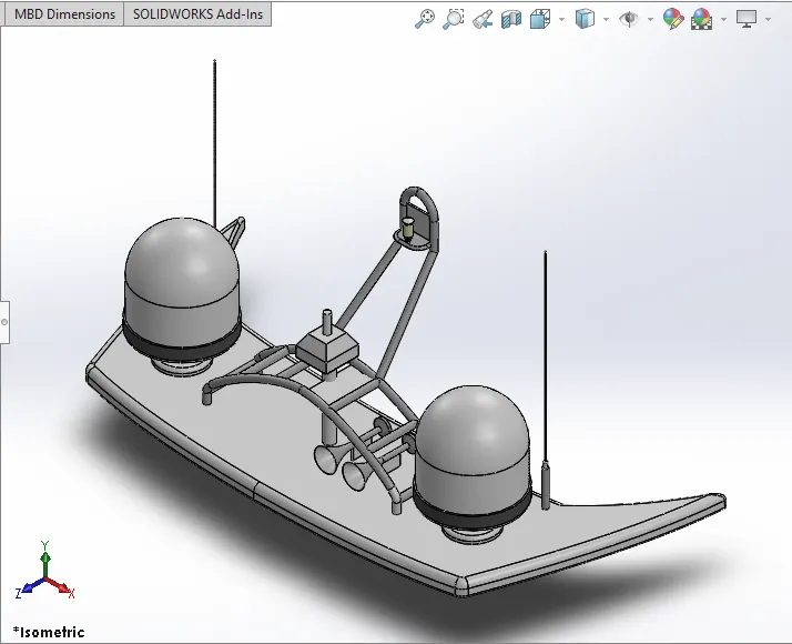
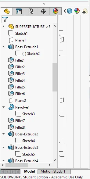
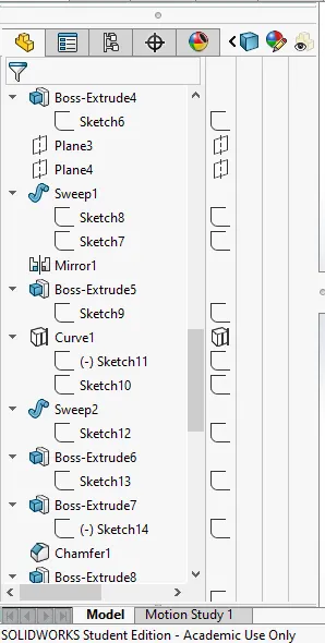
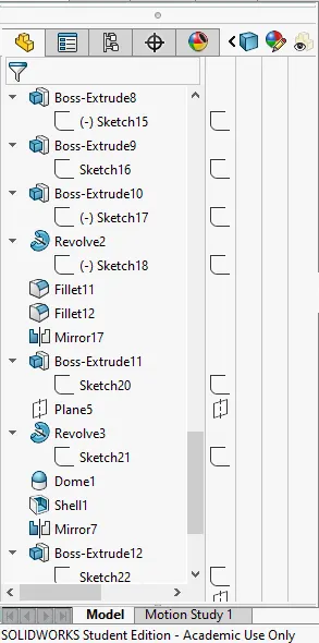
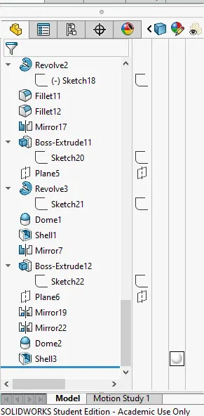
PROCEDURE USED TO CREATE A MODEL OF RADAR MAST:-
-
The first half of the Radar wasModelled with the help of blueprint and then the other half was mirroredwith the help of Mirror tool.
-
The body of the Radar was created using Extruded Boss/Base and Revolved Boss/Base.
-
The antenna for the radar was also created using the Extruded Boss/Base.
-
The lamp stand along with the connecting rod were created using the Swept Boss/Base and Mirror tool.
-
The lamp was created by using the projected curve and then the curve was swept using swept boss/base.
-
The horns were created using the Revolved Boss/Base, Dome and Shell.
-
Then the fillets and chamfers were applied wherever necessary.
-
Finally the part was saved by applying appropriate appearances.
ASSEMBLING:-
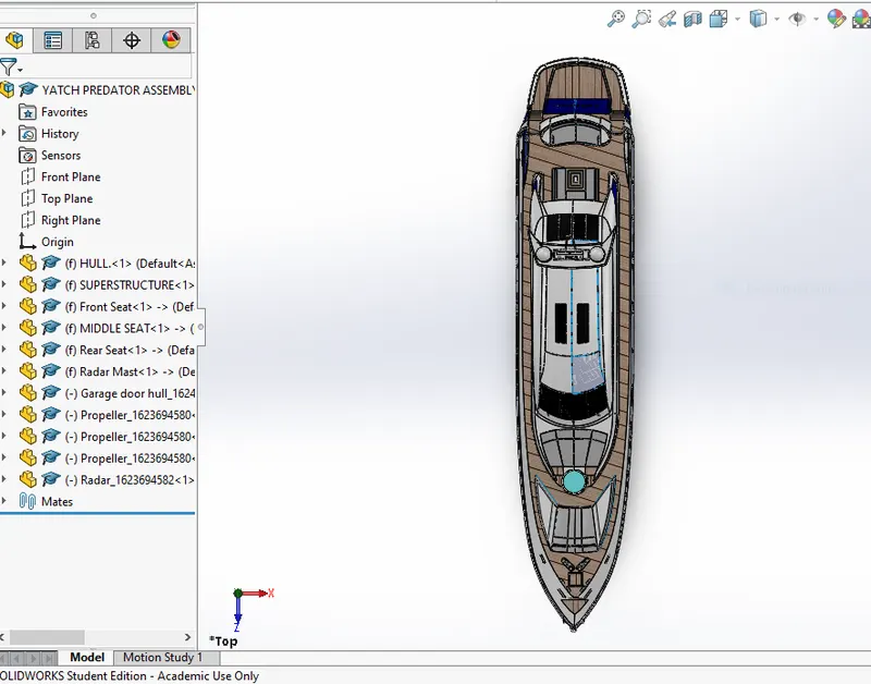
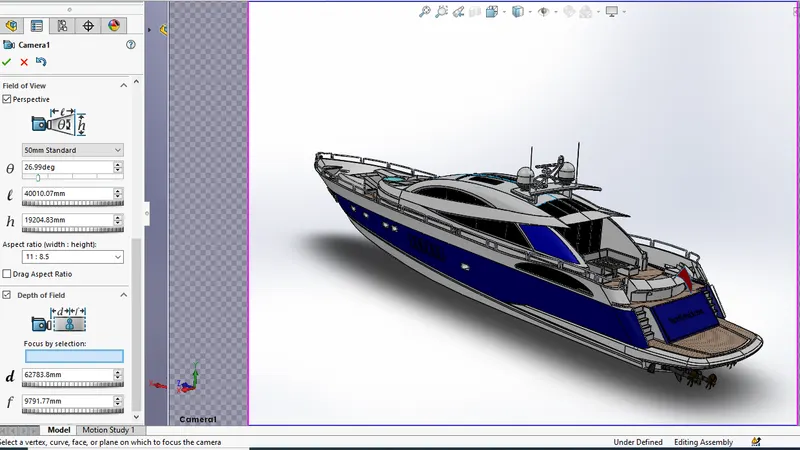
-
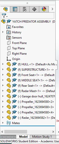
Import all the parts manually by using Insert Components option.
-
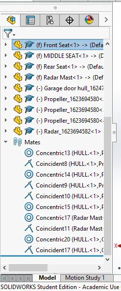
Then fix the Hull part by applying the coincident mate to the Top, Right and Front planes of the Assembly and Hull respectively.
-
Then for each part apply the necessary mates required by the Blueprint using Coincident mates, Angle Mates, Distance mates etc.
-
Advanced mate was also used wherever required.
- Demonstrate products more effectively with full animation of parts, models, appearances, cameras, and environments.
- Import our SOLIDWORKS CAD Motion Studies for truly photographic animations.
- Quickly show off the final design with one-click 360-degree spins
- Create interactive web content such as Interior Panoramas and Exterior VRs.
- Present and compare varying design solutions side-by-side with multiple viewports and included Configurator tool.
- Unleash our creative side with customizable Camera Filters.
- Create new project by importing the required assembly or models into the Solidworks Visualize.
- Add the required appearance, environments, backplates and lights.
- By using the camera tool position the designed model in a realistic view.
- Make sure that the model touches the floor. It can be achieved by using snap to the floor option on Models.
- By applying the required settings the required outputs can be rendered using output tool.
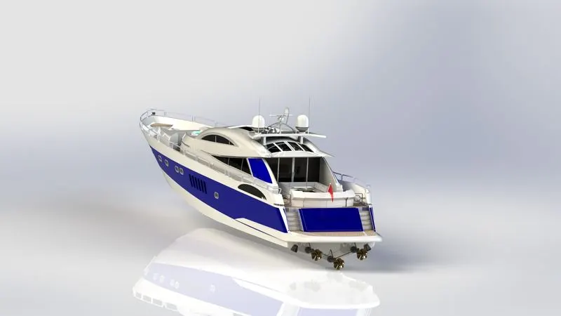
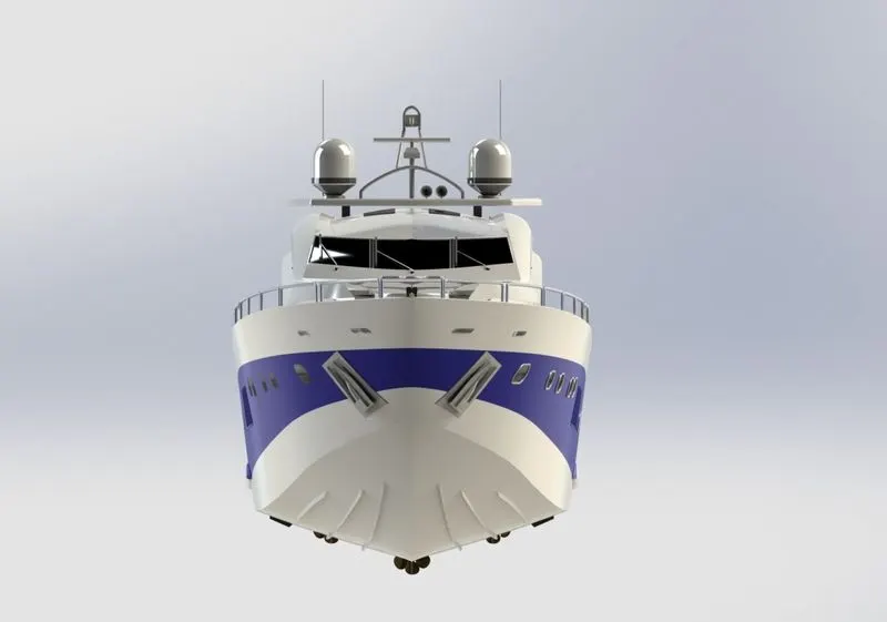
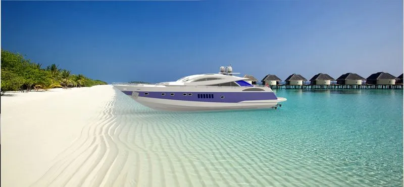
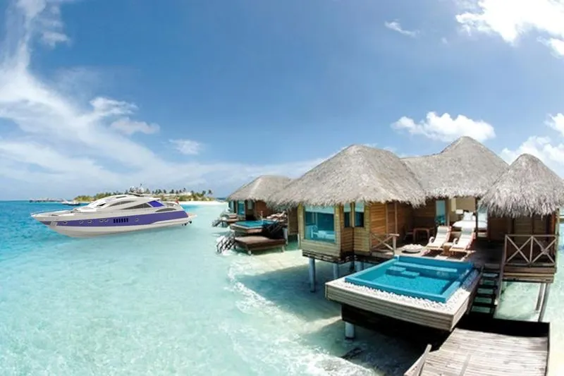
- Thus the project Design & Assembling done successfully.
- Photo-Realistic Rendering of an American Predator Yacht was Modelled and Rendered successfully.