Advanced Sheet Metal Design Using NX Cad Challenge_1_Casing Design
CASING DESIGN SHEET METAL
OBJECTIVE
To Design a Sheet Metal Casing using NX CAD
INTRODUCTION
NX sheet metal design software incorporates material and process information in sheet metal-specific modeling features: bends, flanges, tabs, cutouts, beads, dimples, louvers, corner and edge treatments, patterns and other formable features. You can also quickly convert solid models to sheet metal components, and create sheet metal parts that enclose other components.
NX Sheet Metal-specific features such as flanges, tabs, jogs, corner conditions, and drawn cutouts & many more along with productivity enhancements such as – automatic bend reliefs.
The software also provides common modeling features typically used in sheet metal design, such as holes and slots, as well as other essential capabilities such as copy, paste, and mirror.
The application provides defaults for sheet-metal-specific properties such as material – thickness, bend radius, and bend relief. You can easily change these defaults.
APPROACH
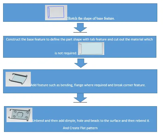
FEATURES USED:-
- SKETCH: This is used to createa basic sketch of the design on selecting the desired plane, then later it can be modeled for the requirement.
-
TAB: This feature is used to create a base tab on selecting the curve drawn in sketch mode with theappropriate thickness on our desire and it can easily convert that sketch into the sheet.
-
NORMAL CUTOUT: This feature is used to cut the portions of the sheet metal by assigning sketch curves.
-
BEND: This feature is used to bend the sheet metal along the sketched curve upon our requirement.
- FLANGE: Flange is used to add flanges on selecting the edges of our sheet metal, it is working as a BEND feature along with that extra material can be added by adjusting the length of the flange.
- BREAK CORNERS: Break corners are used to make the edges round for easy handling when using.
- UNBEND: Unbend is a feature used to analyze the model whether a part was perfectly assigned the features, which ensures for a modeler to do further operations on it.
- HOLE: It is actually used for making the holes on the requirement foor further assembly of the part by assigning different types of specifications of screws.
- DIMPLE: It is used to draw a dimple on selecting a curve for modeling the sheet.
- BEADS: This feature is used to create a bead on the sheet which generally strengthens it.
- MIRROR:It is used to add the material or feature replicates by acting as a mirror to it, this generally reduces the modeling time.
- REBEND: This is used to re-bend the object after all conformatioons and ready for production.
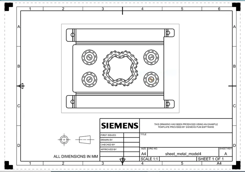
- DRAFTING: It is used to provide the dimensions and views of the designed part to the manufacturing team.
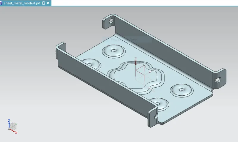
FINAL CAD MODEL OF SHEET METAL CASING
- ISOMETRIC VIEW
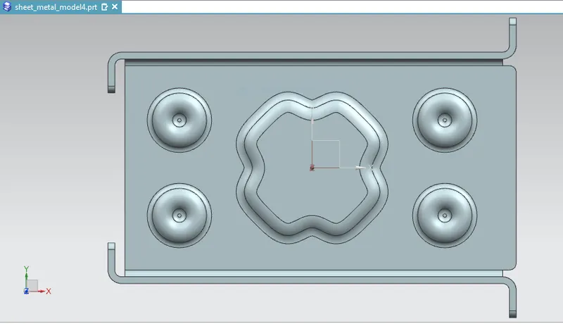
- TOP VIEW
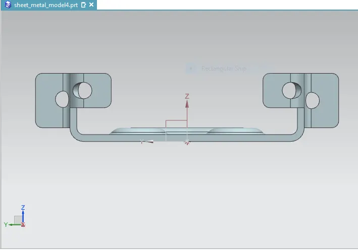
- FRONT VIEW
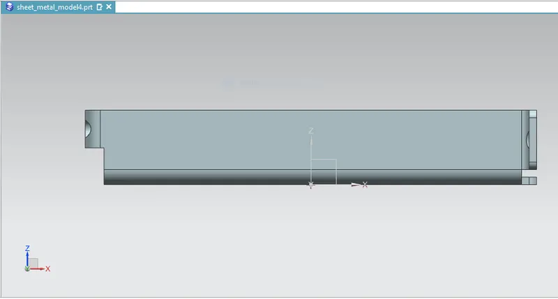
- SIDE VIEW
DRAWING SHEET
CONCLUSION