Week 8 - Challenge 1 - Base Bracket Design
Base Bracket Design
Aim:
Create the Base Bracket Plastic component through the given Class-A surface. To begin with, the tooling axis for the given Class-A Surface should be created meeting the requirements of the draft angle and at the end perform the Draft analysis on the model.
Objectives:
- A detailed report should be done explaining the draft analysis and the tooling axis creation.
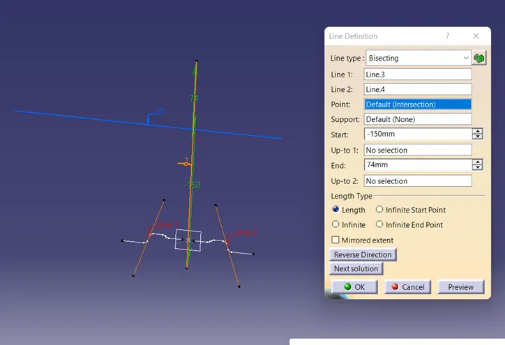
- An explanation should be given on the way of creating the tooling axis, particularly the Bisecting method.
REPORT:
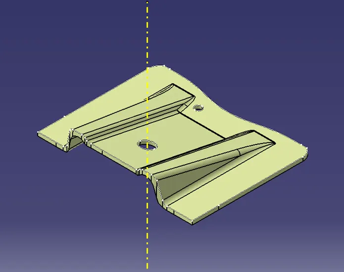
CLASS A SURFACE: Class A surface is a surface made by the designer specially in automotive design which is the aesthetic part of a body and is given as an input to the plastic designer to work on it.
CLASS B SURFACE: It is a surface which comes below the class A surface with a particular thickness. This surface contains engineering features of a model like bosses, ribs etc.
CLASS C SURFACE: It is the surface which joins class A with class b surface.
TOOLING AXIS: The mold is built in two separate pieces, basically. You have a Cavity side and you have the Core side. The Core pulls apart from the Cavity and that's the Dyeline or the Tooling Direction. Again, depending upon where you're working at, you may have a different name for it. So, when you go in and you create that Tooling Direction, you want to make sure that whatever you create is going to be used as a reference to design your data up against. So, when you add in your ribs, maybe some pockets, walls, whatever that may be, bosses, the walls are going to be drafted based off of the Tooling Direction. It's to make sure that the Core can pull apart from the Cavity, nice and clean.
Creation of tooling axis using Bisecting method:
Step 1: Rotate the model and finds the surfaces that are inclined and are supposed to affect the tooling axis of a component.
Step 2: By using intersection tool, a curve is obtained from the intersection of the plane we choose and the surface selected.
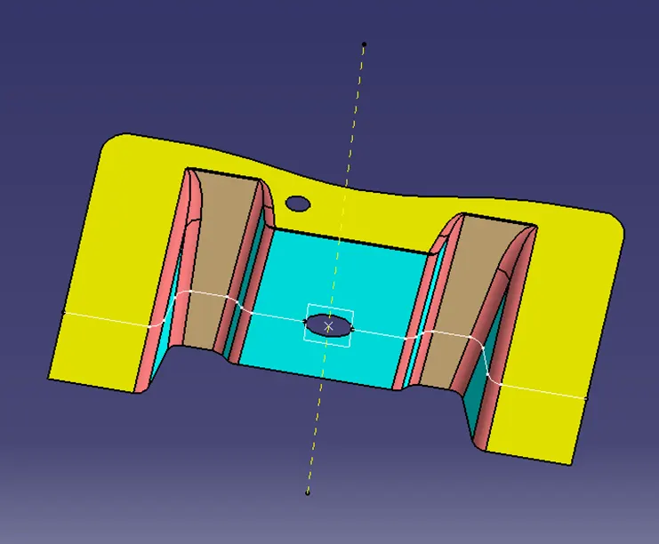
Step 3: From the curve, the inclined lines are opted as they feel to affect the tooling axis and from the end points, a line is created using point-point option in line definition.
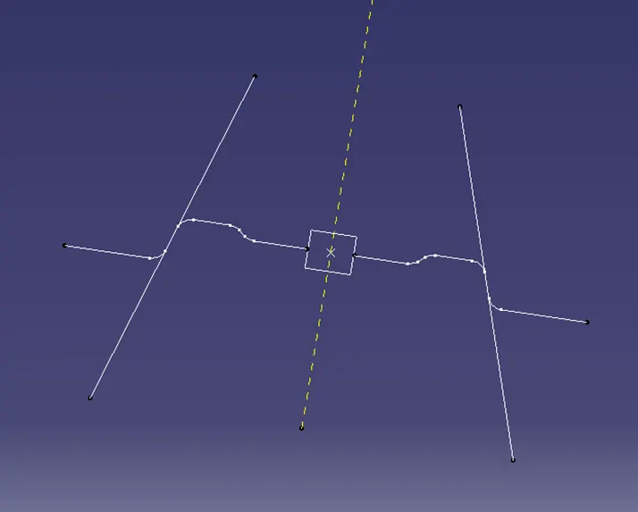
Step 4: Bisecting line is drawn from the two inclined lines by opting bisecting from line definition. Thus, tooling axis is obtained.
Procedure For The Creation Of Closed Surface
- Class A surface is obtained as the input.
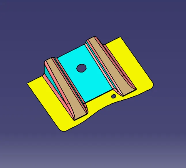
- Tooling axis is created using the Bisecting method which is already explained.
- Now, Class B surface has to be created. For this, flat surfaces of class A surface is extracted.
- Extracted surfaces are later untrimmed and offset to 2.5 mm.
- Extrapolated the offset surfaces and later performed trim command to obtain the surface which is needed.
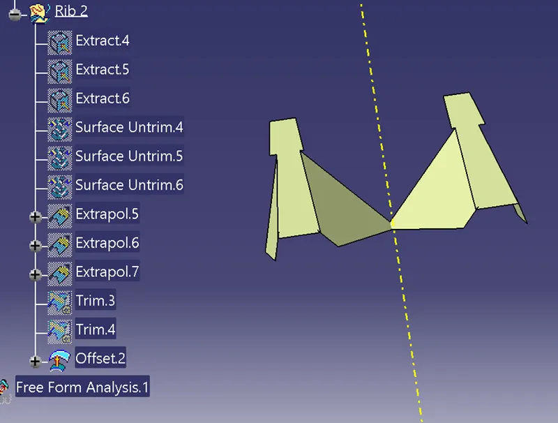
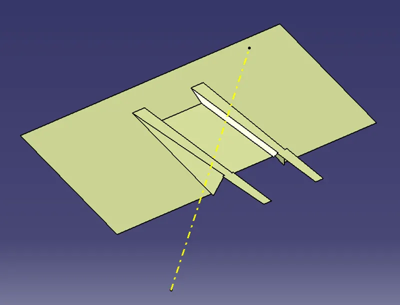
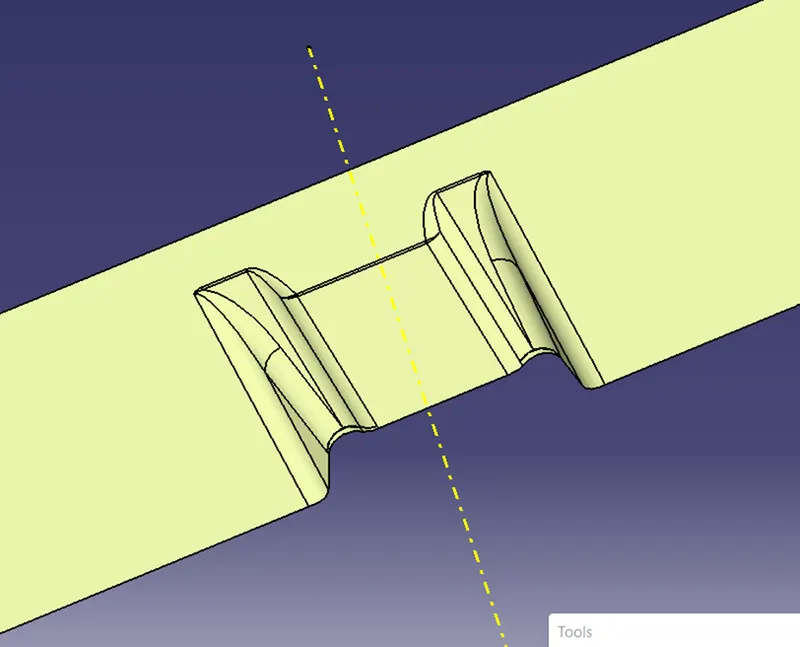
- Fillets are measured from the Class A surfaces and appropriate fillets are provided for Class B surface by adding or subtracting the thickness of the component to obtain correct thickness everywhere.
- Class C surface is created using the boundary of the class A surface followed by sweeping it with the tooling axis direction with a draft of 3 degrees.
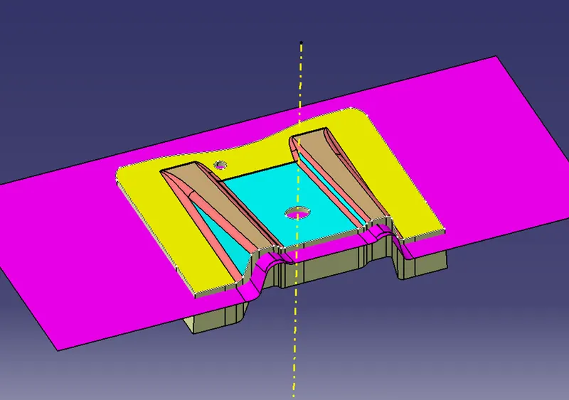
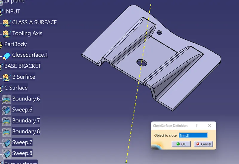
- Class A and Class B surface is trimmed with the class C surface after performing the join command.
- Closed surface command is performed with the help of part workbench and later the draft analysis is performed.
Draft in injection molding
Draft is a taper applied to the faces of the part that prevent them from being parallel to the motion of the mold opening. This keeps the part from being damaged due to the scraping as the part is ejected out of the mold. Adding draft to an enclosure can create issues if it isn’t applied correctly. When applying draft to the inside and outside walls, design these walls parallel to each other to avoid deep ribs in the mold that make venting, ejection, mold finishing, and manufacturing more difficult. Consider a core-cavity approach to design as this opens up the mold cavity and core for polishing, accelerates manufacturing speed and, in general, brings added ease during the molding process.
Draft Analysis
For molded or cast parts, the draft angle is the amount of taper perpendicular to the parting line. It is measurable in degrees. Because plastic shrinks and sticks on molding surfaces as it cools, we draft the walls of the plastic part so that it ejects or breaks free from the molding surfaces more easily and without dragging. To reduce the risk of damage to the parts and ensure ejection, a functional injection molding part must have drafts on both the cavity and core sides.
Nominal values for Draft angles
- 3 Degrees is a nominal draft angle
- 5 Degrees can also be manufactured. Increasing the manufacturing cost
- 7 Degrees is considered for Textured surface parts
Importance of Draft in injection molding
- Reduces the possibility of part damage due to friction during the release
- Reduces mold wear and tear
- Ensures a uniform, smooth, unscratched finish
- Ensures the integrity and uniformity of other surface finishes and textures
- Reduces overall cooling time by reducing or eliminating the need for unusual ejection setups
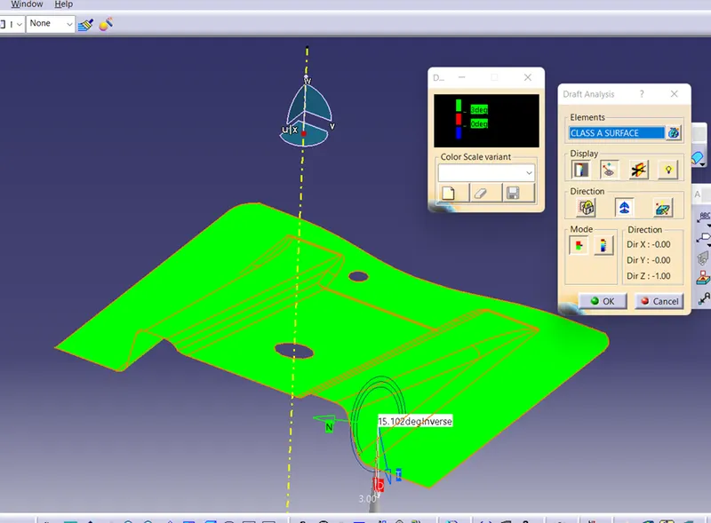
CLASS A SURFACE Draft analysis report:
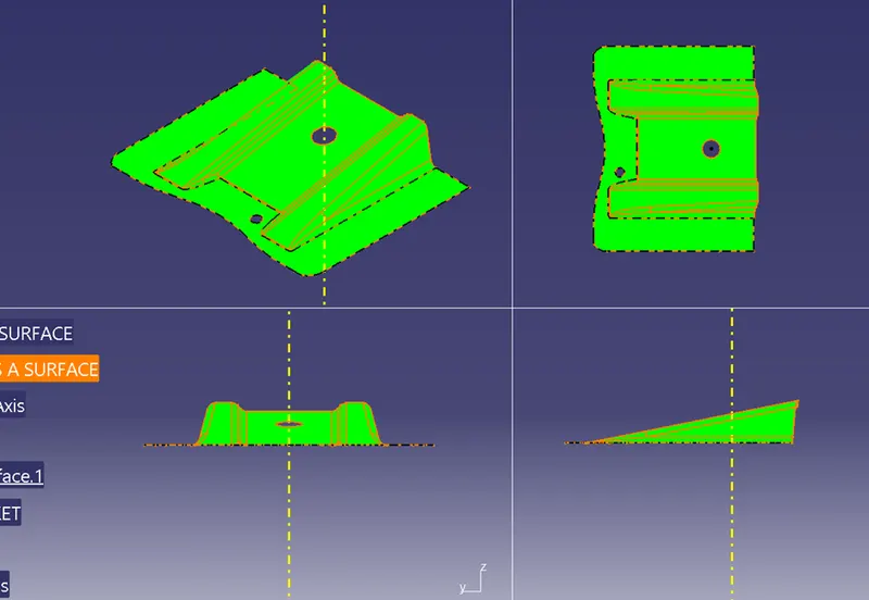
Draft Analysis of Close surface
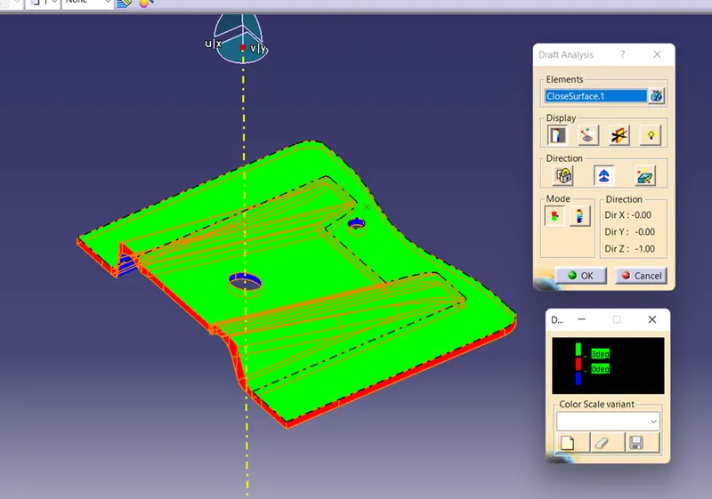
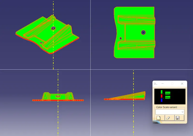
Steps followed for Draft Analysis
- The created part must be changed to the material mode in the display frame
- Compass is enabled and placed in the direction of the Tooling Axis
- The lock command is then used to fix the compass along the tooling axis