Week 9 - Attachment Feature Creation (Ribs & Screw Boss) - Challenge 1
|
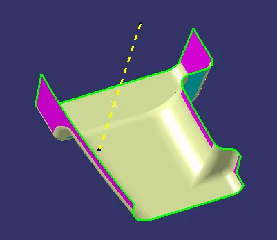
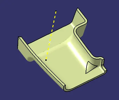
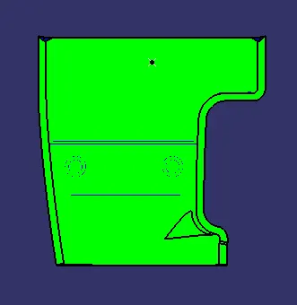
AIM: To create rib and screw boss for the drill handle considering the standard design rules. Creation of tooling axis: The given class-A surface of the drill handle is carefully analysed for any surface defects and then after studying the geometry of the given class-A carefully, the tooling axis is determined. For the given class-A the tooling axis can be considered normal to the surface of the class-A in the Y-direction as the given surface mainly consists of fairly flat surfaces. This can be done by simply creating a line in the Y-direction through a point on the flat surface of the class-A.
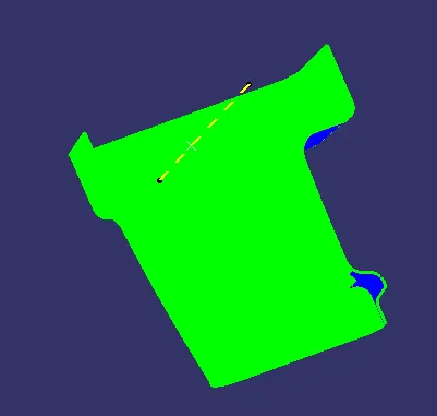
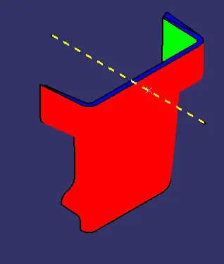
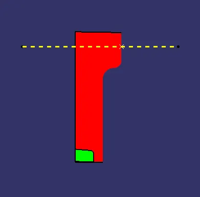
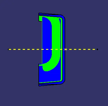
Draft Analysis on Class-A Surface Draft analysis on the given class-A is carried out to check if the given component is manufacturable and ejected out in the drafted tooling direction. To do so, the ‘Feature Draft Analysis’ option is selected from the ‘Analysis’ section of the ‘Insert’ tab in the ‘Generative Shape Design’ workbench from the GUI of the software. Prior to that, the ‘Customize View’ is kept in the ‘Material’ mode. Later the Tolling direction is fixed and the draft analysis output is obtained by giving the required draft angle. If there are no ‘Red’ portions on the class-A in the Analysis report, then it can be concluded that the surface is manufacturable.
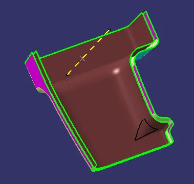
Creation of Class-B Surface The class-B surface is a secondary surface which is not seen by the eye when we see a component such as the inside of a glove box, lower surface of the base bracket etc. So to crate the class-B surface the entire class-A input is offset to the required thickness of the component. Sometimes it may not be possible to offset the entire A-surface to the required value due to some computation errors. In such cases the gaps in the offset B surface can be filled using different options such as fill, sweep, multi-section solid etc. The surface finally obtained will be the required class-B. And for the given drill handle, the class-B surface is obtained by offsetting the input surface to 3mm since the thickness of the component is not given, assume the standard thickness value for the plastic component).
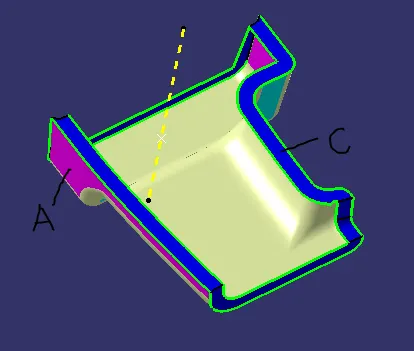
Creation of Class-C Surface Class-C is a non-aesthetic surface which connects the class-A and class-B surfaces. The C surface connects the class-A to the class-B surface and usually represents the thickness of the component. It is created from the boundary of the given class-A surface. The boundary of the class-A id extracted and swept with respect to the tooling axis considering its manufacturability and the surface thus created represents the C surface.
Creation of Solid CAD Component Initially the class-A and the C surfaces are joined together. Then the joined surface is trimmed with the class-B surface so that a closed surface of the actual component is obtained but it is still hollow. Then to obtain the actual solid component we go to the ‘Part Design’ workbench and then select the ‘Close Surface’ feature on the hollow surface to obtain the required solid component.
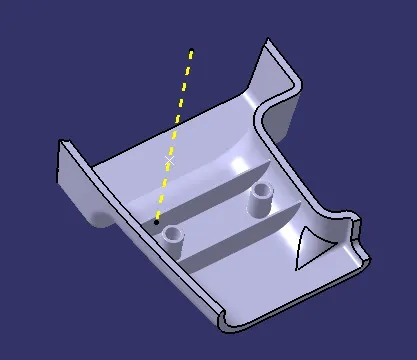
Creation of Attachments (Ribs and Screw Bosses) To create a ‘Rib’, a base surface is selected and then extracted. On this base surface a line to the required dimension and position is created using position sketch feature and then extruded normal to the base to the required rib height. This extruded surface is thickened to the required value as in standard design procedure. The feature is then added to the component body using Boolean operations and then the side faces are draft in the tooling direction keeping standard design considerations in mind. Using another positioned sketch on the extracted base surface, the screw boss is sketched at the required position and extruded to the required height considering the design considerations as was the case with the rib. Then the body of the screw boss is added to the component body using suitable Boolean operation and the actual component with the attachment features is obtained.
Draft Analysis on CAD Model The draft analysis on the final CAD model of the component is carried out in the same way as done on the class-A surface and checked if the component is manufacturable in the tooling direction selected.
|