Week 8 - Challenge 1 - Base Bracket Design
BASE BRACKET DESIGN
Aim:
To Create the Base Bracket Plastic component through the given Class-A surface and perform Draft Analysis on the final plastic component.
Objectives:
- Creation of Tooling Axis.
- Creation of Class B and Class C surface.
- Creating a solid part out of surface modelling.
- Draft Analysis of Class A surface and final plastic component.
Tool Used:CATIA V5
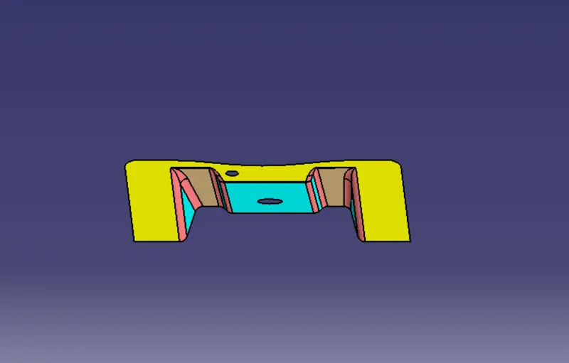
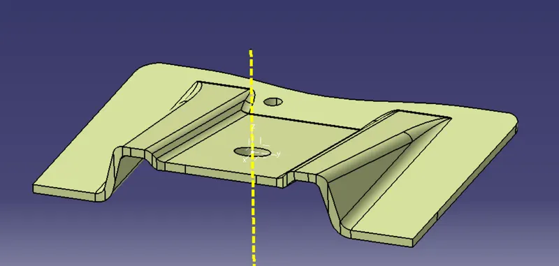
Given Class A
Creation Of Tooling Axis:
To continue the designing process we need create the tooling axis first for the surface.
- By creating a intersection of class A surface with zx plane and from the intersection create a bisecting line as shown below.
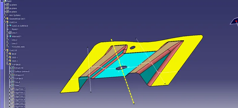
here the Dotted yellow line is the Tooling axis for the surface.
Creation Of Class B
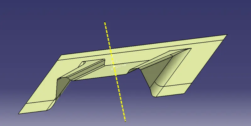
By extracting surface from class A and untrimming them to get a surface and these surfaces are then offsetted to required thickness.After offsetting all are trimmed and required fillets are given to the surfaces.
Creation Of Class C

Using Multi extracting the boundary of class A and then it is converted to smooth curve and the smooth curve is swept along the draft direction with a 3deg draft.
CLASS A+CLASS C Creation
By Using Join command the class A surface and the class C surface made is joined to create a single body.
Class A+Class B+Class C Creation
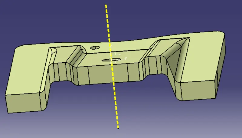
By Trimming the joined Class A & C surface with class B the Class A+Class B+Class C is created.
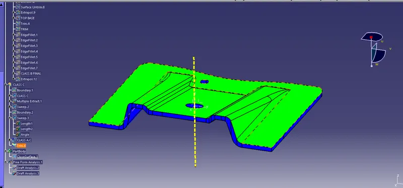
Draft Analysis on the Final Component
Taking tooling axis as reference draft analysis is carried out:
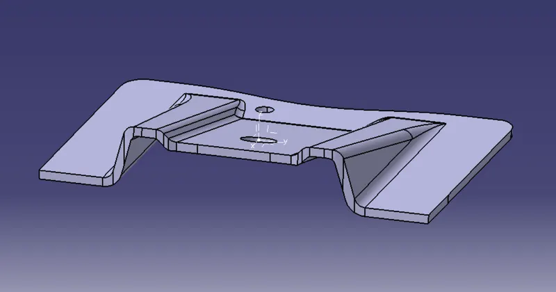
FINAL SOLID
CONCLUSION
The Base Bracket Plastic component is designed from given Class-A surface and performed Draft Analysis on the final plastic component.
***************************************************************************************************************************************************************************************************