Week -2
1.To Make a Simulink model of Doorbell Using Solenoid Block where the switch is closed for 2second and then released.
Door Bell Mechanism:
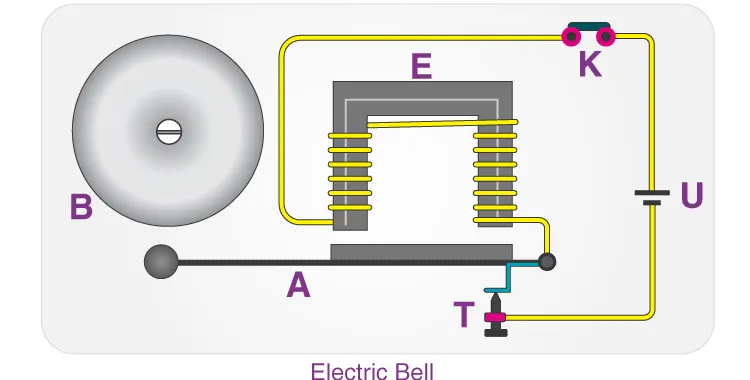
The above image shows the internal mechanism of an Electric Doorbell.The electric circuit is completed by installing a push switch which you can press to produce sound in an electric bell.This switch also act as an circuit breaker.
So once the setup is completed,when the switch is pressed the circuit loop is complete which causes the current to flow through the circuit.The arm which strikes the gong is connected to spring at one end and at an iron ball at the other end.This is called a hammer or a striker.The arm is attached to the iron strip which is attracted to the electromagnet when the circuit is complete and the current flowing through it.When an electrical current flows through this wire,a strong magnetic field/flux is created.
SIMULINK MODEL
The input given to pulse generator block is given:
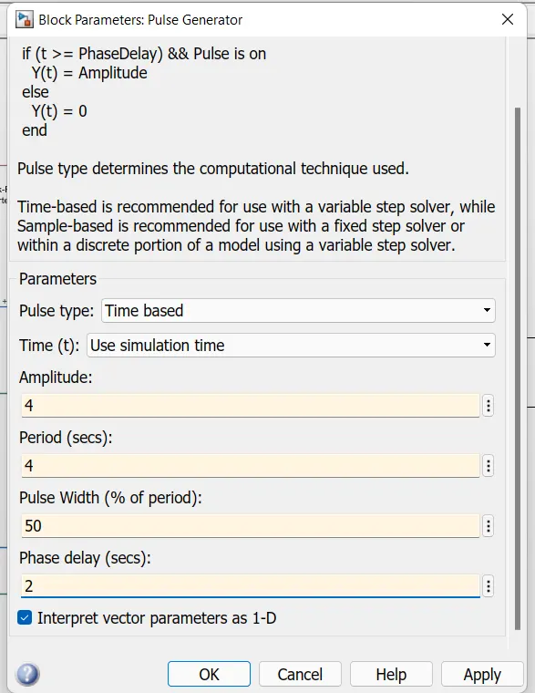
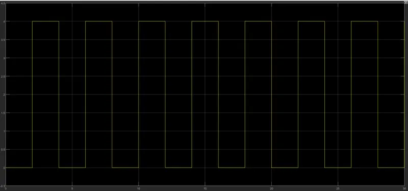
To get 2seconds of phase delay and 2seconds to ring,the time period is given as 4seconds with pulse width of50%.
Then Scope is used to see the graph
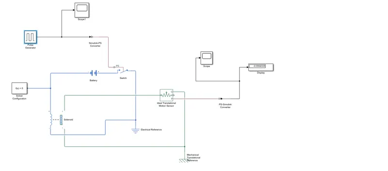
- Simulink-PS convertor is used to convert signal input to physical sysytem and given to switch block.
- Battery,switch and solenoid block are connected each other.
- The scope is connected to an ideal translation motion sensor to see the output graph
OUTPUT
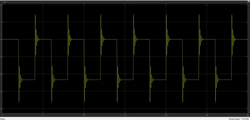
From the above output we can see that switch is closed for 2sec after that switch is released.
------------------------------------------------------------------------------------------------------------------------------------------------------------------------------------------------------------------------------------------
2.To use a thermistor to sense the temperature of a heater and turn ON the fan if the temperature is above 25 degree C and off Otherwise.
THERMISTOR:
A Thermistor is a resistance thermometer or a resistor whose resistance is dependant on temperature.
The thermistor works on the simple principle of change in resistance due to change in temperature.When the ambient temperature changes the thermistor starts self heating its elements.its resistance value is changed with respect to change in temperature.This change depends on types of thermistor Used.
There are two types of thermistors:
- Negative Temperature Coefficient(NTC)thermistor
- Positive Temperature Coefficient(PTC) thermistor
In an NTC Thermistor, temperature and resistance are inversely Proportional and In an PTC thermistor temperature and resistance are directly proportional.
SIMULINK MODEL:
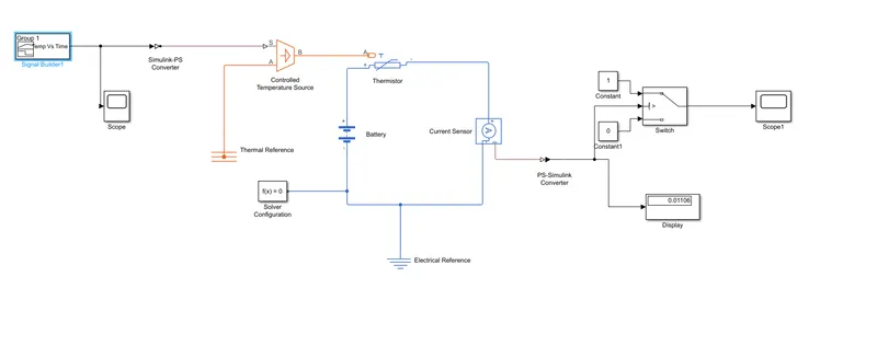
Signal Buider,Simulink-PS Convertor,controlled temperature source,Thermal reference,Thermistor,Battery,Voltage sensor,Electrical Reference,Solver Configuration,PS-Simulink Convertor,switch,constant,Display and Scope are the different Blocks used in this simulink model.
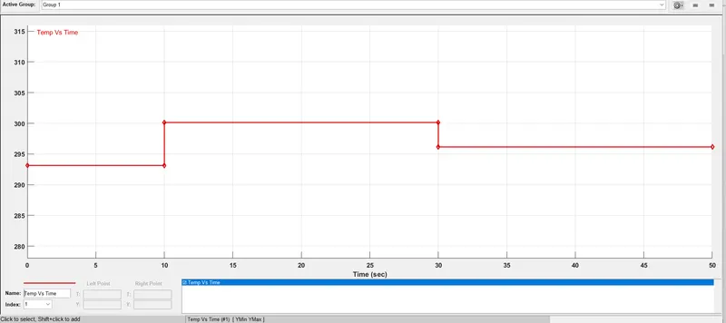
- The input here is fed through the 'Signal Builder' block.The data given is based on the conditions in the challenge.
Temperature Source:20degree C from 0-10sec,27degree C from 10-30sec,23degree from 30-50sec.
Fan conditions:ON if the temperature above 25degree C,OFF otherwise.
- All the temperature in celsius is converted to Kelvin so,
0-10sec-293.15K
10-30sec-300.15K
30-50sec-296.15K
The input given to signal builder block is
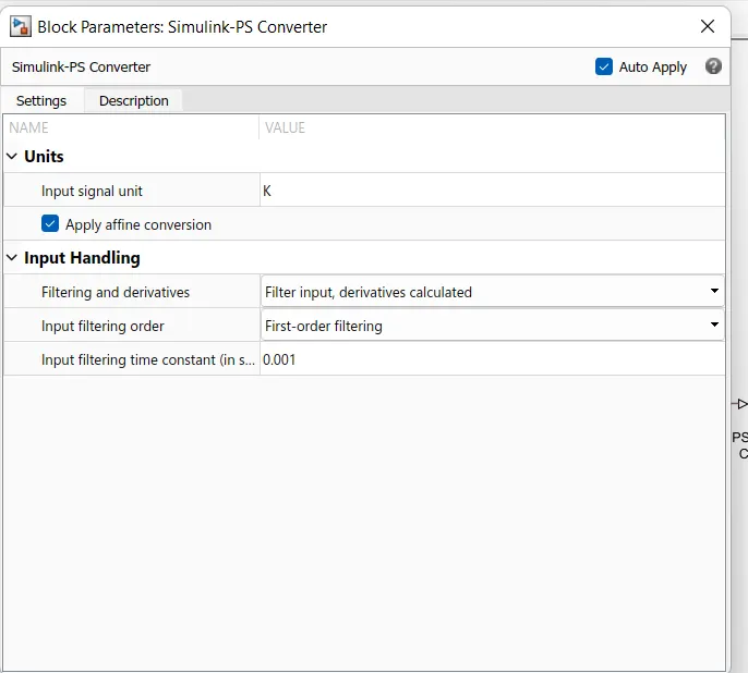
Also because of the kelvin conversion,we should change the parameters in signal convertor,
- The port T of thermistor block is connected to a controlled temperature source
- one port of thermistor is connected to the thermal reference and another port is connected to simulink-PS convertor.
- The signal Builder block having the temperature in kelvin give the input data.
- The Positive side of thermistor is connected to the positive terminal of battery and negative side to the current sensor and also a electrical reference is provided.
- The value from current sensor is converted into simulink signal using the PS-simulink convertor.
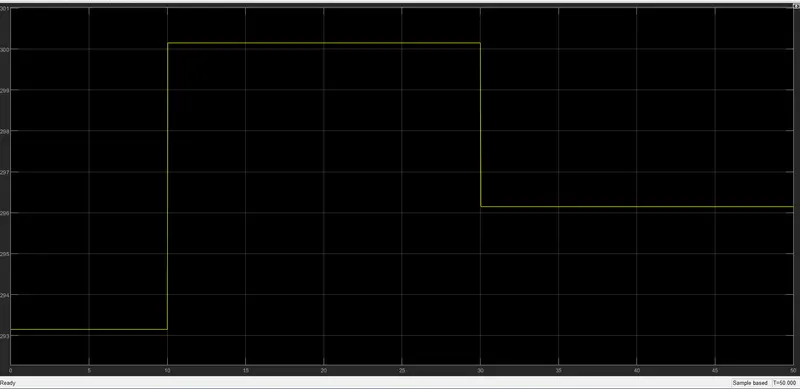
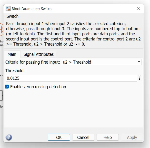
- Inside the switch has 2outputs based on two conditions,
if the value is above threshold value of output will be 1 and if it is below it will be zero.
- in the final stage scope is connected to see output for fan on or off.
SIMULATION RUN TIME 50SEC.
FINAL OUTPUT
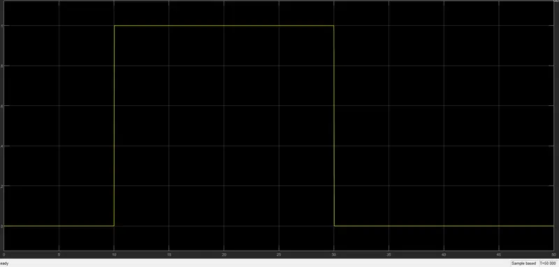
- From 0-10sec signal is '0' , 10-30 sec signal is '1' and 30-50sec ahain it is '0'.
So,
From the above output we can say that on the given conditions the fan should work only in time period of 10-30 seconds.
-------------------------------------------------------------------------------------------------------------------------------------------------------------------------------------------------------------------------------