Project
AIM:
To Study and analyze the BAJA All-Terrain Vehicle model using Simulink.
Objectives:
- To prepare a technical report explaining the model properties and blocks used to create the model.
- To Understand and comment the results.
Types of Models Studied:
- BAJA ATV model without dashboard(cvtModel)
- BAJA ATV model-Data Extraction(cvtModel_data)
- BAJA ATV model with Dashboard(cvtModel_dashboard)
- BAJA ATV model-Mapped Lookup Table without Dashboard(cvtModel_mapped)
- BAJA ATV model-Mapped Lookup Table with Dashboard(cvtModel_dashboard_mapped)
ALL TERRAIN VEHICLE
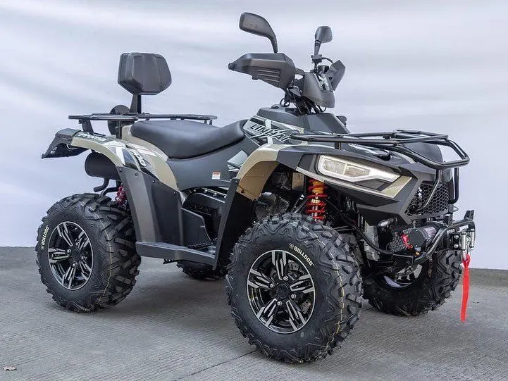
An All Terrain Vehicle also known as light Utility Vehicle is a vehicle that travels on low pressure tyres,with a seat that is straddled by the operator along with the handlebars for steering control.As the name implies,its is designed to handle a wider variety of terrains like hilly,rocky,muddy,lose gravel,mountainous areas etc. than most other vehicles.
It is specially designed for Off road usage.There are different types of ATVs are there based on the design and usage.some of them are Sport ATVs,Utility ATVs,Side by Side ATV s,Youth ATVs etc.
BAJA ATV
BAJA is basically an ATV competition where students get to design and develop their own ATV Keeping in mind various considerations of design as well as safety.
BAJA SAE

BAJA SAE is an inter collegiate design series competition run by the SOCIETY OF AUTOMOTIVE ENGINEERS(SAE INTERNATIONAL).Teams of students from universities all over the world design and make small off road cars.The cars all have engine of the same specifications.
The Goal in BAJA SAE racing is to design,build and race off road vehicles that can withstand the harshest elements of rough terrain.
CONTINOUSLY VARIABLE TRANSMISSION(CVT)
A CONTINOUSLY VARIABLE TRASMISSION(CVT) is an automatic transmission that can change seamlessly through a continuous range of gear ratios .This contrasts with other transmissions that provide a limited number of gear ratios in fixed steps. The flexibility of a CVT with suitable control may allow the engine to operate at a constant RPM while the vehicle moves at varying speeds.
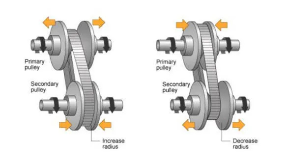
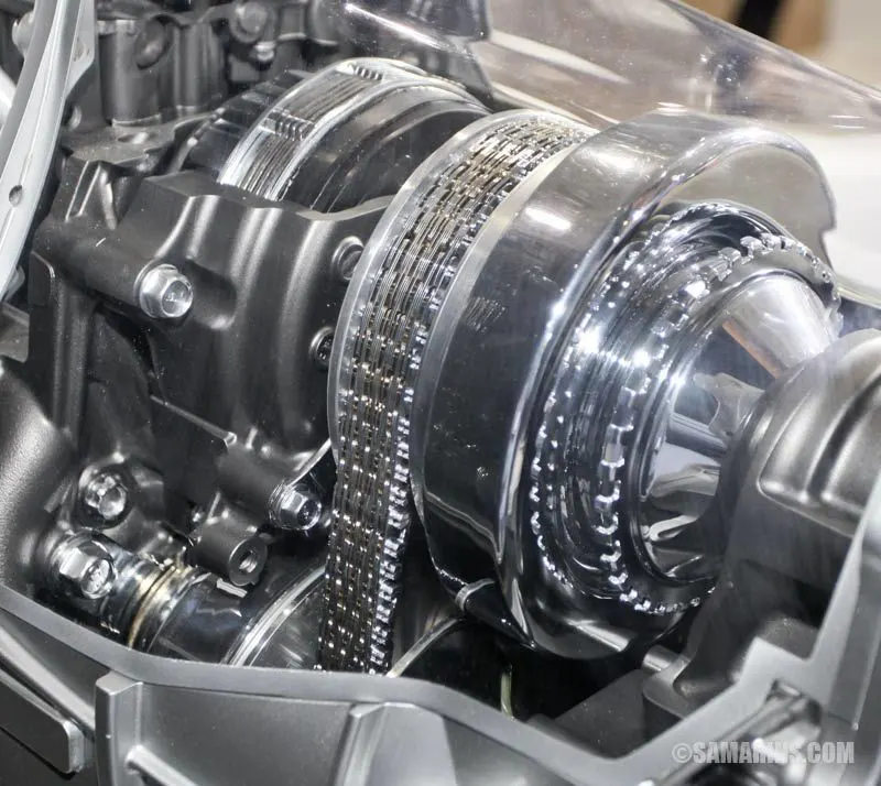
Depending on the vehicle and the driver,a CVT can provide a smoother driving experience when comparing it to the traditional automatic.
Main Blocks Used In the Models
Simple Gear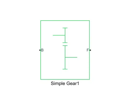
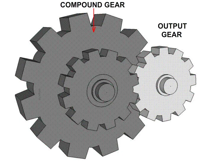
The Simple Gear Block represents a gearbox that constarins the connected driveline axes of the base gear'B'and the following gear'F' to co rotate with a fixed ratio..
There are two main ports are there in this block
B-Base:Rotational mechanical conserving port associated with base or input shaft.
F-Follower:Rotational mechanical conserving port associated with the follower or output shaft.
Generic Engine Block
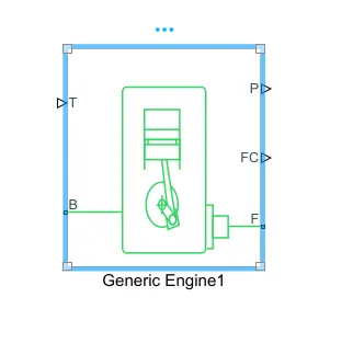
The Generic Engine Block represents a general internal combustion engine.Engine type include spark ignition and diesel.Speed power and speed torque parameters are provided.A Throttle physical signal input specifies the normalized engine torque.A physical signal port outputs engine fuel consumption rate based on choice of fuel consumption model.
The main ports are
- B-Rotational conserving port,representing the engine block
- F-Rotational conserving port,representing engine crankshaft
- T-Physical signal input Port,specifying the normalized engine throttle level
- P-Physical signal output port,representing the instantaneous engine power inW
- FC-Physical Signal output port,reporting fuel consumption rate.
Variable Ratio Transmission Block
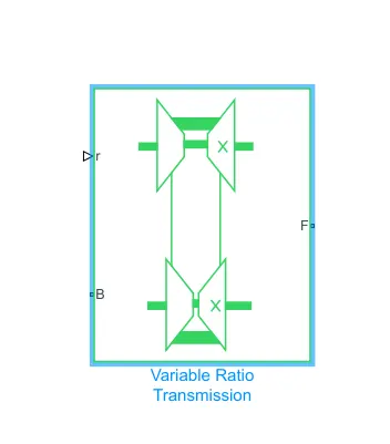
The Variable Ratio Transmission Block represents a gearbox that dynamically transfers motion and torque between the two connected driveshaft axes,base and follower.
Main Ports are:
- B-Base Pulley or Drive Pulley
- F-Follower Pulley or Driven Pulley
- r-Variable transmission ratio
Vehicle Body Block
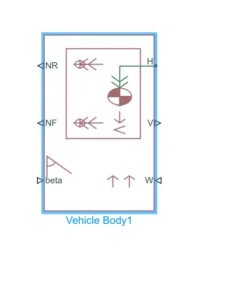
The Vehicle Body Block represents a two axle vehicle body in longitudinal motion.The vehicle can have the same or a different number of wheels on each axle.The vehicle can also have a center of gravity(CG) that is at or below the plane of travel.
The block has anoption to inlude an externally defined mass and an externally defined inertia.The mass,inertia and center of gravity of the vehicle body can vary over the course of simulation in response to system changes.
Input Ports:
1.Beta-Road Incline angle(rad):physical signal input port for road incline angle
2.W-Head Wine Speed(m/s):physical signal input port for road incline angle
3.CG-Center of gravity(m)physical signal input port of externally defined mass relative to the cg of vehicle
Output Ports:
1.NR-Rear Axle Normal Force(N):physical signal output port for the rear axle which is considered as positive acting downward
2.NF-Front axle Normal Force(N):physical signal output port for the Front axle which is considered as positive acting downward
3.V-Longitudinal Velocity (m/s):physical output signal of vehicle velocity
Conserving Ports:
H-Horizontal Motion:Conserving Port related to horizontal motion of vehicle body.
Double Shoe Brake Block
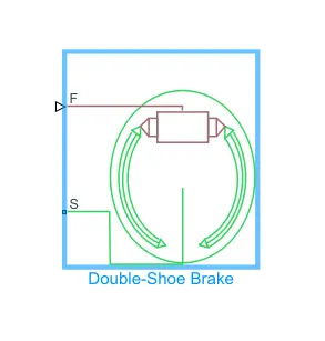
The Double Shoe Brake Block represents a frictional brake with two pivoted rigid shoes that press against a rotating drum to produce a braking action.Double shoe brakes provide high braking torque with small actuator deflections in applications that include motor vehicles and some heavy machinery.
Input Ports
F-Physical signal input port associated with the applied actuating force
Conserving Ports
S-Rotational conserving port associated with the rotating drum shaft
Tire (magic formula) Block
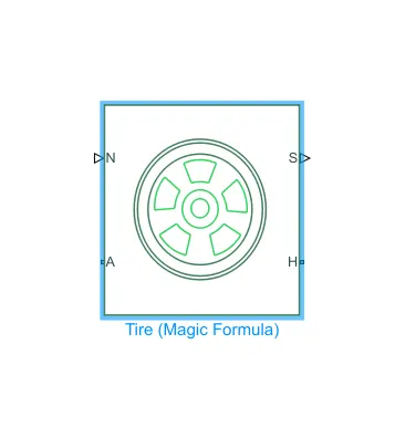
The Tire(magic formula) block models a tire with a longitudinal behavior given by the magic formula,an empirical equation based on four fitting coefficients.The block can model tire dyanamics under constant or variable pavemnet conditions.
The longitudinal direction of the tire is the same as its direction of motion as it rolls on pavement.this block is a structural component based on the tire road interaction block.
BAJA ATV MODEL WITHOUT DASHBOARD(cvtModel)
Main Model:
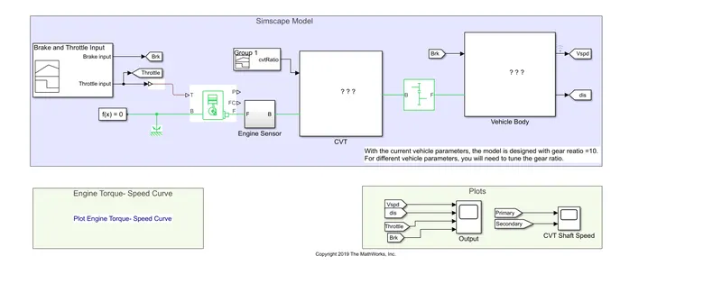
Procedure:
1.The throttle signal is generated by signal builder block and inputted to generic engine.
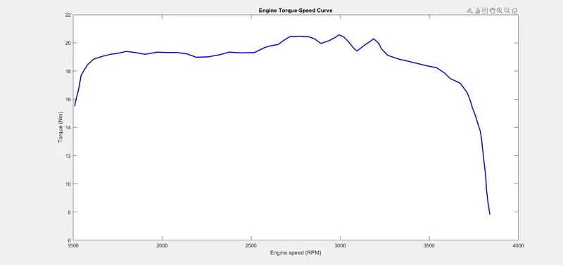
2.The torque and speed vector are inputted from matlab workspace.
3.The engine will generate the output rpm which can be taken from the crankshaft output.this speed will be given to the ideal rotational motion sensor to sense the output rpm
4.Then the output is given to a simple gear to reduce the speed where the gear ratio is '4'.
5.Then the output speed from the gear reducer is given to variable ratio transmission block(CVT).
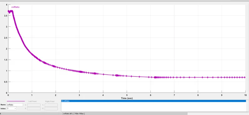
6.Then the CVT ratio is provided to the CVT block through signal builder.
7.The speed is controlled by the variable CVT ratios and the this controlled speed is inputted to vehicle axle.
8.The brake signal is generated by the signal builder and inputted to the vehicle body for applying the brake to axle.
9.The power from the CVT is given to axle and the vehicle accelerates according to the speed and the velocity is taken as output from the vehicle body for further analysis.
Input signals
Throttle Input Signals:

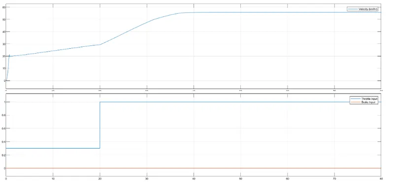
Throttle starts at 0.3 and then moves to 1 at 20th second.
Brake input signal:
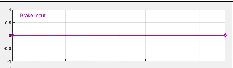
The brake input remains zero.
CVT Ratio input:
SUBSYSTEMS USED IN THE MODEL:
1.Engine Sensor Sub System
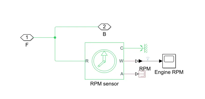
this subsystem measure engine rotational speed as it takes the ouput of the engine.
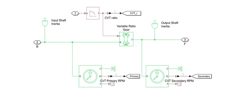
2.CVT Sub System
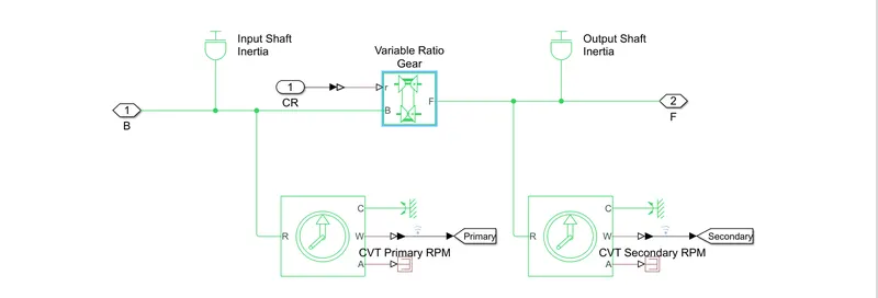
this subsystem provides the input and output shafts of the cvt with inertia and measures the input shaft.
3.Vehicle Body Sub System
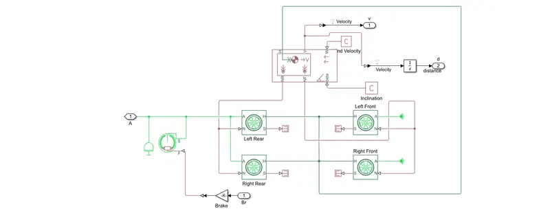
From this subsystem the rear wheel drive is the output from the gearbox is inputted to rear axle and an inertia is added and the shoe brake's conserving port is connected to axle.Then the same axle connects the two rear tyres while the front tyre is free to rotate.
The rear tyres N port is connected together and then connected together and then connected to vehicle body Nr output ports,while the front are connected to the Nf vehicle body output ports.
RESULTS
Torque speed output:
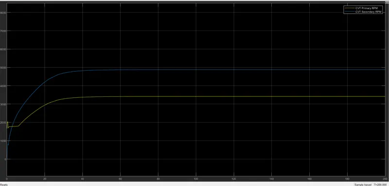
CVT Speed Plot:
BAJA ATV MODEL WITH DASHBOARD(cvtModel_dashboard)
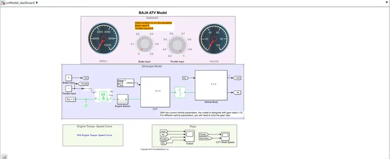
Main Model:
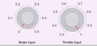
DASHBOARD GIVEN:
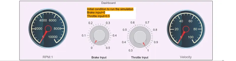
User Controls:
Procedure:
The model workflow process is same as the process of BAJA ATV MODEL WITHOUT DASHBOARD but the throttle and brake inputs are controlled by the user with knobs.
RESULTS
Engine Speed Plot:
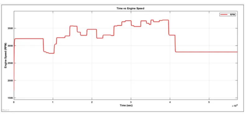
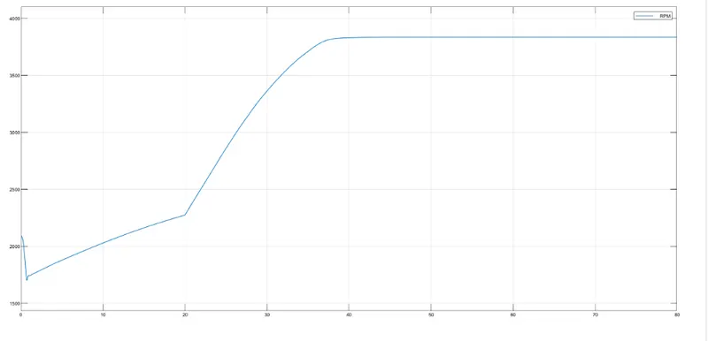
Here the engine speed is generated according to the inputs like throttle,brake,torque and speed vectors.The runtime is not defined so the brake and throttle are controlled by the user.
Engine Speed vs Gear Reduction Speed Plot:
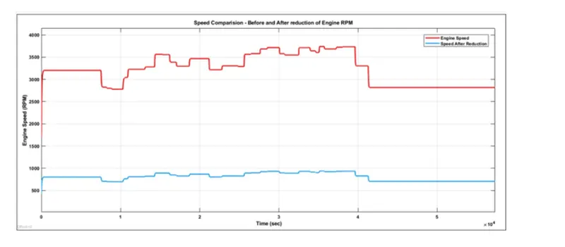
Here the engine speed is reduced by the Gear Ratio 4
Speed Vs Throttle Plot:
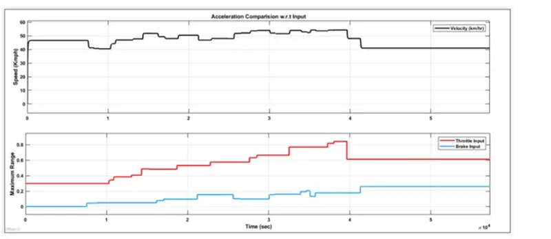
From the graph the vehicle is accelerating while the throttle is applied and decelerated while brake is applied.
BAJA ATV model-Mapped Lookup Table without Dashboard(cvtModel_mapped)
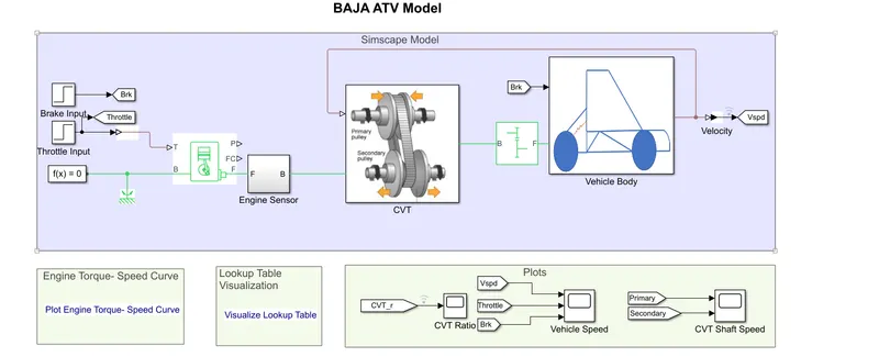
Main Model
Lookup Table:
A Lookup Table is an array of data that maps input values to output values,thereby approximating a mathematical expression.Given a set of input values,a lookup retrieves the corresponding output values from the table.if the lookup table does not explicitly define the input values,simulink can estimate an output values using interpolation,extrapolation or rounding.b
A Lookup table uses an array of data to map input values to output values.
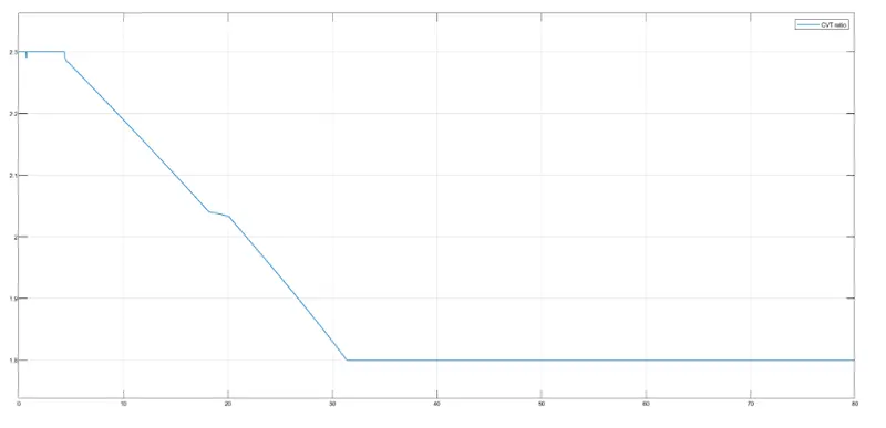
In place of CVT ratio input,a lookup table is assigned in the models below.
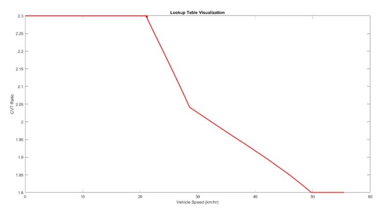
CVT Ratio Vs Vehicle speed
here,
0-20km/hr the CVT ratio is constant at 2.3
20-30km/hr the CVT ratio reduces to 2.03
30-50km/hr the CVT ratio reduces to 1.8
Then From 50km/hr the CVT ratio is constant at 1.8
Using Step block the brake input and throttle input are given.
Output:
Velocity
CVT Ratio
Engine Speed
Conclusion
Simulation of models of BAJA ATV vehicle has been performed and output is plotted.
-----------------------------------------------------------------------------------------------------------------------------------------------------------------------------------------------------------------------------