Week 8 - Challenge 1 - Base Bracket Design
AIM
Create the Base Bracket Plastic component through the given Class-A surface.
REPORT
Given Class A surface :
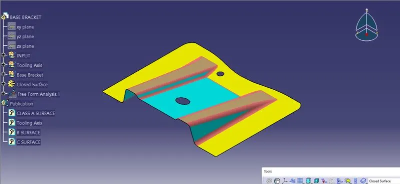
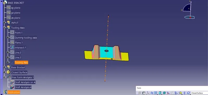
1. Report on Creation of tooling axis
- Using join or boundary commands check the connectivity of the given Class A surface
- Visually inspect the best possible direction for tooling axis. In this case we select Z-axis as our tooling direction.
- We now look for the best position for the tooling axis to pass through. In the Class A surface we can see two holes. We select the bigger hole which is near to the center of the surface for the tooling axis.
- Now using the point command we create a point in the center of the hole.
- Using the line command we create a dummy tooling axis along the z axis direction passing through the point we created earlier
- Now we create a plane with yz plane as the reference at the above point.
- Now we use the intersection command to create an intersection between the class A surface and the newly created plane.
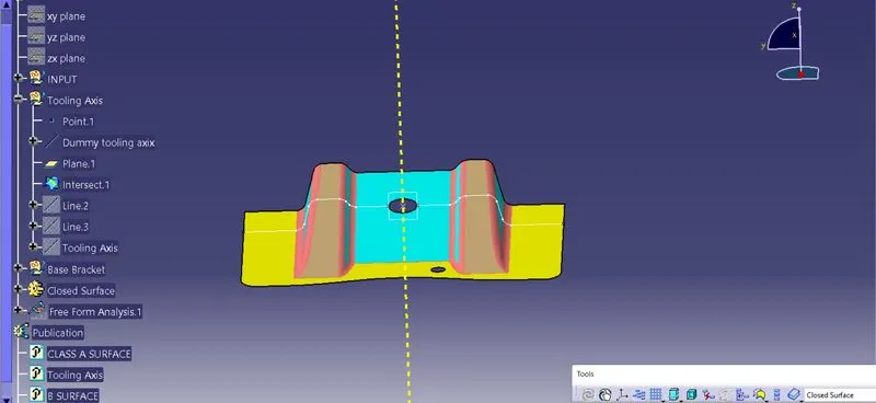
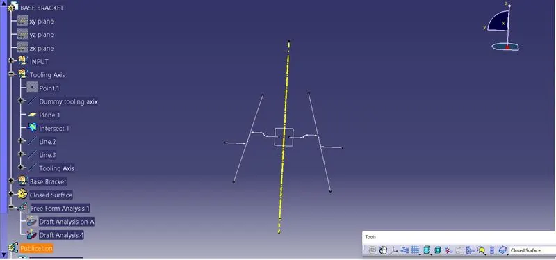
- Now we use the bisecting line method for the creation of tooling axis.
- We draw two lines on two surfaces on their vertices using the line command point to point option.
- Then we again open the line command and click on the bisecting lines option and select the point.
- A new line is formed along z axis which is the new tooling axis.
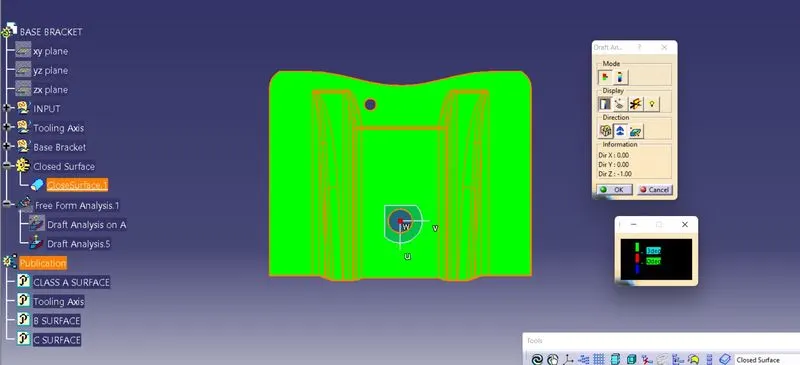
2. Draft Analysis on Class A Surface
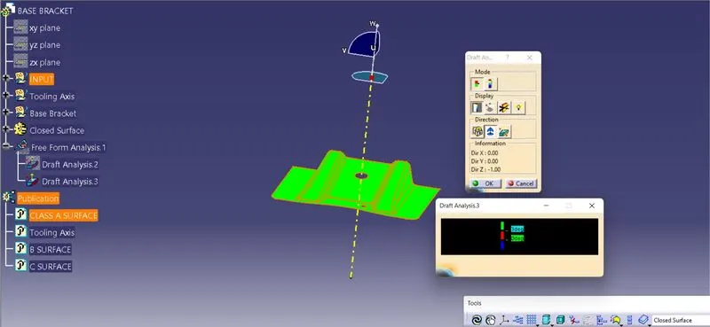
- Select the feature draft analysis option.
- Use the Compass to define the new current draft direction.
- Click on the surface.
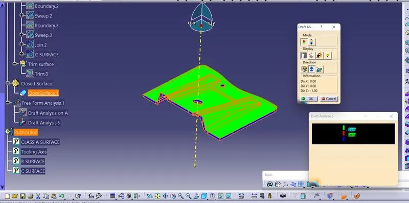
- The draft analysis is displayed wherein green colour shows positive draft.
3. Creating Class B Surface
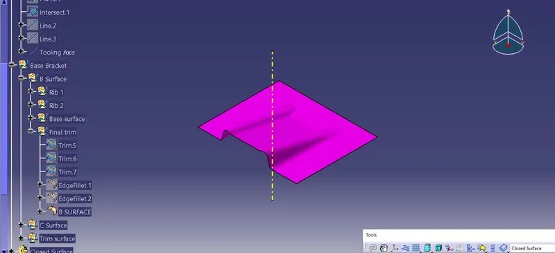
- Firstly extract the right side rib of Class A surface using extract command.
- Then using untrim command untrin all the extracted surfaces.
- Then using the extrapolate command extrapolate the untrimmed surfaces inorder to increase the length.
- Now trim the surfaces to form the required surface.
- Then using Offset command offset the surface to 2.5mm inorder to get the required thickness.
- Similary extract the left side rib and repeat the same steps.
- Now Similarly do the same steps for the slanted as well as the flat surface and offset it to 2.5mm.
- And now trim everything inorder to get the required surface
- Now fillet the surface to required amount, we get the Class B Surface.
4. Creation of Class C Surface
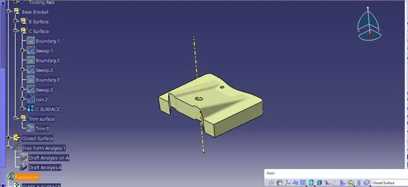
- Use the boundary command to identify and select all of the boundaries of the Class A Surface.
- Use the sweep command. Select the line option. Select 'with draft direction'. Click on the first boundary and select the tooling axis and set the angle to 3 deg. Then finally select the direction.
- Once sweep is applied to all the boundaries click on join option and join them all. Thats your C surface
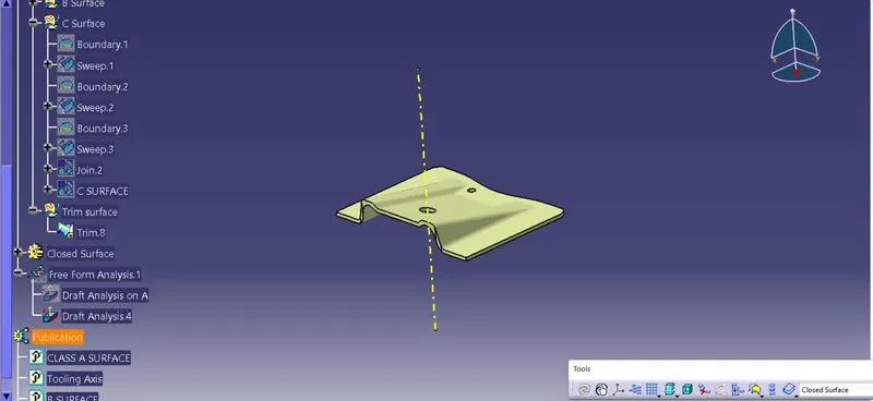
5. Creation of Final Trim
- Once Class B and Class C are created, use the trim command to join them as required.
6. Creation of Closed surface
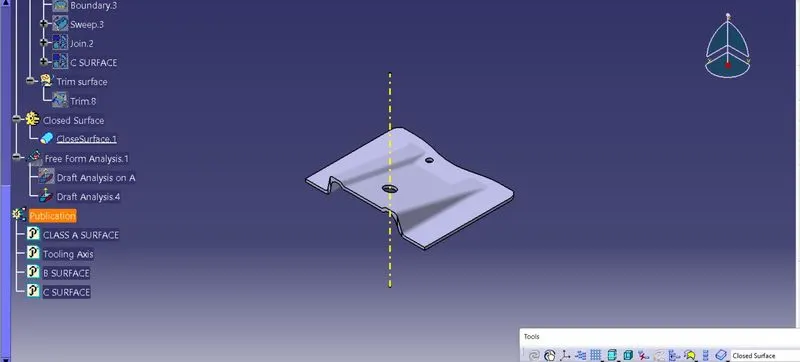
- Once the final trim is created, open the part window and define the work on part body.
- Click on closed surface option and click on the final trim.
- The New body is created.
7. Draft Analysis on Closed surface
- Just as draft analysis was done on A surface, we do draft analysis on the closed surface.
 \
\
RESULTS
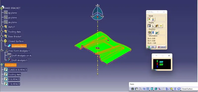
1. Isometric view
2. Front view
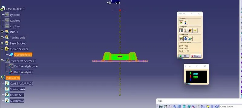
3. Side view
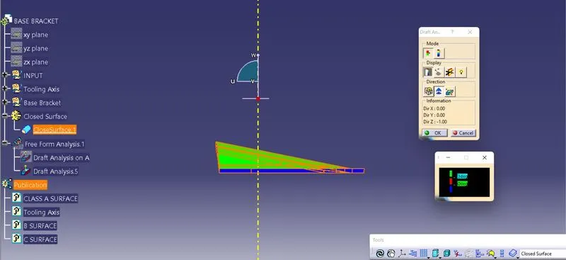
4. Top view