Week 8 - BlockMesh Drill down challenge
THE BLOCKMESH DRILL
Steps :
- Creating a copy of tutorial of blockMesh.
- Then editing the BlockMeshdict file and controldict file along velocity and pressure file.
- Then we use paraFoam to plot the graphs.
- conclusion
Explanation:
- After opening the terminaml we navigate to the tutorial folder by using the tut command.
- Then we navigate to the incompressible folder by cd incompressible .Similalry there is another file called cavity we navigate to it by using the same command with folder name changed accordingly.
- And there will be one more folder called cavity and then we use the following command
- cp -r cavity $FOAM_RUN/test.
- The above command craetes a test folder containing the cavity folder .
- Then if we navigate inside the cavity folder we will find three folders of 0 ,constant and system.
- When we navigate to the system folder we should edit the file blockMeshDict file with
- gedit blockMeshDict and the editing to be done will be shown below.
- also we have to edit the file controlDict file along with p and U file which is found in 0 folder.
- After changing the file we will return to test folder with cd ../
- and run the command blockMesh this is used to create a mesh along with the model.
- Then we run the command icoFoam which is mainly used to run the simulation.Then the simulation starts we have to do it for four different cases.
- Then type the command paraFoam inorder to have a paraview of model.
Solver used in this problem:
We need a solver which solves a incompressible laminar Navier steokes equation (continuity and momentum ),we hence choose icoFoam which is present as an inbuilt directory in openFoam software.
Let us consider creating the geometry using 5 blocks as shown in the figure below,
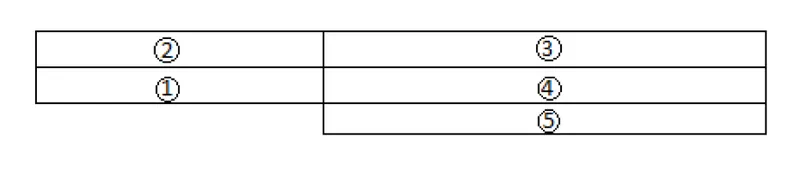
We start the indexing the vertices on the back side of the blocks hence we start with the index from 0.Finally after complete indexing this is how it looks.
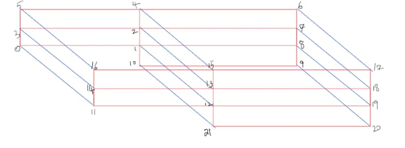
This is how we need to edit the based on the boundry conditions for the top ,bottom,sidewalls,back and front .
After defining the boundaries correctly, to check if you have given defined them correctly, execute the blockMesh command in the terminal.Now open paraFoam, select all the patches and click apply. You will now be able to see the boundary conditions that have been applied to the geometry.The direction chosen is the anticlockwise direction for the flux to move outwards.According to the right hand rule.
/--------------------------------- C++ -----------------------------------\
  =========                 |
  \\      /  F ield         | OpenFOAM: The Open Source CFD Toolbox
   \\    /   O peration     | Website:  https://openfoam.org
    \\  /    A nd           | Version:  8
     \\/     M anipulation  |
\---------------------------------------------------------------------------/
FoamFile
{
    version     2.0;
    format      ascii;
    class       dictionary;
    object      blockMeshDict;
}
// * * * * * * * * * * * * * * * * * * * * * * * * * * * * * * * * * * * * * //

convertToMeters 1;

vertices
(
    (0 0 0)
    (0.08 0 0 )
    (0.08 0.005 0)
    (0 0.005 0)
    (0.08 0.01 0)
    (0 0.01 0)
    (0.2 0.01 0)
    (0.2 0.005 0)
    (0.2 0 0)
    (0.2 -0.01 0 )
     (0.08 -0.01 0)

    (0 0 0.001)
    (0.08 0 0.001)
    (0.08 0.005 0.001)
    (0 0.005 0.001)
    (0.08 0.01 0.001)
    (0 0.01 0.001)
     (0.2 0.01 0.001)
     (0.2 0.005 0.001)
    (0.2 0 0.001)
     (0.2 -0.01 0.001)
     (0.08 -0.01 0.001)


);

blocks
(
    hex (0 1 2 3 11 12 13 14) (200  10  1) simpleGrading (0.5 1.5 1.0 )
    hex (3 2 4 5 14 13 15 16) (200  10  1) simpleGrading (0.5 0.5 1.0 )
    hex (2 7 6 4 13 18 17 15) (200  10  1) simpleGrading (1.5 0.5 1.0)
    hex (1 8 7 2 12 19 18 13) (200  10  1) simpleGrading (1.5 1.5 1.0 )
    hex (10 9 8 1 21 20 19 12) (200 10 1) simpleGrading (1.5 1.5 1.0)
);

edges
(
);

boundary
(

   inlet
       {
           type patch;
           faces
                (
                   (0 11 14 3)
                   (3 14 16 5)
 );
       }
  outlet
       {
           type patch;
           faces
           (
                (20 9 8 19)
                (19 8 7 18)
                (18 7 6 17)
            );
        }
   front
       {
           type empty;
           faces
            (

            (11 12 13 14)
            (14 13 15 16)
            (13 18 17 15)
             (12 19 18 13)
            (21 20 19 12)


);

}

  Back
      {
           type empty;
           faces
            (
            (3 2 1 0)
            (5 4 2 3 )
            (4 6 7 2)
            (2 7 8 1 )
            (1 8 9 10)


);

}


       Bottom
           {
             type wall;
                faces
                 (
                       (0 1 12 11)
                       (10 9 20 21)
                 );
             }


       Top
           {
             type wall;
                faces
                 (
                    (4 5 16 15)
                    (6 4 15 17)

                 );
             }


       Stepside
           {
             type wall;
                faces
                 (
                        (1 10 21 12)
                 );
             }


    );


mergePatchPairs
(
);

// ************************* //A)Boundry conditions obtained:
This is the section for boundry condtion which we had defined in the file.The mesh for the profile can be shown as follows.
B)Initial condtions:
We define the initial conditions for the simulation by editing the files in 0 folder which actaually stores the data in time t=0 .
The initial condtions for simulation are pressure and velocity.
THE PRESSURE FILE
/--------------------------------- C++ -----------------------------------\
  =========                 |
  \\      /  F ield         | OpenFOAM: The Open Source CFD Toolbox
   \\    /   O peration     | Website:  https://openfoam.org
    \\  /    A nd           | Version:  8
     \\/     M anipulation  |
\---------------------------------------------------------------------------/
FoamFile
{
    version     2.0;
    format      ascii;
    class       volScalarField;
    object      p;
}
// * * * * * * * * * * * * * * * * * * * * * * * * * * * * * * * * * * * * * //

dimensions      [0 2.0 -2.0 0 0 0 0];

internalField   uniform 0;

boundaryField
{
    inlet
    {
        type            zeroGradient;
    }

    outlet
    {
        type            fixedValue;
        value            uniform 0;
    }

    front
    {
        type            empty;
    }

     Back
    {
        type            empty;
    }


    Top
    {
     type             zeroGradient;
    }

 Bottom
    {
     type             zeroGradient;
    }

 Stepside
    {
     type             zeroGradient;
    }

}

// ************************* //
THE VELOCITY FILE
/--------------------------------- C++ -----------------------------------\
  =========                 |
  \\      /  F ield         | OpenFOAM: The Open Source CFD Toolbox
   \\    /   O peration     | Website:  https://openfoam.org
    \\  /    A nd           | Version:  8
     \\/     M anipulation  |
\---------------------------------------------------------------------------/
FoamFile
{
    version     2.0;
    format      ascii;
    class       volVectorField;
    object      U;
}
// * * * * * * * * * * * * * * * * * * * * * * * * * * * * * * * * * * * * * //

dimensions      [0 1.0 -1.0 0 0 0 0];

internalField   uniform (0 0 0);

boundaryField
{
    inlet
    {
        type            fixedValue;
        value           uniform (1.0 0 0);
    }

    outlet
    {
        type            zeroGradient;
    }
    Top
     {
        type             noSlip;
     }
     Back
    {
        type            empty;
    }

 Bottom
     {
        type             noSlip;
     }
    front
    {
        type            empty;
    }

   Bottom
    {
        type            noSlip;
    }
     Stepside
    {
        type            noSlip;
    }


}

// ************************* //
And finally the controldict file which looks after the simulation process.based on time duration etc.
THE CONTROLDICT FILE
=========                 |
  \\      /  F ield         | OpenFOAM: The Open Source CFD Toolbox
   \\    /   O peration     | Website:  https://openfoam.org
    \\  /    A nd           | Version:  8
     \\/     M anipulation  |
\---------------------------------------------------------------------------/
FoamFile
{
    version     2.0;
    format      ascii;
    class       dictionary;
    location    "system";
    object      controlDict;
}
// * * * * * * * * * * * * * * * * * * * * * * * * * * * * * * * * * * * * * //

application     icoFoam;

startFrom       startTime;

startTime       0;

stopAt          endTime;

endTime         1;

deltaT          0.0001;

writeControl    timeStep;

writeInterval   1000;

purgeWrite      0;

writeFormat     ascii;

writePrecision  6;

writeCompression off;

timeFormat      general;

timePrecision   6;

runTimeModifiable true;


// ************************* //
Now we comapre the various Grading schemes
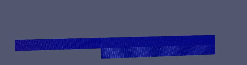
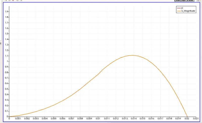
1) Velocity profile for Grading scheme 1:
For grading scheme 1 we have to make changes in blocks part in blockMeshDict as this

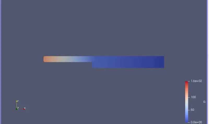
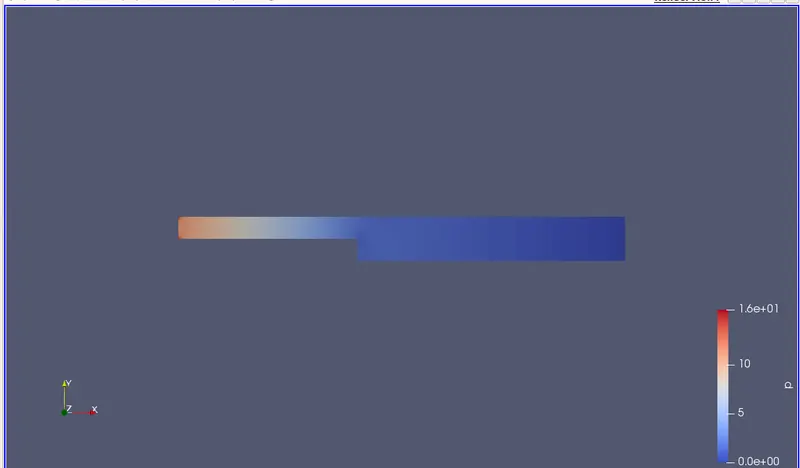
Pressure Profile
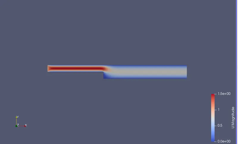
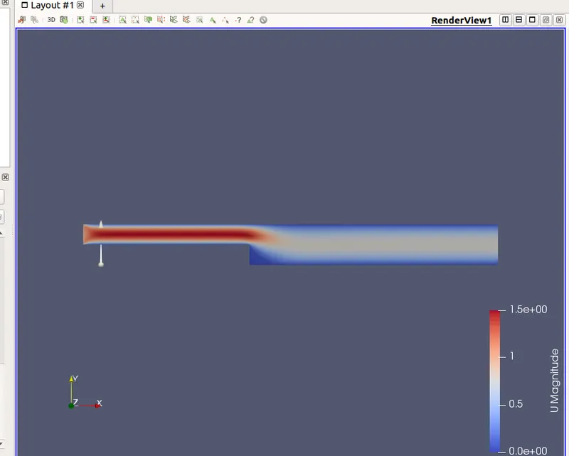
Velocity contour
Mesh
Velocity plot
2)Velocity profile for Grading scheme 0.2
For grading scheme 0.2 we have to make changes in blocks part in blockMeshDict as this

Velocity contour
Pressure contour
Mesh
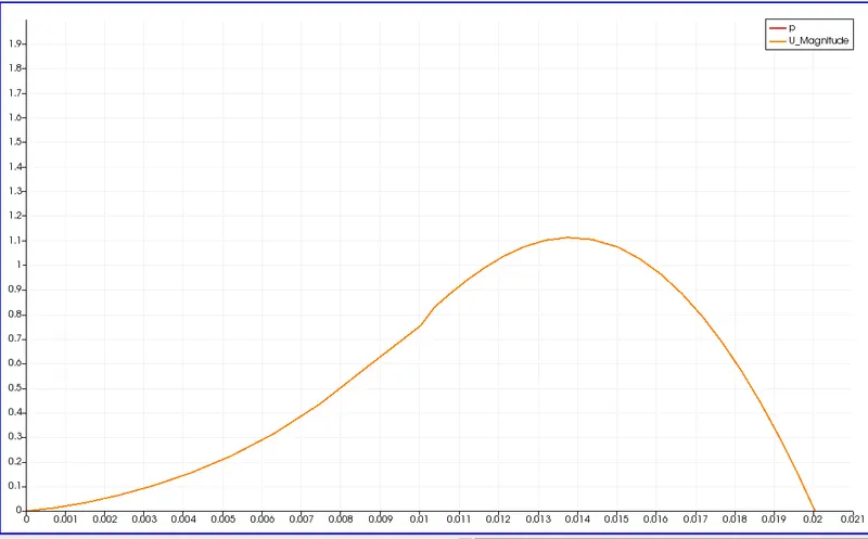
Velocity plot
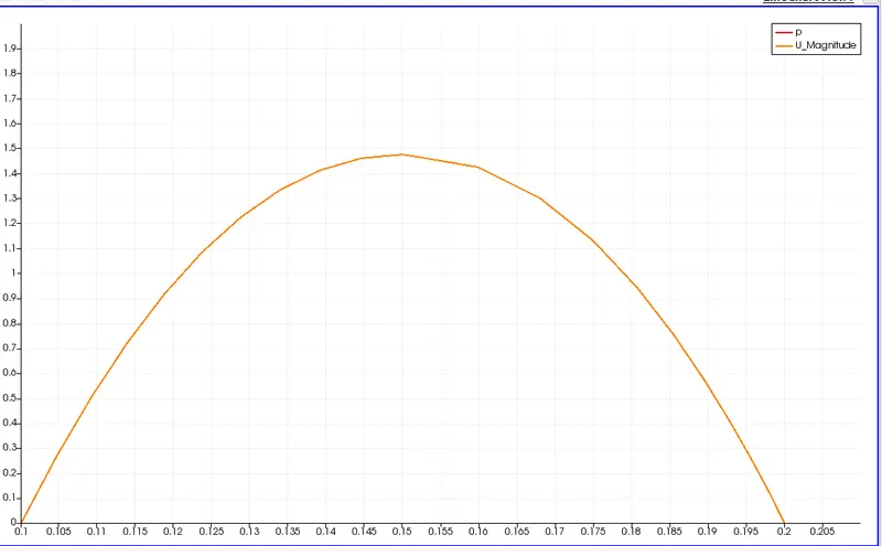
3)Profile for Grading scheme 0.5
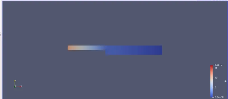
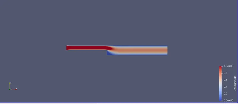
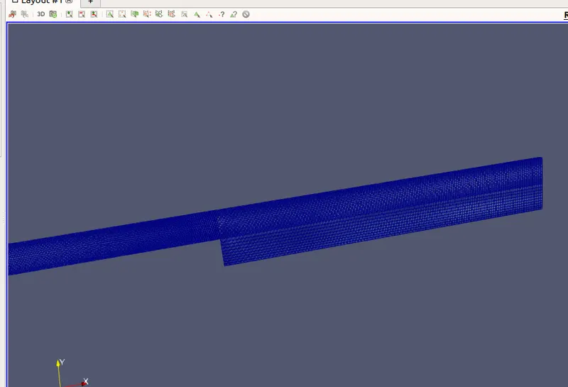
For grading scheme 0.5 we have to make changes in blocks part in blockMeshDict as this

Pressure contour
Velocity contour
Mesh
Velocity plot
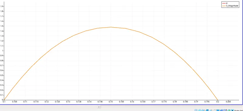
3)Grading scheme of 0.8
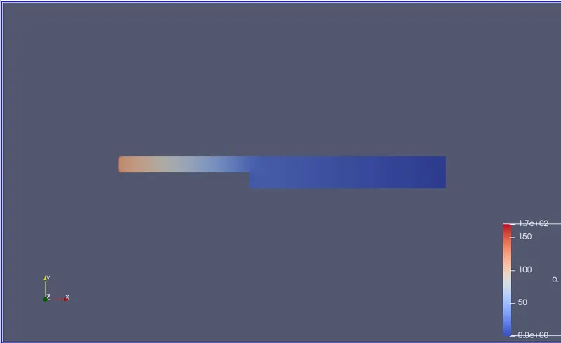
For grading scheme 0.8 we have to make changes in blocks part in blockMeshDict as this

Pressure contour
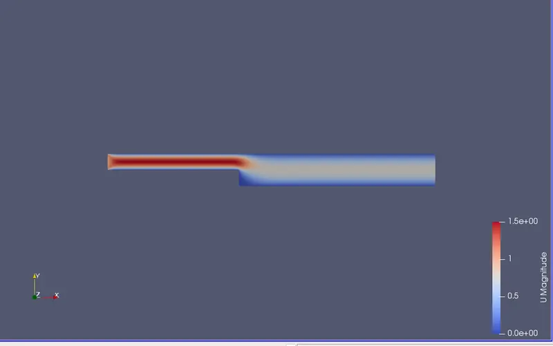
Velocity contour
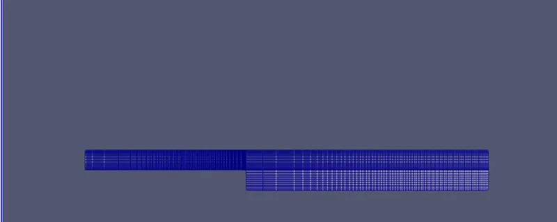
Mesh
Velocity plot
Importance of Grading Factor:
- It specifies the maximum ratio of adjacent mesh edges of transitioning between coarse of finer regions.
- If the grading factor is less it produces a fine mesh.
- Actually, the grading factor in blockMesh is defined as the ratio of the last to first cell size, which is much better behaved that defining the number of cells and the geometric expansion ratio
Conclusion:
As the area of the cross section decreases thr velocity increases since the mass flow rate remains constant.The simulation is being conducted successfully.