Week 8 - BlockMesh Drill down challenge
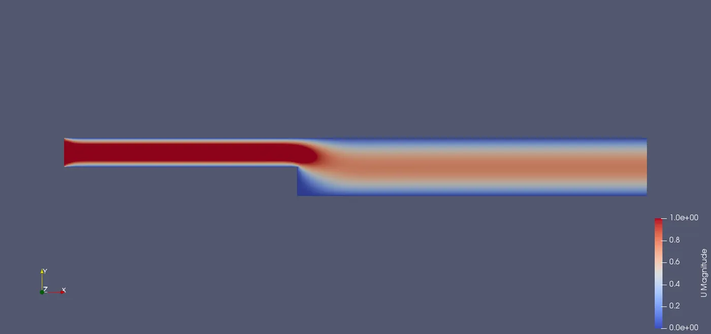
Problem Statement: Create a model as shown in the figure and mesh with the different mesh grading as specified in the problem and measure the velocity at 0.085m from the inlet of the geometry.
Plot the velocity against the length of the block using a line plot.
Given Model:
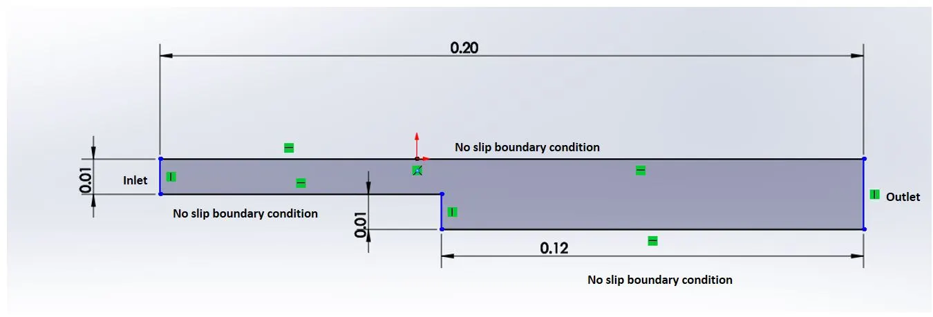
The given dimensions are in meters.
Compare the magnitude of velocity for different grading factors at 0.085m from inlet geometry. Grading Factor (0.2,0.5,0.8)
Mesh Specifications:
- Number of cells along the x direction (longer dimension) = 200
- Number of cells along with the y-direction = 10
- Use a graded mesh. The grading factor near all walls should be 0.2
Boundary Conditions:
The model is divided into 5 blocks as shown in the figure:
Boundary conditions are defined for inlet, outlet, fixed wall, and no-slip wall.
For inlet and Outlet:
Type is Patch because this is a generic type containing no geometrical or topological information about the mesh.
Type empty because no solutions are generated in the front and back faces since the model is considered 2D flow.
No-Slip walls:
Type is wall because the inlet patches and outlet patches coincide with a solid wall of the model which requires physical modeling that is boundary layer formation at these walls.
BlockMeshDict with a simple grading 1
/*--------------------------------*- C++ -*----------------------------------*
  =========                 |
  \      /  F ield         | OpenFOAM: The Open Source CFD Toolbox
   \    /   O peration     | Website:  https://openfoam.org
    \  /    A nd           | Version:  8
     \/     M anipulation  |
*---------------------------------------------------------------------------*/
FoamFile
{
    version     2.0;
    format      ascii;
    class       dictionary;
    object      blockMeshDict;
}
// * * * * * * * * * * * * * * * * * * * * * * * * * * * * * * * * * * * * * //

convertToMeters 1;

vertices
(
    (0 0 0)		// v0
    (0.08 0 0)		// v1
    (0.08 0.005 0)	// v2
    (0 0.005 0)	// v3
    (0.08 0.01 0)	//v4
    (0 0.01 0)		//v5
    (0.2 0.01 0)	//v6
    (0.2 0.005 0)	//v7
    (0.2 0 0) 		//v8
    (0.2 -0.01 0)	//v9
    (0.08 -0.01 0)	//v10
    (0 0 0.01)		// v11
    (0.08 0 0.01)	// v12
    (0.08 0.005 0.01)	// v13
    (0 0.005 0.01)	// v14
    (0.08 0.01 0.01)	//v15
    (0 0.01 0.01)	//v16
    (0.2 0.01 0.01)	//v17
    (0.2 0.005 0.01)	//v18
    (0.2 0 0.01)	//v19
    (0.2 -0.01 0.01)	//v20
    (0.08 -0.01 0.01)	//v21
);

blocks
(
    hex (0 1 2 3 11 12 13 14) (80 10 1) simpleGrading (1 1 1)
    hex (3 2 4 5 14 13 15 16) (80 10 1) simpleGrading (1 1 1)
    hex (10 9 8 1 21 20 19 12) (120 20 1) simpleGrading (1 1 1)
    hex (1 8 7 2 12 19 18 13) (120 10 1) simpleGrading (1 1 1)
    hex (2 7 6 4 13 18 17 15) (120 10 1) simpleGrading (1 1 1)

);

edges
(
);

boundary
(
   inlet
    {
        type patch;
        faces
        (
            (0 11 14 3)
            (3 14 16 5)
        );
    }
   outlet
    {
        type patch;
        faces
        (
            (9 8 19 20)
            (8 7 18 19)
            (7 6 17 18)
        );
    }
    NoSlipWalls
    {
        type wall;
        faces
        (
            (5 16 15 4)
            (4 15 17 6)
            (1 10 21 12)
            (0 1 12 11)
            (10 9 20 21)

        );
    }
    frontAndBack
    {
        type empty;
        faces
        (
            (11 12 13 14)
            (14 13 15 16)
            (21 20 19 12)
            (12 19 18 13)
            (13 18 17 15)
            (0 3 2 1)
            (3 5 4 2)
            (10 1 8 9)
            (1 2 7 8)
            (2 4 6 7)
        );
    }
);

mergePatchPairs
(
);

// ************************************************************************* //
Explanation:
In the above code, the first seven lines contain the header information and the code information is in foam file which is enclosed in '{}'.
After the file information, the dimensions are converted into meters by multiplying the scaling factor by 1.
Then vertices for each block is defined using the Right-hand thumb rule in which the z-axis is pointing outwards.
Blocks are defined after the definition of vertices for the blocks where the hex is defining the shape of the block which is hexahedra. The order of the vertices in defining the block should be done carefully because this line also specifies a local axis for the vertices to which the number of cells is defined along with grading. Here simple grading is cell expansion. In the parenthesis, we specify the ratio which is the width of the end cell along one edge of a block to the width of the start cell along that edge.
Since there are no curved edges in the geometry it is left empty i.e., no points are specified within the parenthesis.
Boundary Conditions:
For the inlet and outlet, the type of boundary conditions specified are:
type: patch type on which particular boundary conditions are applied and faces: mean a list of block faces that make up the patch.
NoSlipWalls is of wall type since particular physical properties are defined at these walls.
Front and Back walls are of type empty because there is no solution required since the flow considered is 2D flow.
Initial conditions
Initial Conditions for Pressure:
/*--------------------------------*- C++ -*----------------------------------*
  =========                 |
  \      /  F ield         | OpenFOAM: The Open Source CFD Toolbox
   \    /   O peration     | Website:  https://openfoam.org
    \  /    A nd           | Version:  8
     \/     M anipulation  |
*---------------------------------------------------------------------------*/
FoamFile
{
    version     2.0;
    format      ascii;
    class       volScalarField;
    object      p;
}
// * * * * * * * * * * * * * * * * * * * * * * * * * * * * * * * * * * * * * //

dimensions      [0 2 -2 0 0 0 0];

internalField   uniform 0;

boundaryField
{
    inlet
    {
        type            zeroGradient;
    }

    outlet
    {
         type            fixedValue;
        value           uniform 0;
    }

    NoSlipWalls
    {
        type            zeroGradient;
    }

    frontAndBack
    {
        type            empty;
    }
}

// ************************************************************************* //
Explanation:
In the above code, the first 7 lines represent the header information and the next nine-lines contain file information for which heading is Foam file.
The dimension line gives in the dimensions of the physical quantity to which the boundary conditions are applied. Here it is kinematic pressure i.e., `m^2s^-2`
Internal field species the value of the internal field in which a single value is assigned to all elements within the field.
Then Initial Conditions are specified
The type of boundary conditions considered is Velocity inlet and outflow boundary conditions since the flow is incompressible.
Hence for the inlet, the pressure is zero gradients which means the normal gradient of P is zero. This is used when the fluid flows outside the domain at a patch face and a fixed value is used when the fluid flows into the domain. Zero-gradient is used for the flows which are fully developed i.e., the flow remains constant as time progresses.
Since no-slip walls are connected to the patch at which physical condition is defined it is specified as zero gradients and for front and back since no solution is required the type is empty.
Initial Conditions for Velocity:
/*--------------------------------*- C++ -*----------------------------------*
  =========                 |
  \      /  F ield         | OpenFOAM: The Open Source CFD Toolbox
   \    /   O peration     | Website:  https://openfoam.org
    \  /    A nd           | Version:  8
     \/     M anipulation  |
*---------------------------------------------------------------------------*/
FoamFile
{
    version     2.0;
    format      ascii;
    class       volVectorField;
    object      U;
}
// * * * * * * * * * * * * * * * * * * * * * * * * * * * * * * * * * * * * * //

dimensions      [0 1 -1 0 0 0 0];

internalField   uniform (0 0 0);

boundaryField
{
    inlet
    {
        type            fixedValue;
        value           uniform (1 0 0);
    }
    outlet
    {
        type            zeroGradient;
    }

    NoSlipWalls
    {
        type            noSlip;
    }

    frontAndBack
    {
        type            empty;
    }
}

// ************************************************************************* //
Explanation:
The unit for the velocity is m/s which is specified in the dimensions as [0 1 -1 0 0 0 0]
Internal points in the model are specified as 0.
In the velocity boundary conditions since there is an initial velocity a fixed value of 1 is defined at the inlet.
At the outlet, the velocity is specified as zero-gradient since the flow attains the steady-state when it reaches the outlet of the model.
No-slip is specified at the fixed wall because of the boundary layer. noSlip fixes the values of the velocity to zero at the walls.
Physical Property:
/*--------------------------------*- C++ -*----------------------------------*
  =========                 |
  \      /  F ield         | OpenFOAM: The Open Source CFD Toolbox
   \    /   O peration     | Website:  https://openfoam.org
    \  /    A nd           | Version:  8
     \/     M anipulation  |
*---------------------------------------------------------------------------*/
FoamFile
{
    version     2.0;
    format      ascii;
    class       dictionary;
    location    "constant";
    object      transportProperties;
}
// * * * * * * * * * * * * * * * * * * * * * * * * * * * * * * * * * * * * * //

nu              [0 2 -1 0 0 0 0] 0.01;


// ************************************************************************* //
The only physical property for the solver icoFoam is kinematic viscosity which is stored in the transport properties in the constant directory.
For this case, the initial Reynolds number is taken as 10, for which the formula is defined as `Re = (d*U)/nu`
where d and U are the characteristic lengths and velocity respectively and `nu` is kinematic viscosity. Here d =0.1m, U = 1m/s when computed results in 0.01 `m^2s^-2` .
Controls:
/*--------------------------------*- C++ -*----------------------------------*
  =========                 |
  \      /  F ield         | OpenFOAM: The Open Source CFD Toolbox
   \    /   O peration     | Website:  https://openfoam.org
    \  /    A nd           | Version:  8
     \/     M anipulation  |
*---------------------------------------------------------------------------*/
FoamFile
{
    version     2.0;
    format      ascii;
    class       dictionary;
    location    "system";
    object      controlDict;
}
// * * * * * * * * * * * * * * * * * * * * * * * * * * * * * * * * * * * * * //

application     icoFoam;

startFrom       startTime;

startTime       0;

stopAt          endTime;

endTime         0.1;

deltaT          0.000025;

writeControl    timeStep;

writeInterval   20;

purgeWrite      0;

writeFormat     ascii;

writePrecision  6;

writeCompression off;

timeFormat      general;

timePrecision   6;

runTimeModifiable true;


// ************************************************************************* //
This code contains the start time, end time, time step size which can be read from the controlDict dictionary in the system directory.
Start time starts from 0 which means that OpenFoam needs to read field data from a directory named 0. For the end time as a general rule, the flow should pass through the domain 10 times to reach a steady-state in laminar flow hence 0.1 seconds.
The next step is to define the time step size which can be calculated from the courant number formula `C= (trianglet*U)/(trianglex)`. where C =1, U =1 m/s,
`trianglex = d/n`
where d is the length of the model and n is no. of cells the model is divided into in x-direction.
`trianglex = 0.0001`
`trianglet` = 0.0001 which when used resulted in the error due to an increase in courant number hence the time step size is decreased further to obtain a stable solution.
The `trianglet` obtained is done for simple grading 1. With the change in grading factor`trianglex` changes which in turn changes the courant number.
Write interval 20 in the code specifies the program to store the values after 20-time step iterations.
Steps in the execution of the problem:
1. Choosing the required solver from the tutorial directory. In this case, the given problem is incompressible transient laminar flow hence icoFoam solver is used.
2. Cavity model is used as it is simple and easy to modify.
3. Copy the cavity directory to the Foam run directory because no changes have to be made in the tutorial directories.
4. Inside the run folder the navigate to the cavity directory and to the system directory to modify the BlockmeshDict with the changes mentioned above and similarly navigate to controlDict to make necessary changes..
5. Apply initial conditions by navigating to the 0 directory and then use the gedit command to edit the Pressure and velocity initial conditions.
6. Once the grading is applied the mesh has to be updated using blockMesh. This command is repeated each time the grading is changed.
7. After execution of blockMesh command if there is no error then the solver is executed with icoFoam command.
8. After successful execution the post-processing is done using the paraFoam command which opens the ParaView window
9. In the ParaView window the flow is analyzed for each flow variable.
BlockMesh Dict for simple grading 0.2
/*--------------------------------*- C++ -*----------------------------------*
  =========                 |
  \      /  F ield         | OpenFOAM: The Open Source CFD Toolbox
   \    /   O peration     | Website:  https://openfoam.org
    \  /    A nd           | Version:  8
     \/     M anipulation  |
*---------------------------------------------------------------------------*/
FoamFile
{
    version     2.0;
    format      ascii;
    class       dictionary;
    object      blockMeshDict;
}
// * * * * * * * * * * * * * * * * * * * * * * * * * * * * * * * * * * * * * //

convertToMeters 1;

vertices
(
    (0 0 0)		// v0
    (0.08 0 0)		// v1
    (0.08 0.005 0)	// v2
    (0 0.005 0)	// v3
    (0.08 0.01 0)	//v4
    (0 0.01 0)		//v5
    (0.2 0.01 0)	//v6
    (0.2 0.005 0)	//v7
    (0.2 0 0) 		//v8
    (0.2 -0.01 0)	//v9
    (0.08 -0.01 0)	//v10
    (0 0 0.01)		// v11
    (0.08 0 0.01)	// v12
    (0.08 0.005 0.01)	// v13
    (0 0.005 0.01)	// v14
    (0.08 0.01 0.01)	//v15
    (0 0.01 0.01)	//v16
    (0.2 0.01 0.01)	//v17
    (0.2 0.005 0.01)	//v18
    (0.2 0 0.01)	//v19
    (0.2 -0.01 0.01)	//v20
    (0.08 -0.01 0.01)	//v21
);

blocks
(
    hex (0 1 2 3 11 12 13 14) (80 10 1) simpleGrading (1 5 1)
    hex (3 2 4 5 14 13 15 16) (80 10 1) simpleGrading (1 0.2 1)
    hex (10 9 8 1 21 20 19 12) (120 20 1) simpleGrading (5 5 1)
    hex (1 8 7 2 12 19 18 13) (120 10 1) simpleGrading (5 5 1)
    hex (2 7 6 4 13 18 17 15) (120 10 1) simpleGrading (5 0.2 1)

);

edges
(
);

boundary
(
   inlet
    {
        type patch;
        faces
        (
            (0 11 14 3)
            (3 14 16 5)
        );
    }
   outlet
    {
        type patch;
        faces
        (
            (9 8 19 20)
            (8 7 18 19)
            (7 6 17 18)
        );
    }
    NoSlipWalls
    {
        type wall;
        faces
        (
            (5 16 15 4)
            (4 15 17 6)
            (1 10 21 12)
            (0 1 12 11)
            (10 9 20 21)

        );
    }
    frontAndBack
    {
        type empty;
        faces
        (
            (11 12 13 14)
            (14 13 15 16)
            (21 20 19 12)
            (12 19 18 13)
            (13 18 17 15)
            (0 3 2 1)
            (3 5 4 2)
            (10 1 8 9)
            (1 2 7 8)
            (2 4 6 7)
        );
    }
);

mergePatchPairs
(
);

// ************************************************************************* //
In the above code, the cell grading is changed with 0.2 as grading which means the size of the last cell is 0.2 times the size of the first cell.
BlockMeshDict for simple grading 0.5
/*--------------------------------*- C++ -*----------------------------------*
  =========                 |
  \      /  F ield         | OpenFOAM: The Open Source CFD Toolbox
   \    /   O peration     | Website:  https://openfoam.org
    \  /    A nd           | Version:  8
     \/     M anipulation  |
*---------------------------------------------------------------------------*/
FoamFile
{
    version     2.0;
    format      ascii;
    class       dictionary;
    object      blockMeshDict;
}
// * * * * * * * * * * * * * * * * * * * * * * * * * * * * * * * * * * * * * //

convertToMeters 1;

vertices
(
    (0 0 0)		// v0
    (0.08 0 0)		// v1
    (0.08 0.005 0)	// v2
    (0 0.005 0)	// v3
    (0.08 0.01 0)	//v4
    (0 0.01 0)		//v5
    (0.2 0.01 0)	//v6
    (0.2 0.005 0)	//v7
    (0.2 0 0) 		//v8
    (0.2 -0.01 0)	//v9
    (0.08 -0.01 0)	//v10
    (0 0 0.01)		// v11
    (0.08 0 0.01)	// v12
    (0.08 0.005 0.01)	// v13
    (0 0.005 0.01)	// v14
    (0.08 0.01 0.01)	//v15
    (0 0.01 0.01)	//v16
    (0.2 0.01 0.01)	//v17
    (0.2 0.005 0.01)	//v18
    (0.2 0 0.01)	//v19
    (0.2 -0.01 0.01)	//v20
    (0.08 -0.01 0.01)	//v21
);

blocks
(
    hex (0 1 2 3 11 12 13 14) (80 10 1) simpleGrading (1 2 1)
    hex (3 2 4 5 14 13 15 16) (80 10 1) simpleGrading (1 0.5 1)
    hex (10 9 8 1 21 20 19 12) (120 20 1) simpleGrading (2 2 1)
    hex (1 8 7 2 12 19 18 13) (120 10 1) simpleGrading (2 2 1)
    hex (2 7 6 4 13 18 17 15) (120 10 1) simpleGrading (2 0.5 1)

);

edges
(
);

boundary
(
   inlet
    {
        type patch;
        faces
        (
            (0 11 14 3)
            (3 14 16 5)
        );
    }
   outlet
    {
        type patch;
        faces
        (
            (9 8 19 20)
            (8 7 18 19)
            (7 6 17 18)
        );
    }
    NoSlipWalls
    {
        type wall;
        faces
        (
            (5 16 15 4)
            (4 15 17 6)
            (1 10 21 12)
            (0 1 12 11)
            (10 9 20 21)

        );
    }
    frontAndBack
    {
        type empty;
        faces
        (
            (11 12 13 14)
            (14 13 15 16)
            (21 20 19 12)
            (12 19 18 13)
            (13 18 17 15)
            (0 3 2 1)
            (3 5 4 2)
            (10 1 8 9)
            (1 2 7 8)
            (2 4 6 7)
        );
    }
);

mergePatchPairs
(
);

// ************************************************************************* //
In the above code, the cell grading is changed with 0.5 as grading which means the size of the last cell is 0.2 times the size of the first cell.
BlockMeshDict for simple grading 0.8
/*--------------------------------*- C++ -*----------------------------------*
  =========                 |
  \      /  F ield         | OpenFOAM: The Open Source CFD Toolbox
   \    /   O peration     | Website:  https://openfoam.org
    \  /    A nd           | Version:  8
     \/     M anipulation  |
*---------------------------------------------------------------------------*/
FoamFile
{
    version     2.0;
    format      ascii;
    class       dictionary;
    object      blockMeshDict;
}
// * * * * * * * * * * * * * * * * * * * * * * * * * * * * * * * * * * * * * //

convertToMeters 1;

vertices
(
    (0 0 0)		// v0
    (0.08 0 0)		// v1
    (0.08 0.005 0)	// v2
    (0 0.005 0)	// v3
    (0.08 0.01 0)	//v4
    (0 0.01 0)		//v5
    (0.2 0.01 0)	//v6
    (0.2 0.005 0)	//v7
    (0.2 0 0) 		//v8
    (0.2 -0.01 0)	//v9
    (0.08 -0.01 0)	//v10
    (0 0 0.01)		// v11
    (0.08 0 0.01)	// v12
    (0.08 0.005 0.01)	// v13
    (0 0.005 0.01)	// v14
    (0.08 0.01 0.01)	//v15
    (0 0.01 0.01)	//v16
    (0.2 0.01 0.01)	//v17
    (0.2 0.005 0.01)	//v18
    (0.2 0 0.01)	//v19
    (0.2 -0.01 0.01)	//v20
    (0.08 -0.01 0.01)	//v21
);

blocks
(
    hex (0 1 2 3 11 12 13 14) (80 10 1) simpleGrading (1 1.25 1)
    hex (3 2 4 5 14 13 15 16) (80 10 1) simpleGrading (1 0.8 1)
    hex (10 9 8 1 21 20 19 12) (120 20 1) simpleGrading (1.25 1.25 1)
    hex (1 8 7 2 12 19 18 13) (120 10 1) simpleGrading (1.25 1.25 1)
    hex (2 7 6 4 13 18 17 15) (120 10 1) simpleGrading (1.25 0.5 1)

);

edges
(
);

boundary
(
   inlet
    {
        type patch;
        faces
        (
            (0 11 14 3)
            (3 14 16 5)
        );
    }
   outlet
    {
        type patch;
        faces
        (
            (9 8 19 20)
            (8 7 18 19)
            (7 6 17 18)
        );
    }
    NoSlipWalls
    {
        type wall;
        faces
        (
            (5 16 15 4)
            (4 15 17 6)
            (1 10 21 12)
            (0 1 12 11)
            (10 9 20 21)

        );
    }
    frontAndBack
    {
        type empty;
        faces
        (
            (11 12 13 14)
            (14 13 15 16)
            (21 20 19 12)
            (12 19 18 13)
            (13 18 17 15)
            (0 3 2 1)
            (3 5 4 2)
            (10 1 8 9)
            (1 2 7 8)
            (2 4 6 7)
        );
    }
);

mergePatchPairs
(
);

// ************************************************************************* //
In the above code, the cell grading is changed with 0.8 as grading which means the size of the last cell is 0.2 times the size of the first cell.
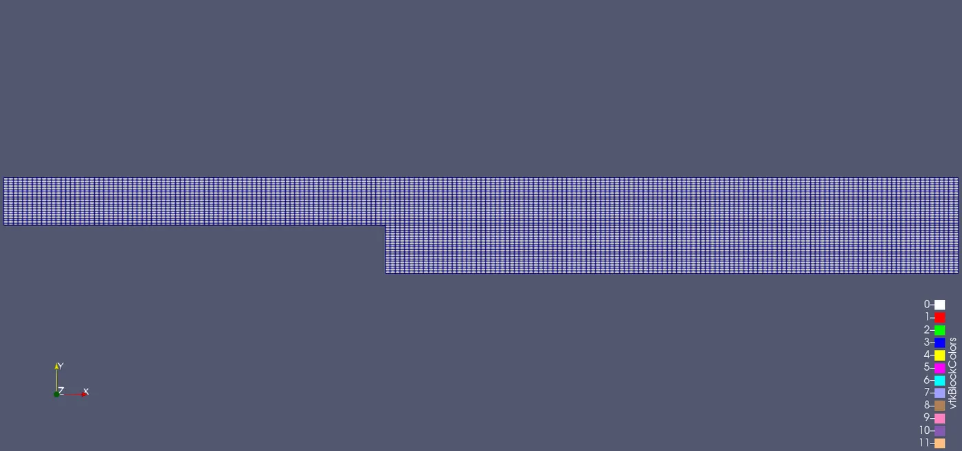
Mesh Model for simple grading 1
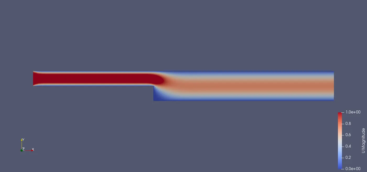
Flow model for simple grading 1
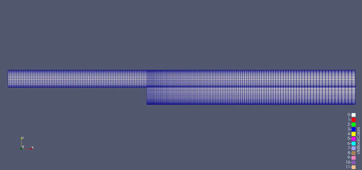
Mesh Model for simple grading 0.2
Flow model for simple grading 0.2
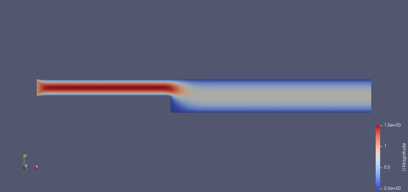
Mesh Model for simple grading 0.5
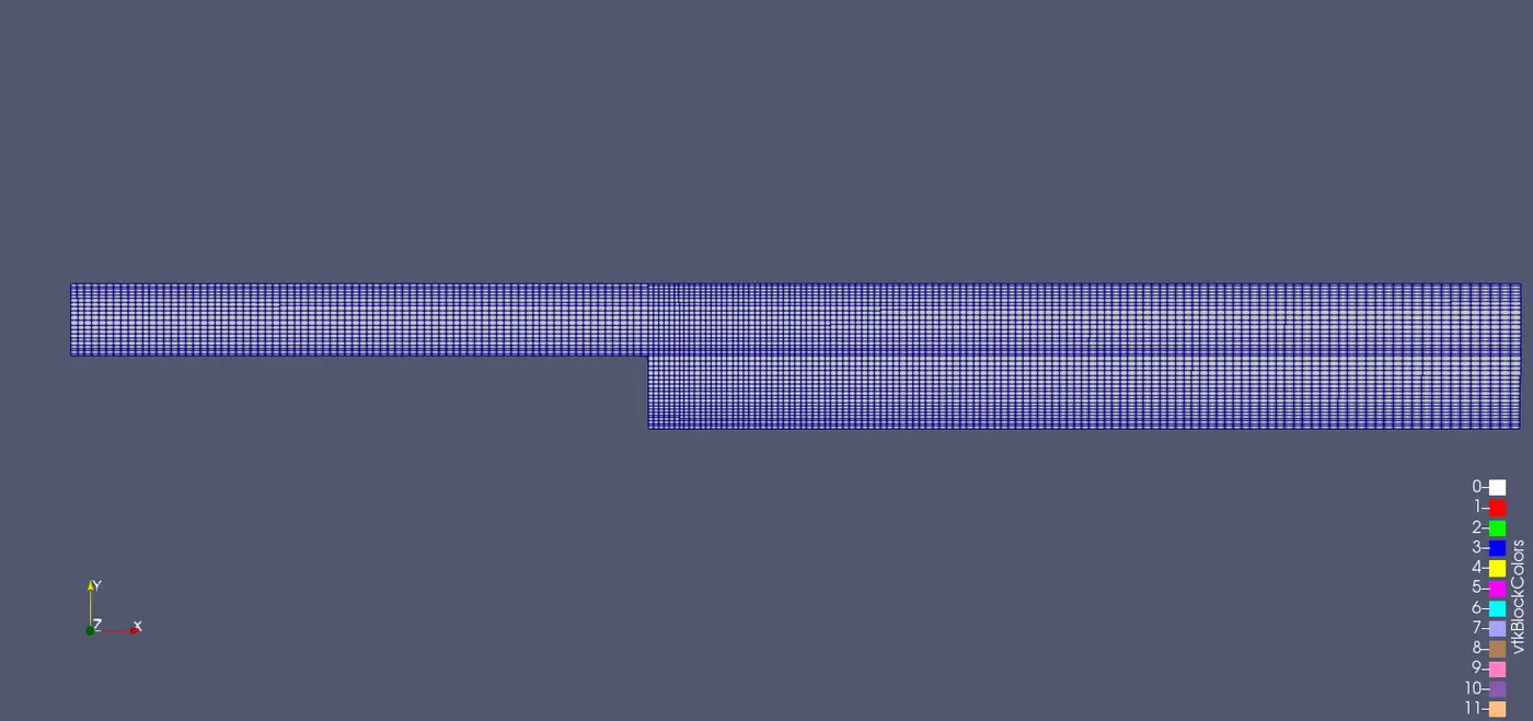
Flow model for simple grading 0.5
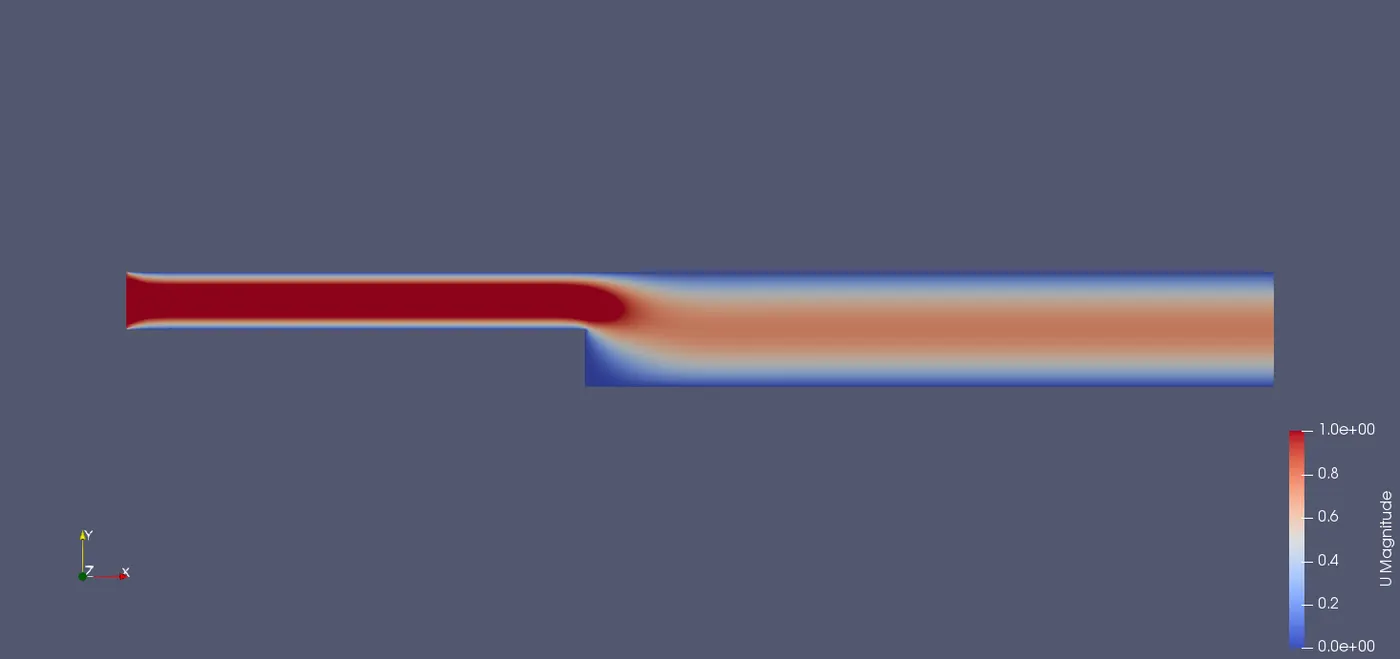
Mesh Model for simple grading 0.8
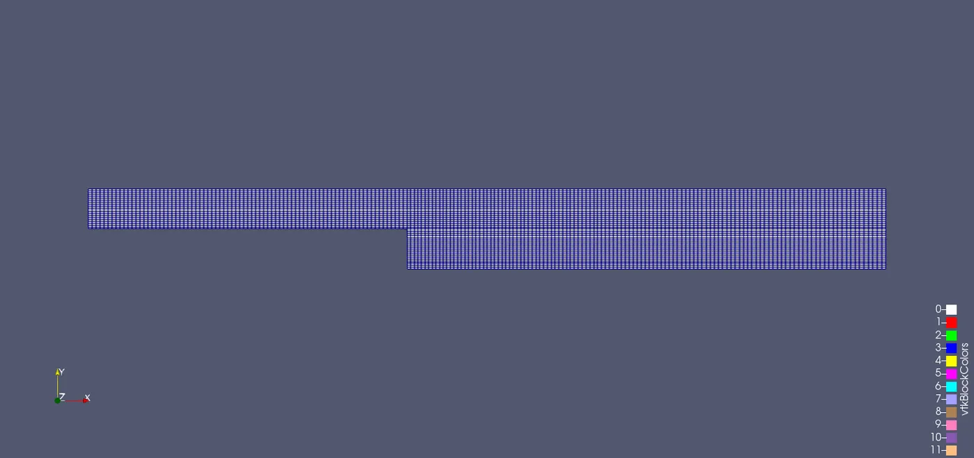
Flow model for simple grading 0.8
Output Line plot for different grading:
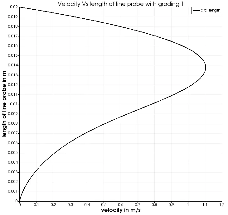
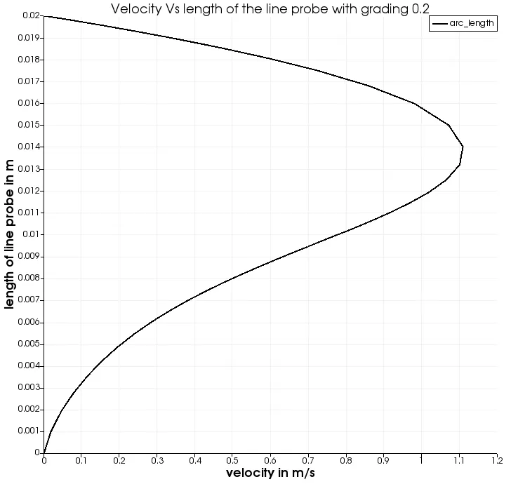
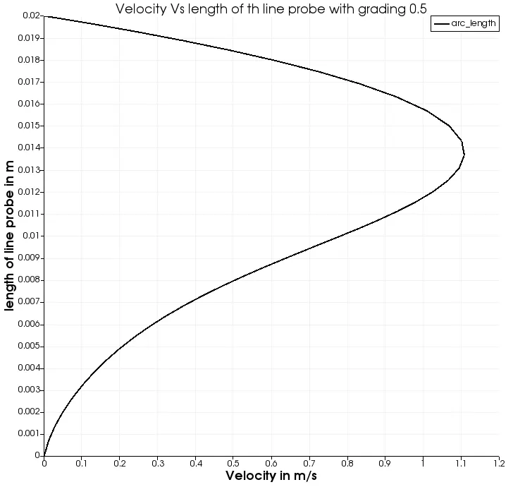
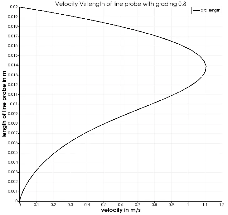
Line over plot command in the common toolbar is used in the ParaView window to obtain a line plot. The line probe is positioned at 0.085m from the inlet of the model parallel to the y-axis.
The velocity is measured at 0.085m from the inlet along the length of the line probe that is for the length of 0.02 m. The profile obtained is the velocity flow profile plotted against the length of the line probe.
1. Line plot for simple grading 1
2. Line plot for simple grading 0.2
3. Line plot with simple grading 0.5
4. Line plot with simple grading 0.8
Conclusion:
The velocity profiles obtained are all similar since minor changes in the grading is been applied. Finer mesh generation will result in higher accuracy of the results and the velocity profiles will be captured accurately for the flow since the boundary layers are formed at the fixed walls.
Velocity data at 0.085m from the inlet is extracted for different grading mentioned in the problem and attached in .csv format.