BlockMesh Drill down simulation using OpenFOAM
BlockMesh Drill down simulation using OpenFoam
AIM:
- Run an incompressible transient flow blockmesh simulation on a drill down using OpenFoam.
OBJECTIVES OF THE PROJECT:
- Specify the boundary mesh and create the right meshing for the structure.
- Define the initial conditions for pressure and velocity of the flow.
- Run the simulation for different values of mesh grading factor.
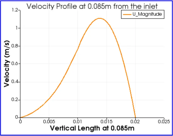
- Evaluate the velocity profile at 0.085m from the inlet.
THEORY:
To start the programming in OpenFoam:
The specific solver or tutorial is to be copied from the respective directory to run directory.
In this case, the incompressible transient flow solver for newtonian fluids will be used- IcoFoam solver.
In the IcoFoam solver, two bodies are input. The cavity folder is copied into the run directory. Inside cavity, inside the systems folder the Boundary Mesh directory is to be opened and updated. The diagram for the structure is given below:
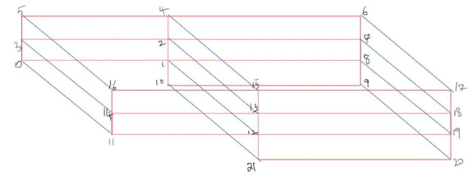
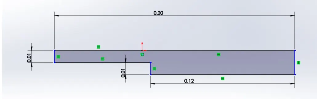
Each of the vertices for the given dimensions of the cavity specified is input. For the later stages of the programme, the vertices mentioned would only be used to navigate to the wall or block mentioned.
The blocks of each section are mentioned for meshing.
The next stage of the programme includes definition of the surfaces. Naming is given as inlet, outlet, no slip wall and fixed wall. The prescribed types of walls and the wall surfaces are input.
After this, the control directory is opened to input the start and stop time, and the time step for the simultion.
No entering into the main cavity directory, the '0' folder refers to the initial conditions for the simulation. The pressure and velocity files are edited with the initial conditions. As in if a fixed value is required, or the gradient remains constant. The direction of velocity flow is also defined. This is done for all the walls specified.
The BlockMesh command is run to create the mesh as instructed. CheckMesh command can be used to check if the mesh is successfully designated for the simulation. IcoFoam command is used to continue with the simulation. ParaFoam command is used to open the ParaView GUI and observed the variation of velocity and pressure for the input simulation time.
To vary the mesh grading factor, the Boundary Mesh Dict file is opened and the simpleGrading(x y z) section is edited in the block creation section.
The grading factor is input as `f=(text(Size of end cell))/(text(Size of start cell))`, and each 3 values are defined for each direction x,y and z.
The mesh grading factor is input based on the boundary wall conditions and the positioning of the adjacent blocks. Initially, a block is selected and based on the intricacies of the flow, the mesh grading is specified in x,y and z directions. The mesh grading should be continuous with the grading lines of the adjacent block, for the mesh lines to be linked. If a block is positioned above the boundary block, the y- dirction meshing should be consistent, if it is aligned along the y-axis, then the the y-axis mesh lines should be consistent. This way all the blocks meshing is decided and input.
BODY OF THE CONTENT:
BLOCKMESH DICT FILE:
/*--------------------------------*- C++ -*----------------------------------*
  =========                 |
        /  F ield         | OpenFOAM: The Open Source CFD Toolbox
       /   O peration     | Website:  https://openfoam.org
      /    A nd           | Version:  8
     /     M anipulation  |
*---------------------------------------------------------------------------*/
FoamFile
{
    version     2.0;
    format      ascii;
    class       dictionary;
    object      blockMeshDict;
}
// * * * * * * * * * * * * * * * * * * * * * * * * * * * * * * * * * * * * * //

convertToMeters 0.01;

vertices
(
    (0 0 0) //0
    (8 0 0) //1
    (8 0.5 0)  //2
    (0 0.5 0) //3
    (8 1 0) //4
    (0 1 0)  //5
    (20 1 0) //6
    (20 0.5 0) //7
    (20 0 0) //8
    (20 -1 0) //9
    (8 -1 0) //10
    (0 0 0.1) //11
    (8 0 0.1) //12
    (8 0.5 0.1) //13
    (0 0.5 0.1) //14
    (8 1 0.1) //15
    (0 1 0.1) //16
    (20 1 0.1) //17
    (20 0.5 0.1) //18
    (20 0 0.1) //19
    (20 -1 0.1) //20
    (8 -1 0.1) //21
);

blocks
(
    hex (0 1 2 3 11 12 13 14) (200 10 1) simpleGrading (1 1 1)
    hex (3 2 4 5 14 13 15 16) (200 10 1) simpleGrading (1 1 1)
    hex (2 7 6 4 13 18 17 15) (200 10 1) simpleGrading (1 1 1)
    hex (1 8 7 2 12 19 18 13) (200 10 1) simpleGrading (1 1 1)
    hex (10 9 8 1 21 20 19 12) (200 10 1) simpleGrading (1 1 1)

);

edges
(
);

boundary
(
    inlet
    {
        type patch;
        faces
        (
            (0 11 14 3)
            (3 14 16 5)
        );
    }
    outlet
    {
        type patch;
        faces
        (
            (9 8 19 20)
            (8 7 18 19)
            (7 6 17 18)
        );
    }
    frontAndBack
    {
        type empty;
        faces
        (
            (0 3 2 1)
            (3 5 4 2)
            (10 1 8 9)
            (1 2 7 8)
            (2 4 6 7)
            (11 12 13 14)
            (14 13 15 16)
            (21 20 19 12)
            (12 19 18 13)
            (13 18 17 15)
        );
    }
    noslipwalls
    {
        type wall;
        faces
        (
            (5 16 15 4)
            (4 15 17 6)
            (0 1 12 11)
            (10 21 12 1)
            (10 9 20 21)
        );
    }
);

mergePatchPairs
(
);

// ************************************************************************* //
VELOCITY INITIAL CONDITIONS FILE:
/*--------------------------------*- C++ -*----------------------------------*
  =========                 |
        /  F ield         | OpenFOAM: The Open Source CFD Toolbox
       /   O peration     | Website:  https://openfoam.org
      /    A nd           | Version:  8
     /     M anipulation  |
*---------------------------------------------------------------------------*/
FoamFile
{
    version     2.0;
    format      ascii;
    class       volVectorField;
    object      U;
}
// * * * * * * * * * * * * * * * * * * * * * * * * * * * * * * * * * * * * * //

dimensions      [0 1 -1 0 0 0 0];

internalField   uniform (0 0 0);

boundaryField
{
    inlet
    {
        type            fixedValue;
        value           uniform (1 0 0);
    }
    outlet
    {
      type             zeroGradient;
    {

    noslipwalls
    {
        type            noSlip;
    }

    frontAndBack
    {
        type            empty;
    }
}

// ************************************************************************* //
PRESSURE INITIAL CONDITIONS FILE:
/*--------------------------------*- C++ -*----------------------------------*
  =========                 |
        /  F ield         | OpenFOAM: The Open Source CFD Toolbox
       /   O peration     | Website:  https://openfoam.org
      /    A nd           | Version:  8
     /     M anipulation  |
*---------------------------------------------------------------------------*/
FoamFile
{
    version     2.0;
    format      ascii;
    class       volScalarField;
    object      p;
}
// * * * * * * * * * * * * * * * * * * * * * * * * * * * * * * * * * * * * * //

dimensions      [0 2 -2 0 0 0 0];

internalField   uniform 0;

boundaryField
{
    inlet
    {
        type            zeroGradient;
    }
    outlet
    {
        type            fixedValue;
        value           uniform 0;
    }
    noslipwalls
    {
        type            zeroGradient;
    }

    frontAndBack
    {
        type            empty;
    }
}

// ************************************************************************* //
BLOCKMESH DICT FILE for MESH GRADDING FACTOR '0.2':
blocks
(
    hex (0 1 2 3 11 12 13 14) (200 10 1) simpleGrading (0.2 5 1)
    hex (3 2 4 5 14 13 15 16) (200 10 1) simpleGrading (0.2 0.2 1)
    hex (2 7 6 4 13 18 17 15) (200 10 1) simpleGrading (5 0.2 1)
    hex (1 8 7 2 12 19 18 13) (200 10 1) simpleGrading (5 5 1)
    hex (10 9 8 1 21 20 19 12) (200 10 1) simpleGrading (5 5 1)

);
BLOCKMESH DICT FILE for MESH GRADDING FACTOR '0.5':
blocks
(
    hex (0 1 2 3 11 12 13 14) (200 10 1) simpleGrading (0.5 2 1)
    hex (3 2 4 5 14 13 15 16) (200 10 1) simpleGrading (0.5 0.5 1)
    hex (2 7 6 4 13 18 17 15) (200 10 1) simpleGrading (2 0.5 1)
    hex (1 8 7 2 12 19 18 13) (200 10 1) simpleGrading (2 2 1)
    hex (10 9 8 1 21 20 19 12) (200 10 1) simpleGrading (2 2 1)

);
BLOCKMESH DICT FILE for MESH GRADDING FACTOR '0.8':
blocks
(
    hex (0 1 2 3 11 12 13 14) (200 10 1) simpleGrading (0.8 1.25 1)
    hex (3 2 4 5 14 13 15 16) (200 10 1) simpleGrading (0.8 0.8 1)
    hex (2 7 6 4 13 18 17 15) (200 10 1) simpleGrading (1.25 0.8 1)
    hex (1 8 7 2 12 19 18 13) (200 10 1) simpleGrading (1.25 1.25 1)
    hex (10 9 8 1 21 20 19 12) (200 10 1) simpleGrading (1.25 1.25 1)

);
OUTPUT:
Uniform Mesh Grading Output:
Velocity Distribution Pressure Distribution
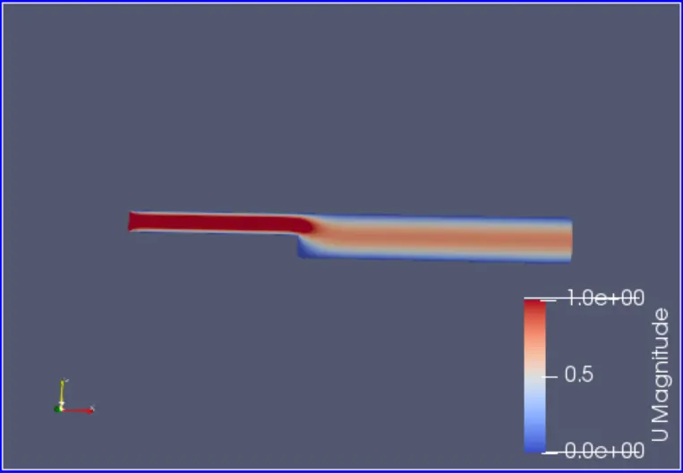
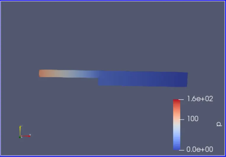
Velocity Profile on a vertical line at 0.085m from the inlet
Mesh Grading Factor '0.2' Output:
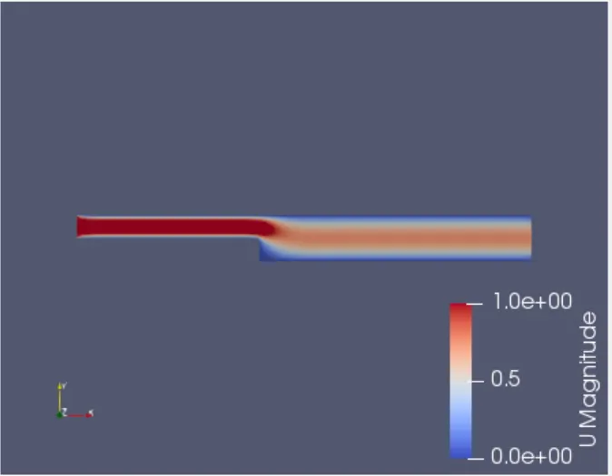
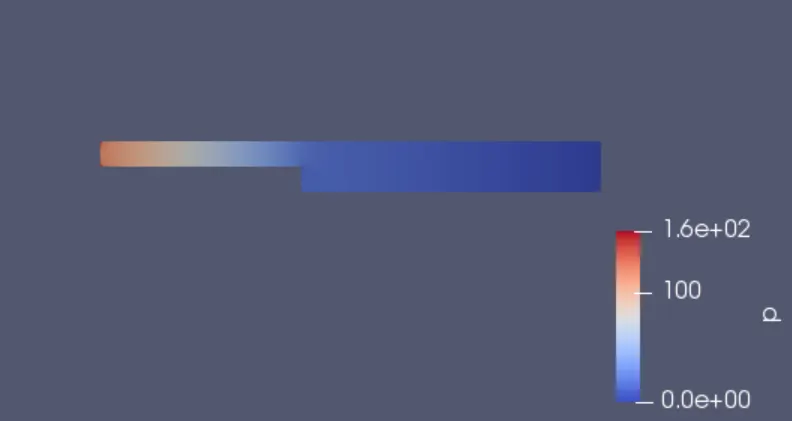
Velocity Distribution Pressure Distribution
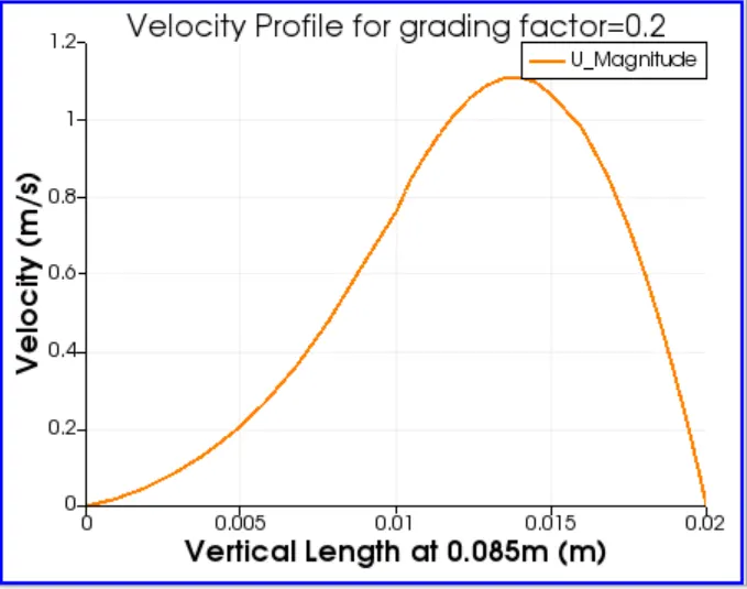
Velocity Profile on a vertical line at 0.085m from the inlet
Mesh Grading Factor '0.5' Output:
Velocity Distribution Pressure Distribution
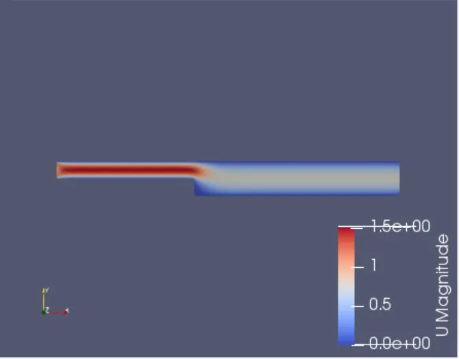
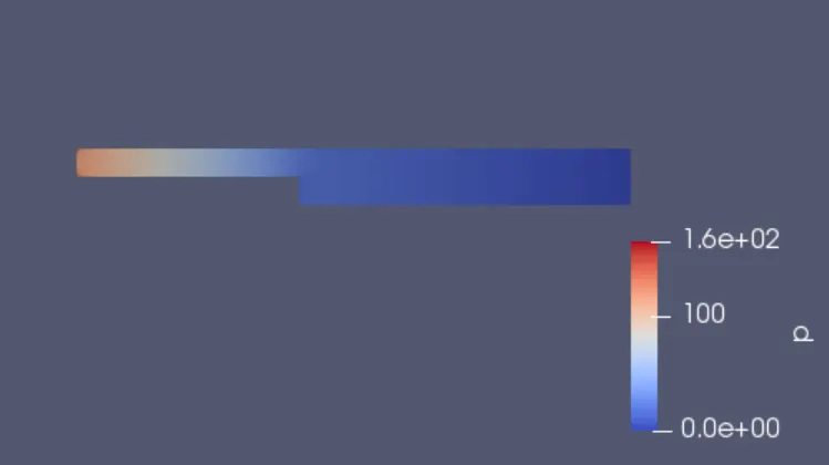
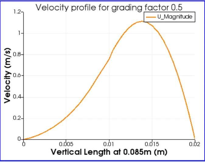
Velocity Profile on a vertical line at 0.085m from the inlet
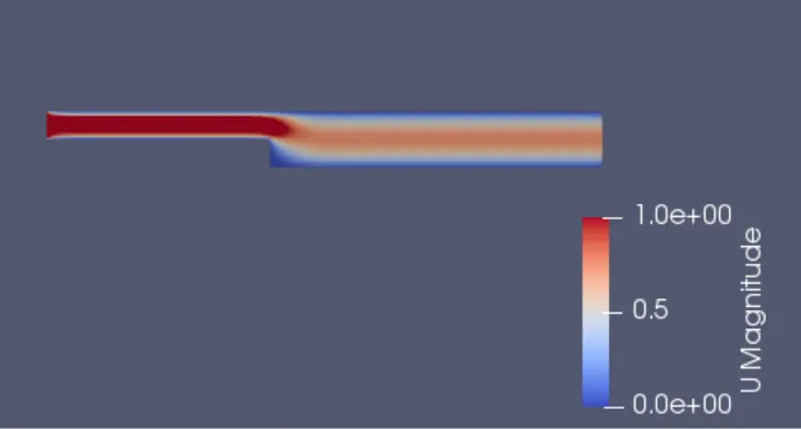
Mesh Grading Factor '0.8' Output:
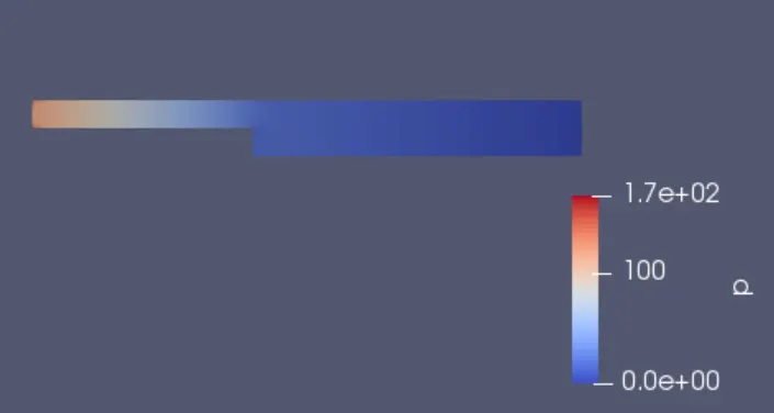
Velocity Distribution
Pressure Distribution
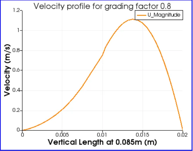
Velocity Profile on a vertical line at 0.085m from the inlet
CONCLUSION:
The simulations were succesfully run and the outputs stored in the respective time interval directories in the cavity directory.
Comparing the results obtained by each simulation, overall each plot shows negligible difference. Although on a microscopic level, the meshing might have effected the velocity and pressure distributions.
For a complex flow, the change in grading factor can help understand and visualize the flow properties better.
The velocity for each flow at (0.085,0) in the cavity varies as: 0.62066 m/s, 0.62868 m/s and 0.63442 m/s for the grading factors 0.2,0.5 and 0.8 respectively.