Week 8 - BlockMesh Drill down challenge
In OpenFOAM, any given domain is initially divided into certain no. of blocks each having specific no. of vertices.
These vertices and blocks are defined in a flle called "blockMeshDict".
Generation of blocks and meshing in "blockMeshDict" file:
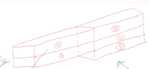
The domain is divided into blocks as below
Now each vertex should be given a number so that all the patches can be defined.
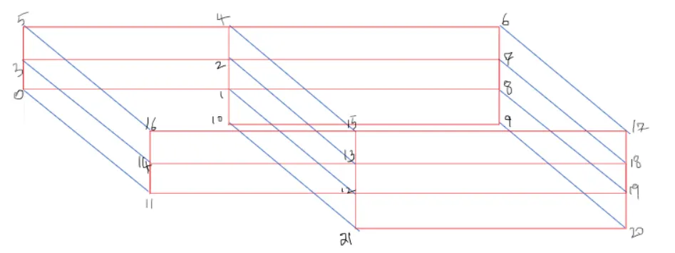
According to the given dimensions, each vertex has coordinates as
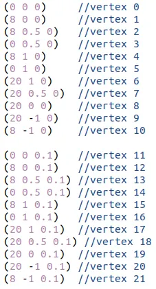
These are all multipled coverted to metres by multiplying with 0.01.
Next is to define each block and provide mesh and grading factors.
For example, for defining the first block, it should be written as
(0 1 2 3 11 12 13 14) (80 5 1) (1 5 1) -
0 defines origin and writing 1 after 0 means that the positive X axis is from 0->1. Writing 2 after 1 means that the positive Y axis is fomr 1->2.
(80 5 1) defines the mesh - length in the X direction in that block is divided into 80 cells, breadth in Y direction into 5 cells, thickness into Z direction into 1 cell(as it is a 2D problem).
(1 5 1) defines the grading factor -
Grading factor = (size of end cell)/(size of start cell)
So, in the Y direction, size of start cell at no slip boundary is 0.2 times of size of end cell. This makes the cell size at start small.
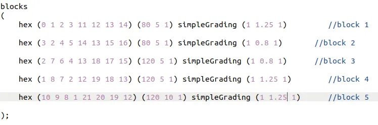
Likewise, different grading factors 0.5 and 0.8 are considered to check their influence on solution.
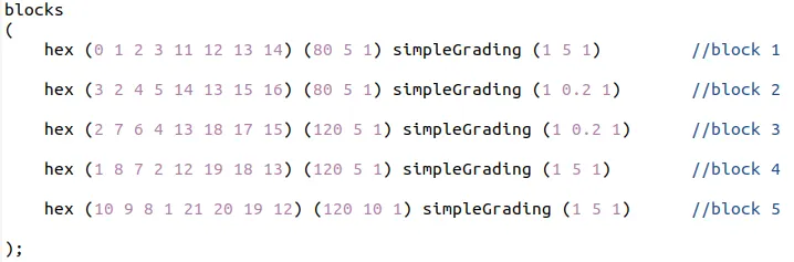
Similarly, other blocks are defined according to the geometry as
Next step is to define each boundary and label them.
For example, lets consider inlet boundary
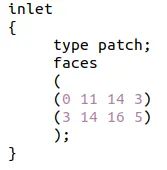
The inlet boundary is labelled as "inlet". For the inlet and outlet boundaries, the type is given as patch. The faces that constitute the inlet boundary are mentioned by following right hand thumb rule.
Similalrly, no slip wall and front and back boundaries are also defined.
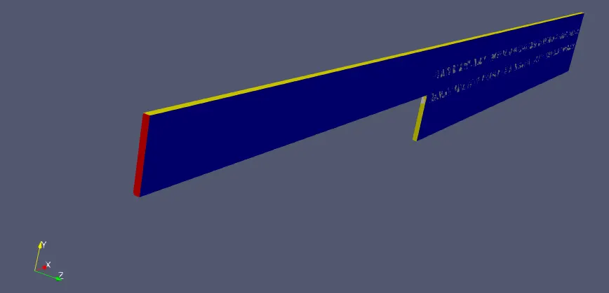
BlockMeshDict for grading factor 0.2:
/*--------------------------------*- C++ -*----------------------------------*\
  =========                 |
  \\      /  F ield         | OpenFOAM: The Open Source CFD Toolbox
   \\    /   O peration     | Website:  https://openfoam.org
    \\  /    A nd           | Version:  8
     \\/     M anipulation  |
\*---------------------------------------------------------------------------*/
FoamFile
{
    version     2.0;
    format      ascii;
    class       dictionary;
    object      blockMeshDict;
}
// * * * * * * * * * * * * * * * * * * * * * * * * * * * * * * * * * * * * * //

convertToMeters 0.01;

vertices
(
    (0 0 0)     //vertex 0
    (8 0 0)     //vertex 1
    (8 0.5 0)   //vertex 2
    (0 0.5 0)   //vertex 3
    (8 1 0)     //vertex 4
    (0 1 0)     //vertex 5
    (20 1 0)    //vertex 6
    (20 0.5 0)  //vertex 7
    (20 0 0)    //vertex 8
    (20 -1 0)   //vertex 9
    (8 -1 0)    //vertex 10

    (0 0 0.1)   //vertex 11
    (8 0 0.1)   //vertex 12
    (8 0.5 0.1) //vertex 13
    (0 0.5 0.1) //vertex 14
    (8 1 0.1)   //vertex 15
    (0 1 0.1)   //vertex 16
    (20 1 0.1)  //vertex 17
    (20 0.5 0.1) //vertex 18
    (20 0 0.1)  //vertex 19
    (20 -1 0.1) //vertex 20
    (8 -1 0.1)  //vertex 21

);


blocks
(
    hex (0 1 2 3 11 12 13 14) (80 5 1) simpleGrading (1 5 1)         //block 1

    hex (3 2 4 5 14 13 15 16) (80 5 1) simpleGrading (1 0.2 1)       //block 2

    hex (2 7 6 4 13 18 17 15) (120 5 1) simpleGrading (1 0.2 1)      //block 3

    hex (1 8 7 2 12 19 18 13) (120 5 1) simpleGrading (1 5 1)        //block 4

    hex (10 9 8 1 21 20 19 12) (120 10 1) simpleGrading (1 5 1)      //block 5

);

edges
(
);

boundary
(
   inlet
   {
        type patch;
        faces
        (
        (0 11 14 3)
        (3 14 16 5)
        );
   }

   outlet
   {
        type patch;
        faces
        (
        (9 8 19 20)
        (8 7 18 19)
        (7 6 17 18)
        );
   }

   frontAndBack
   {
        type empty;
        faces
        (
        (4 2 3 5)
        (2 1 0 3)
        (6 7 2 4)
        (7 8 1 2)
        (8 9 10 1)
        (16 14 13 15)
        (14 11 12 13)
        (15 13 18 17)
        (13 12 19 18)
        (12 21 20 19)
        );
   }

   noSlipWall
   {
        type wall;
        faces
        (
        (5 16 15 4)
        (4 15 17 6)
        (10 21 12 1)
        (0 1 12 11)
        (10 9 20 21)
        );
   }

);

mergePatchPairs
(
);


// ************************************************************************* //
For grading factor of 0.5,

For grading factor of 0.8,
Initial and Boundary conditions:
Next step is to mention the boundary and initial conditions.
For Velocity:
A fixed inlet velocity of 0.1 m/s is provided in X direction alone.
At the outlet, the boundary type is given as "zeroGradient". It means that the outlet patch extrapolates the values.
Walls with no slip condition are given noSlip.
/*--------------------------------*- C++ -*----------------------------------*\
  =========                 |
  \\      /  F ield         | OpenFOAM: The Open Source CFD Toolbox
   \\    /   O peration     | Website:  https://openfoam.org
    \\  /    A nd           | Version:  8
     \\/     M anipulation  |
\*---------------------------------------------------------------------------*/
FoamFile
{
    version     2.0;
    format      ascii;
    class       volVectorField;
    object      U;
}
// * * * * * * * * * * * * * * * * * * * * * * * * * * * * * * * * * * * * * //

dimensions      [0 1 -1 0 0 0 0];

internalField   uniform (0 0 0);

boundaryField
{

    inlet
    {
        type            fixedValue;
        value           uniform (0.1 0 0);
    }

    outlet
    {
        type            zeroGradient;

    }

    noSlipWall
    {
        type            noSlip;
    }

    frontAndBack
    {
        type            empty;
    }
}

// ************************************************************************* //
For Pressure:
/*--------------------------------*- C++ -*----------------------------------*\
  =========                 |
  \\      /  F ield         | OpenFOAM: The Open Source CFD Toolbox
   \\    /   O peration     | Website:  https://openfoam.org
    \\  /    A nd           | Version:  8
     \\/     M anipulation  |
\*---------------------------------------------------------------------------*/
FoamFile
{
    version     2.0;
    format      ascii;
    class       volScalarField;
    object      p;
}
// * * * * * * * * * * * * * * * * * * * * * * * * * * * * * * * * * * * * * //

dimensions      [0 2 -2 0 0 0 0];

internalField   uniform 0;

boundaryField
{

    inlet
    {
        type            zeroGradient;
    }

    outlet
    {
        type            fixedValue;
        value           uniform 0;
    }

    noSlipWall

    {
        type            zeroGradient;
    }

    frontAndBack
    {
        type            empty;
    }
}

// ************************************************************************* //
Transport Properties:
The fluid flowing ins the domain is assumed as water. The kinematic viscosity of water is 1.787e-6.
/*--------------------------------*- C++ -*----------------------------------*\
  =========                 |
  \\      /  F ield         | OpenFOAM: The Open Source CFD Toolbox
   \\    /   O peration     | Website:  https://openfoam.org
    \\  /    A nd           | Version:  8
     \\/     M anipulation  |
\*---------------------------------------------------------------------------*/
FoamFile
{
    version     2.0;
    format      ascii;
    class       dictionary;
    location    "constant";
    object      transportProperties;
}
// * * * * * * * * * * * * * * * * * * * * * * * * * * * * * * * * * * * * * //

nu              [0 2 -1 0 0 0 0] 1.787e-6;


// ************************************************************************* //
Control Dict:
In this file, time step size and start and end time are given.
Time step size is chosen as 0.005 and total time of simulation is 2 seconds.
/*--------------------------------*- C++ -*----------------------------------*\
  =========                 |
  \\      /  F ield         | OpenFOAM: The Open Source CFD Toolbox
   \\    /   O peration     | Website:  https://openfoam.org
    \\  /    A nd           | Version:  8
     \\/     M anipulation  |
\*---------------------------------------------------------------------------*/
FoamFile
{
    version     2.0;
    format      ascii;
    class       dictionary;
    location    "system";
    object      controlDict;
}
// * * * * * * * * * * * * * * * * * * * * * * * * * * * * * * * * * * * * * //

application     icoFoam;

startFrom       startTime;

startTime       0;

stopAt          endTime;

endTime         2;

deltaT          0.005;

writeControl    timeStep;

writeInterval   20;

purgeWrite      0;

writeFormat     ascii;

writePrecision  6;

writeCompression off;

timeFormat      general;

timePrecision   6;

runTimeModifiable true;


// ************************************************************************* //
Outputs:
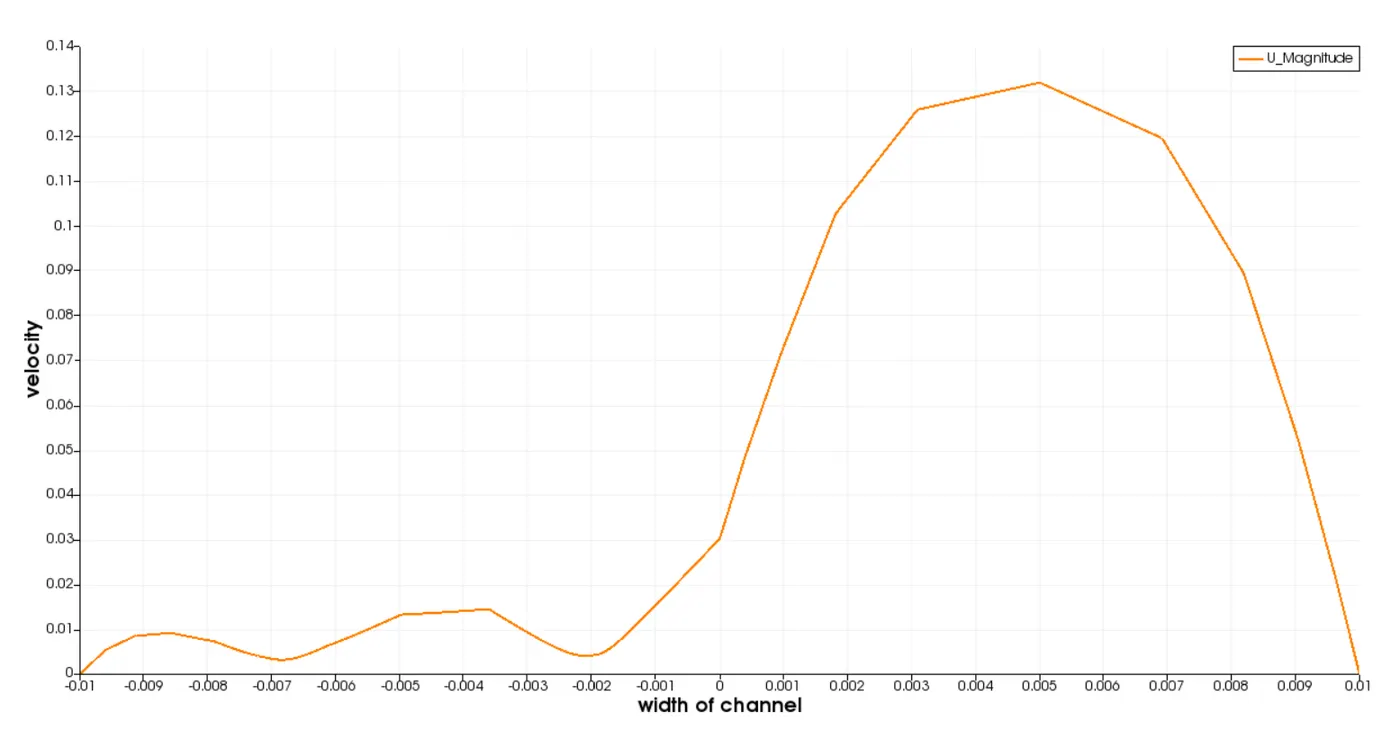
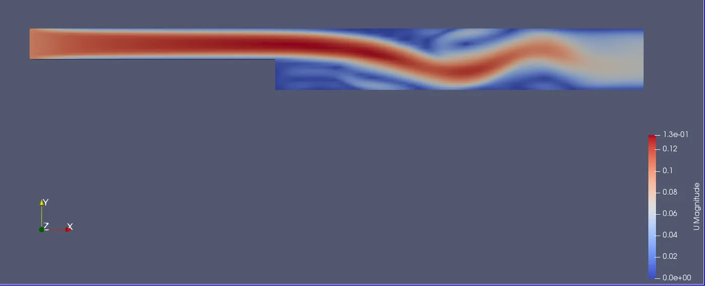
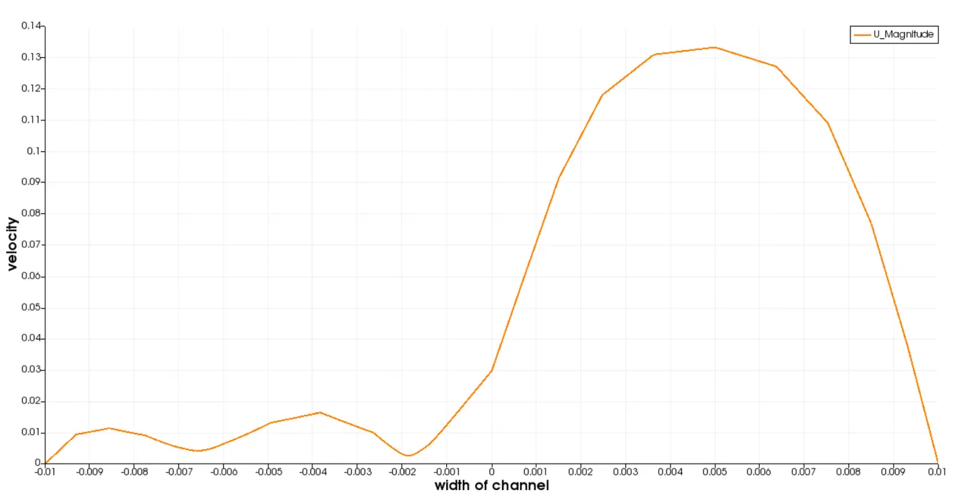
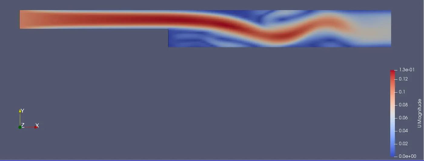
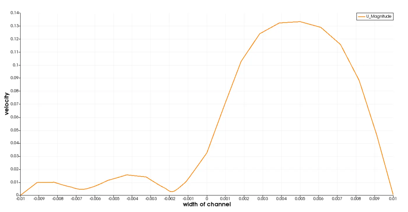
Velocity profile at a distance of x = 0.085 m is found for three different grading factors.
For grading factor of 0.2:
Mesh:

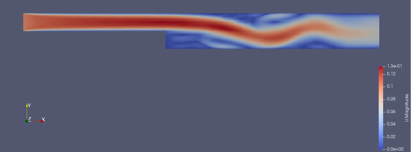
After t = 2 secs:
Velocity distribution:
Velocity profile at x = 0.085 m from origin:
For grading factor of 0.5:
Mesh:

After t = 2 secs:
Velocity distribution:
Velocity profile at x = 0.085 m from origin:
For grading factor of 0.8:
Mesh:

After t = 2 secs:
Velocity distribution:
Velocity profile at x = 0.085 m from origin:
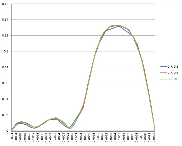
Comparison of velocity distributions for 3 grading factors:
Conclusions:
From the above graph. it is observed that
1. At locations between 0.025m to 0.075m, the velocity distribution is lot smoother for 0.8 GF and 0.5 GF compared to 0.2 GF. This is because the nodal density for 0.2 GF is less between 0.025m and 0.075m compared to 0.5 GF and 0.8 GF. Because the mesh is stretched more at the walls, less nodes are present between 0.025m and 0.075m. Due to this, solution is calculated at less locations which results in less accurate results. Whereas for 0.8 GF, mesh is stretched less at the walls, due to this more nodes are present in between 0.025m and 0.075m and more accurate results are obtained. The 0.5 GF curve has soluton more accurate than 0.2 GF and less accurate than 0.8 GF in between 0.025m and 0.075m.
2. At start of the boundary i.e at locations between 0 and -0.007m, velocity distribution is lot smoother for 0.2 GF compared to 0.5 and 0.8 GF. Due to the more stretching, more nodes are present in that area which results in accurate solution. Whereas for 0.8 GF, as mesh is stretched less at the boundary, the distribution is not smooth by which exact behaviour at the boundary is not obtained. Similar behaviour can be observed for 0.5 GF but the distribution is more smoother compared to 0.8 GF but less than 0.2 GF.
3. Similar behaviour can be observed at locations between -0.003m and -0.001m. Distribution is lot smoother for 0.2 GF compared to 0.5 and 0.8GF because mesh is stretched more in that area.
4. From the above observations, it can be concluded that as mesh grading increases, nodal desnity increases in that area which results in accurate solution/exact behaviour. Also, if the mesh grading is much higher at a particular location, the mesh becomes more coarser at other locations which results in less accurate solution.