Week 8 - BlockMesh Drill down challenge
Objective
This project drills down into some of the intricacy of OpenFOAM's blockMesh utility software used for mesh generation. Specifically, we aim to:
- Perform mesh generation with blockMesh
- Understand the effects of mesh grading on simulated results.
Theory
The blockMesh utility creates parametric meshes with grading and curved edges. The mesh is generated from a dictionary file named blockMeshDict located in the system (or constant/polyMesh) directory of a case. blockMesh reads this dictionary, generates the mesh and writes out the mesh data to points and faces, cell and boundary files in the same directory.
The principle behind blockMesh is to decompose the domain geometry into a set of 1 or more three dimensional, hexahedral blocks. Edges of the blocks can be straight lines, arcs or splines. The mesh is ostensibly specified as a number of cells in each direction of the block, sufficient information for blockMesh to generate the mesh data.
Each block of the geometry is defined by 8 vertices, one at each corner of a hexahedron. The vertices are written in a list so that each vertex can be accessed using its label, remembering that OpenFOAM always uses the C++ convention that the first element of the list has label ‘0’.
Grading Factor
The grading factor or expansion ratio enables the mesh to be graded or refined, in specified directions. The ratio is that of the width of the end cell `delta_e` along one edge of a block to the width of the start cell `delta_s` along that edge,
Grading Factor = `(delta_e)/(delta_s)`
This has the effect of squeezing the cells together at certain locations and stretching them at other locations.
The reason why this is necessary is because in some applications, like turbulent flows or expansion flows, certain regions( e.g. boundary layers) experience rapid variations in the parameter values and their length scales are very small compared to the overall length scale of the domain. If we would like to capture these phenomena, we have to decrease the grid size or cell size in those regions hence, the grading factor. Conversely, Certain regions do not experience rapid change; example, the free stream. The length scale can be increased in these areas and still accurately capture the phenomenon.
Analysis
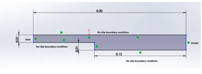
Present analysis involves three sets of mesh generated for a back-facing step with the following parameters:
- Number of cells along the x direction (longer dimension) = 200
- Number of cells along the y direction = 10
- Grading factors near all walls = 0.2, 0.5, 0.8 respectively.
The back-facing step geometry and fluid domain used are displayed below.
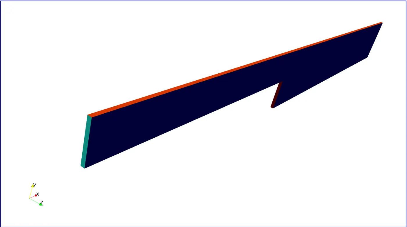
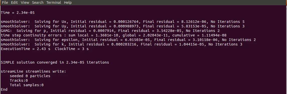
Simulation was then done for an incompressible turbulent flow using the Semi-Implicit Method for Presssure-Linked Equation (SIMPLE) algorithm. This is the simpleFoam in OpenFOAM. The parameters used initially are:
`"Re" = 800`
`U_infty = 1.2 m"/"s`
`k = 0.00540 m^2"/"s^2`
`epsilon = 0.00540 m^2"/"s^3`
`mu_t"/"mu = 100`
The results are now presented according to grading factor used for the mesh. Based on the present scope and objectives, the facts of the flow simulations were not detailed. The blockMeshdict file and the initial conditions files for various parameters are however displayed below.
/*--------------------------------*- C++ -*----------------------------------*\
  =========                 |
  \\      /  F ield         | OpenFOAM: The Open Source CFD Toolbox
   \\    /   O peration     | Website:  https://openfoam.org
    \\  /    A nd           | Version:  7
     \\/     M anipulation  |
\*---------------------------------------------------------------------------*/
FoamFile
{
    version     2.0;
    format      ascii;
    class       dictionary;
    object      blockMeshDict;
}
// * * * * * * * * * * * * * * * * * * * * * * * * * * * * * * * * * * * * * //

convertToMeters 1;

vertices
(
    (0 0 0)              //0
    (0.08 0 0)           //1
    (0.08 0.005 0)       //2
    (0 0.005 0)          //3
    (0 0 0.001)          //4
    (0.08 0 0.001)       //5
    (0.08 0.005 0.001)   //6
    (0 0.005 0.001)      //7

    (0.08 0.01 0)       //8
    (0 0.01 0)          //9
    (0 0.01 0.001)      //10
    (0.08 0.01 0.001)   //11

    (0.08 -0.01 0)      //12
    (0.2 -0.01 0)       //13
    (0.2 0 0)           //14
    (0.08 -0.01 0.001)  //15


    (0.2 -0.01 0.001)    //16
    (0.2 0 0.001)        //17
    (0.2 0.005 0)        //18
    (0.2 0.01 0)         //19

    (0.2 0.005 0.001)    //20
    (0.2 0.01 0.001)     //21


);


blocks
(
    hex (0 1 2 3 4 5 6 7) (80 10 1) simpleGrading (0.2 5 1)
    hex (3 2 8 9 7 6 11 10) (80 10 1) simpleGrading (0.2 0.2 1)


    hex (2 18 19 8 6 20 21 11) (120 10 1) simpleGrading (5 0.2 1)
    hex (1 14 18 2 5 17 20 6) (120 10 1) simpleGrading (5 5 1)
    hex (12 13 14 1 15 16 17 5) (120 10 1) simpleGrading (5 5 1)

);

edges
(
);

boundary
(
    inlet
    {
        type patch;
        faces
        (
            (0 4 7 3)
            (3 7 10 9)
        );
    }
    outlet
    {
        type patch;
        faces
        (
            (18 19 21 20)
            (14 18 20 17)
            (13 14 17 16)
        );
    }
    upperWall
    {
        type wall;
        faces
        (
            (9 10 11 8)
            (8 11 21 19)
        );
    }
    lowerWall
    {
        type wall;
        faces
        (
            (0 1 5 4)
            (12 15 5 1)
            (12 13 16 15)
        );
    }
    frontAndBack
    {
        type empty;
        faces
        (
            (0 3 2 1)
            (3 9 8 2)
            (2 8 19 18)
            (1 2 18 14)
            (12 1 14 13)

            (4 5 6 7)
            (7 6 11 10)
            (6 20 21 11)
            (5 17 20 6)
            (15 16 17 5)
        );
    }
);

mergePatchPairs
(

);

// ************************************************************************* //
/*--------------------------------*- C++ -*----------------------------------*\
========= |
\\ / F ield | OpenFOAM: The Open Source CFD Toolbox
\\ / O peration | Website: https://openfoam.org
\\ / A nd | Version: 7
\\/ M anipulation |
\*---------------------------------------------------------------------------*/
FoamFile
{
version 2.0;
format ascii;
class dictionary;
location "system";
object controlDict;
}
// * * * * * * * * * * * * * * * * * * * * * * * * * * * * * * * * * * * * * //
application simpleFoam;
startFrom startTime;
startTime 0;
stopAt endTime;
endTime 1e-4;
deltaT 1e-7;
writeControl adjustableRunTime;
writeInterval 5e-7;
purgeWrite 0;
writeFormat ascii;
writePrecision 6;
writeCompression off;
timeFormat general;
timePrecision 6;
runTimeModifiable true;
functions
{
#includeFunc streamlines
}
// ************************************************************************* ///*--------------------------------*- C++ -*----------------------------------*\
========= |
\\ / F ield | OpenFOAM: The Open Source CFD Toolbox
\\ / O peration | Website: https://openfoam.org
\\ / A nd | Version: 7
\\/ M anipulation |
\*---------------------------------------------------------------------------*/
FoamFile
{
version 2.0;
format ascii;
class volScalarField;
object p;
}
// * * * * * * * * * * * * * * * * * * * * * * * * * * * * * * * * * * * * * //
dimensions [0 2 -2 0 0 0 0];
internalField uniform 0;
boundaryField
{
inlet
{
type zeroGradient;
}
outlet
{
type fixedValue;
value uniform 0;
}
upperWall
{
type zeroGradient;
}
lowerWall
{
type zeroGradient;
}
frontAndBack
{
type empty;
}
}
// ************************************************************************* ///*--------------------------------*- C++ -*----------------------------------*\
========= |
\\ / F ield | OpenFOAM: The Open Source CFD Toolbox
\\ / O peration | Website: https://openfoam.org
\\ / A nd | Version: 7
\\/ M anipulation |
\*---------------------------------------------------------------------------*/
FoamFile
{
version 2.0;
format ascii;
class volVectorField;
object U;
}
// * * * * * * * * * * * * * * * * * * * * * * * * * * * * * * * * * * * * * //
dimensions [0 1 -1 0 0 0 0];
internalField uniform (0 0 0);
boundaryField
{
inlet
{
type fixedValue;
value uniform (1.2 0 0);
}
outlet
{
type zeroGradient;
}
upperWall
{
type noSlip;
}
lowerWall
{
type noSlip;
}
frontAndBack
{
type empty;
}
}
// ************************************************************************* ///*--------------------------------*- C++ -*----------------------------------*\
========= |
\\ / F ield | OpenFOAM: The Open Source CFD Toolbox
\\ / O peration | Website: https://openfoam.org
\\ / A nd | Version: 7
\\/ M anipulation |
\*---------------------------------------------------------------------------*/
FoamFile
{
version 2.0;
format ascii;
class volScalarField;
location "0";
object k;
}
// * * * * * * * * * * * * * * * * * * * * * * * * * * * * * * * * * * * * * //
dimensions [0 2 -2 0 0 0 0];
internalField uniform 0.00175;
boundaryField
{
inlet
{
type fixedValue;
value uniform 0.00175;
}
outlet
{
type zeroGradient;
}
upperWall
{
type kqRWallFunction;
value uniform 0.00175;
}
lowerWall
{
type kqRWallFunction;
value uniform 0.00175;
}
frontAndBack
{
type empty;
}
}
// ************************************************************************* ///*--------------------------------*- C++ -*----------------------------------*\
========= |
\\ / F ield | OpenFOAM: The Open Source CFD Toolbox
\\ / O peration | Website: https://openfoam.org
\\ / A nd | Version: 7
\\/ M anipulation |
\*---------------------------------------------------------------------------*/
FoamFile
{
version 2.0;
format ascii;
class volScalarField;
location "0";
object epsilon;
}
// * * * * * * * * * * * * * * * * * * * * * * * * * * * * * * * * * * * * * //
dimensions [0 2 -3 0 0 0 0];
internalField uniform 5.4e-3;
boundaryField
{
inlet
{
type fixedValue;
value uniform 5.4e-3;
}
outlet
{
type zeroGradient;
}
upperWall
{
type epsilonWallFunction;
value uniform 5.4e-3;
}
lowerWall
{
type epsilonWallFunction;
value uniform 5.4e-3;
}
frontAndBack
{
type empty;
}
}
// ************************************************************************* ///*--------------------------------*- C++ -*----------------------------------*\
========= |
\\ / F ield | OpenFOAM: The Open Source CFD Toolbox
\\ / O peration | Website: https://openfoam.org
\\ / A nd | Version: 7
\\/ M anipulation |
\*---------------------------------------------------------------------------*/
FoamFile
{
version 2.0;
format ascii;
class volScalarField;
location "0";
object nut;
}
// * * * * * * * * * * * * * * * * * * * * * * * * * * * * * * * * * * * * * //
dimensions [0 2 -1 0 0 0 0];
internalField uniform 1.5e-3;
boundaryField
{
inlet
{
type calculated;
value uniform 1.5e-3;
}
outlet
{
type calculated;
value uniform 1.5e-3;
}
upperWall
{
type nutkWallFunction;
value uniform 1.5e-3;
}
lowerWall
{
type nutkWallFunction;
value uniform 1.5e-3;
}
frontAndBack
{
type empty;
}
}
// ************************************************************************* //Results
Grading factor = 0.2
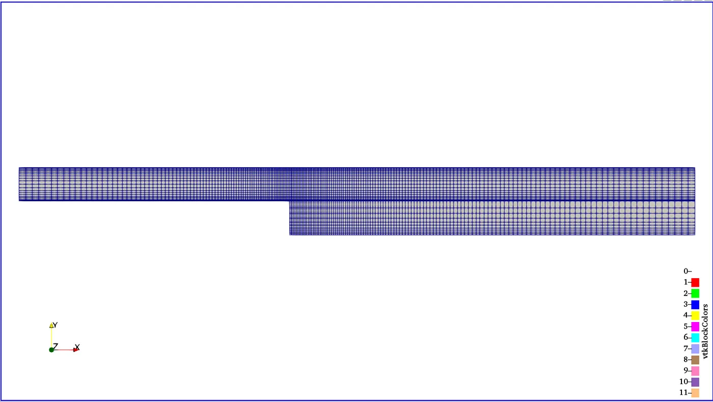
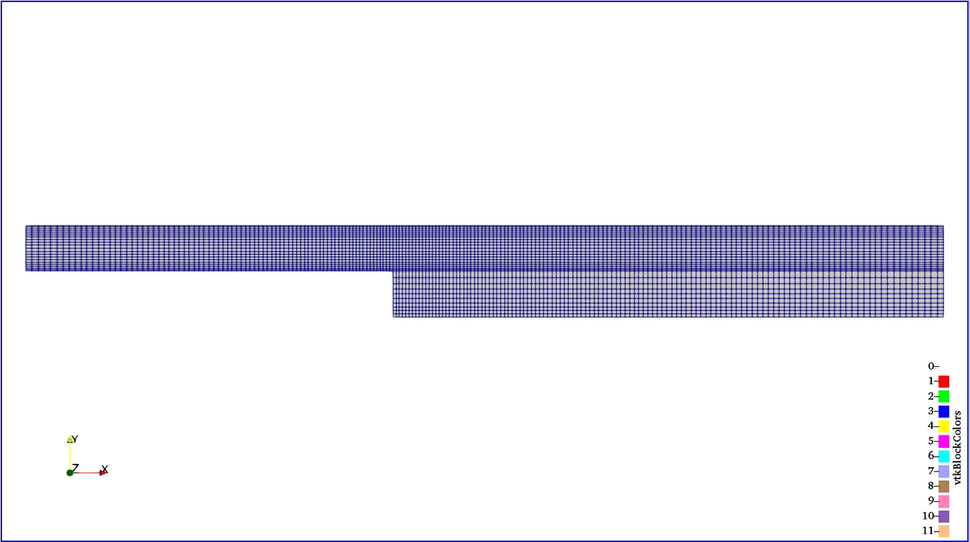
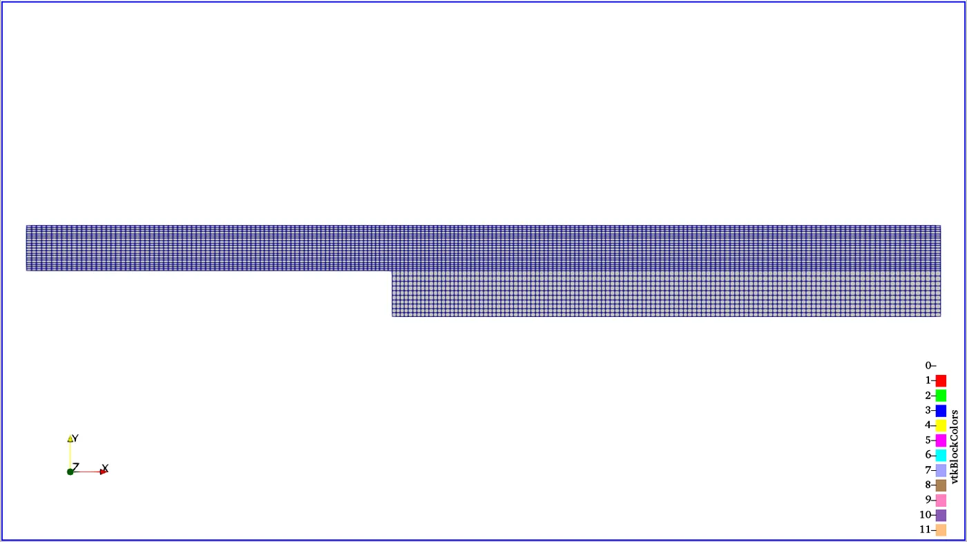
The image after that is the mesh for the geometry using the grading factor of 0.2 near the walls. The essence of grading is to capture near-wall boundary layer phenomenon.
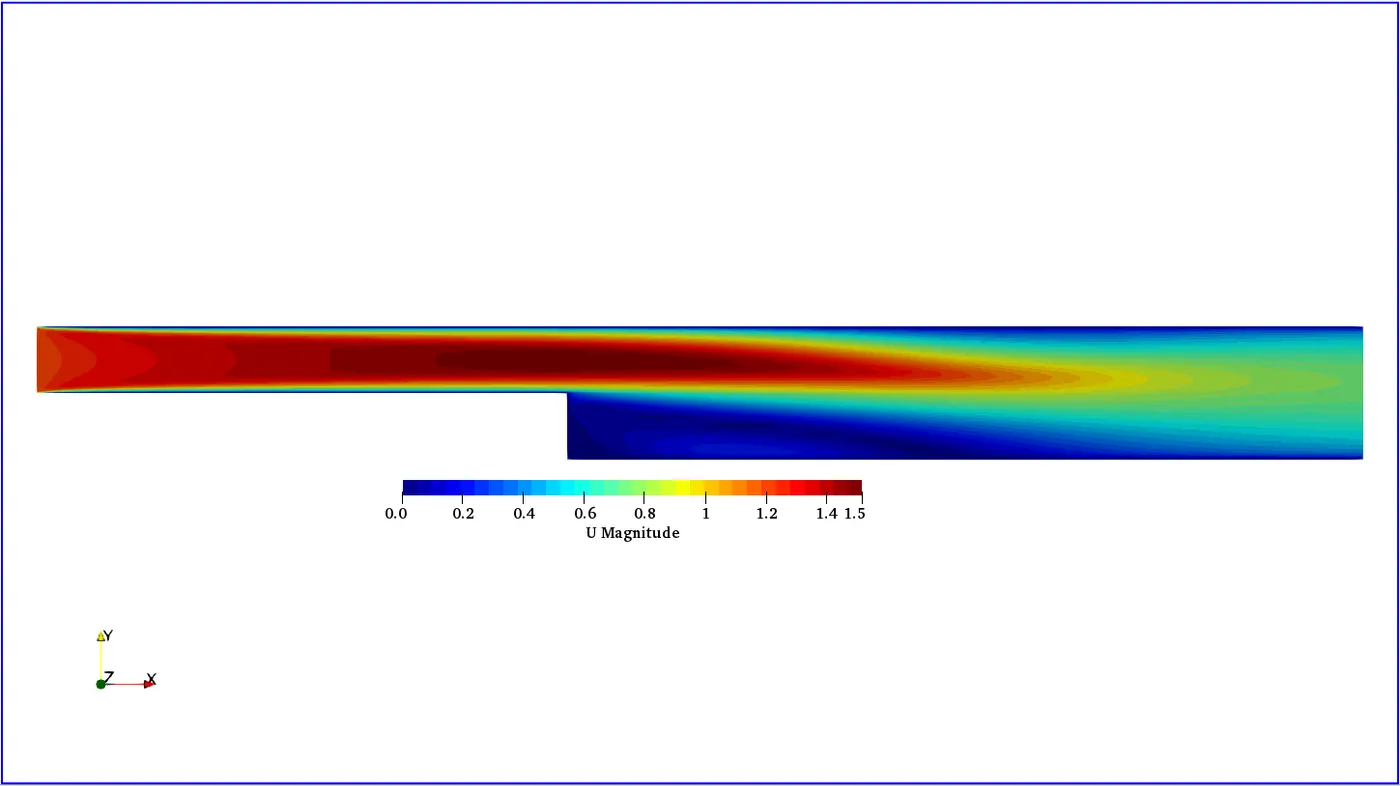
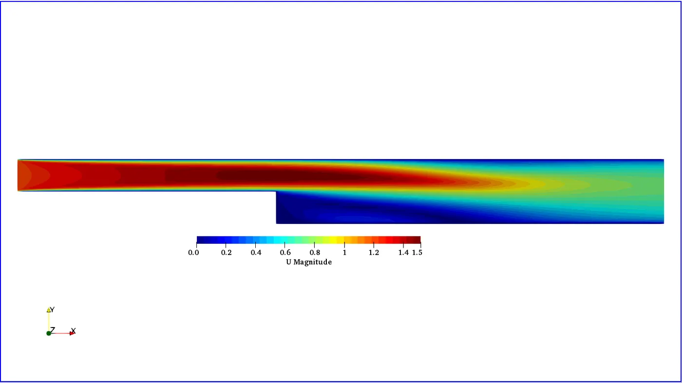
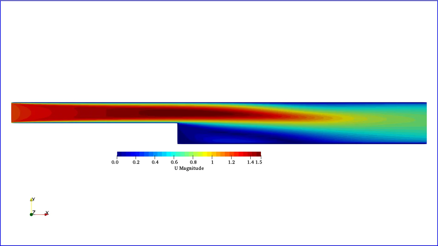
After simulation is converged, the velocity distribution is displayed below.
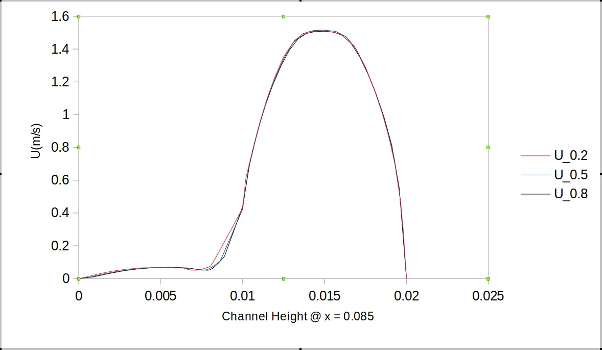
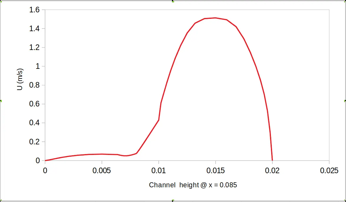
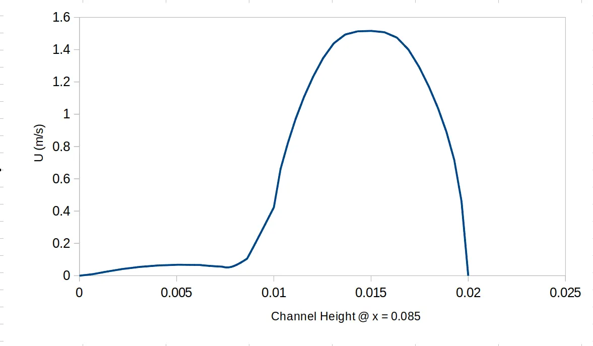
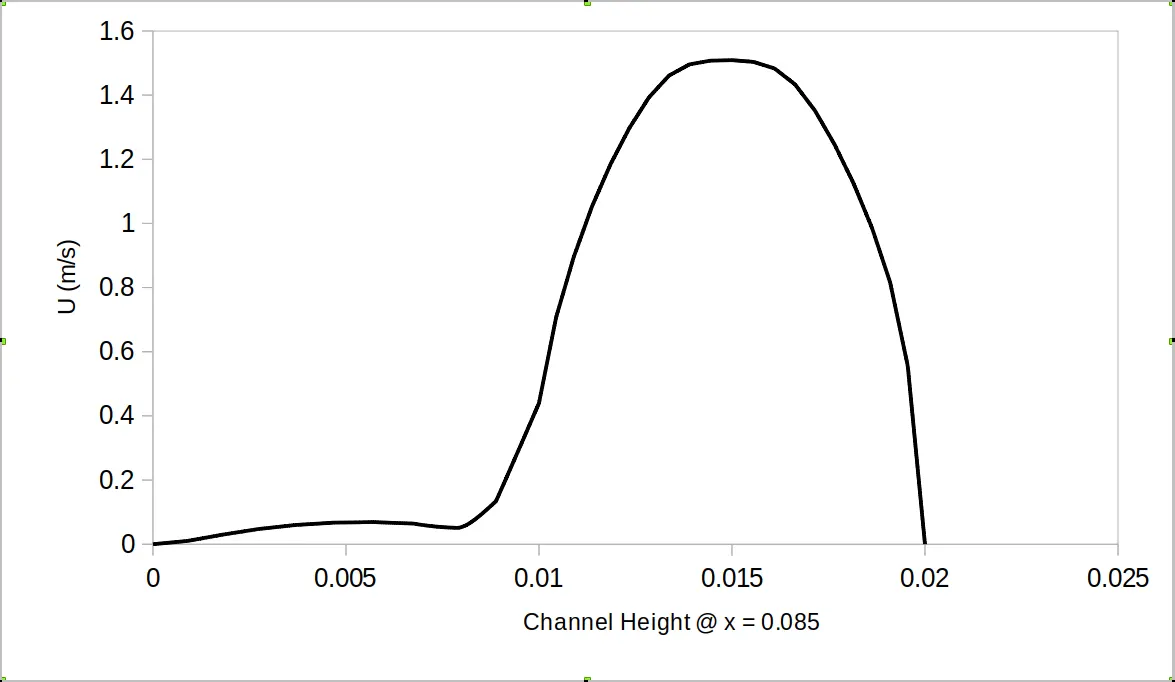
Data analysis of the velocity distribution at location x = 0.085 m was perform. the result was plotted and is displayed below.
Siimiar results were obtained for other grading factors and the mesh, the contour and the plots are displayed below.
Grading factor = 0.5
Grading factor = 0.8
Comparing Results for Different Grading Factors
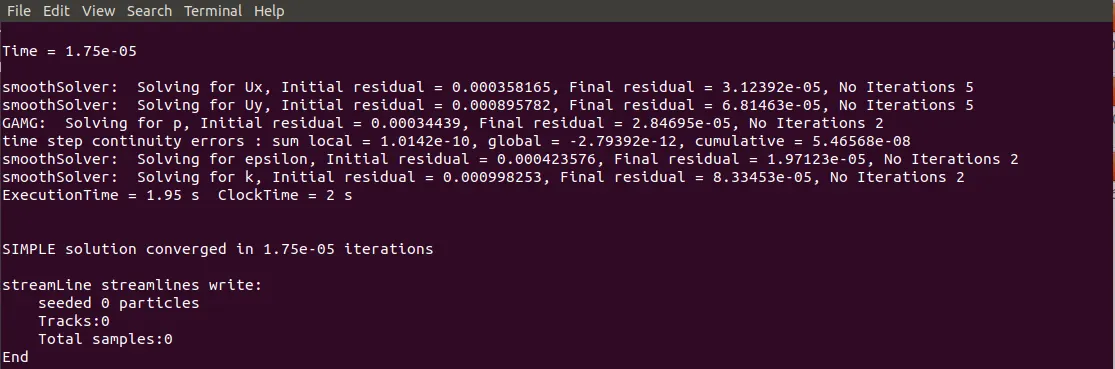
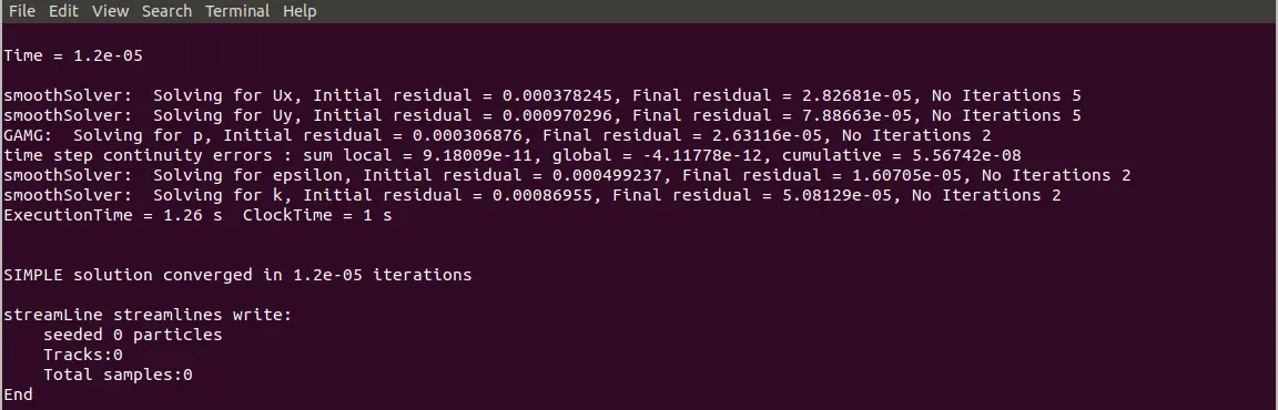
For this project, grading does not seem to have an effect as shown in the plot below. The plots lie on top of one another almost perfectly. The only difference is the time taken for the simulations to converge. The Table below depicts this. As Observed, grading factor = 0.2 took longest to converge. The reason could be due to a number of things such as skewness, aspect ratio, etc.
Perhaps the take away would be to apply moderate grading to allow for faster convergence.
| Grading Factor | 0.2 | 0.5 | 0.8 |
| Simulation Time | `2.34e^-5` | `1.75e^-5` | `1.2e^-5` |