Week 12 - Symmetry vs Wedge vs HP equation
Objective
This project is the continuation of the previous project on simulation of incompressible flow in a circular pipe using as piece of the geometry as the computation domain. The previous project made use of wedge boundary conditions on the wedge patch as shown in the image below.
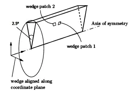
The present project's objective is to change wedge boundary conditions to symmetry boundary conditions. Specifically, we aim to
- run simulation for `theta = 10 , 25, 45` using symmetry BC
- compare results with those of previous projects and Hagen-Poiseuille analytical results
Theory
Symmetry BC
The symmetry boundary condition defines a mirror face/surface. It is only used if the physical object or geometry and the expected flow field pattern of the developed solution are mirrored along that surface. This boundary condition essentially allows the domain to be halved, reducing the time to achieve a solution.
In detail, the symmetry condition applies the following constraints on the flow variables:
- The fluxes across the symmetry are zero.
- The normal components of all variables are set to zero.
It can be applied to both planar or non-planar faces/surfaces on the domain boundaries.
Symmetry BC is not advised for axisymmetric or periodic flow cases. Wedge or periodic boundary conditions are better suitable for those cases.
Wedge BC
The wedge boundary condition is used to define an axisymmetric situation. The model and flow must be axisymmetric along a central line such that all physical variables of the flow have the same value and distribution at a given radius for all angles.
This boundary condition is specified by two planes that are selected on separate sides of the domain (referred to as front and back) on surfaces running along the axis. Wedge BC works for 2D simulations only.
Difference Between Wedge and Symmetry BCs
| Wedge | Symmetry |
| Applies the Navier-Stokes equations in cylindrical coordinates | Applies the Navier-Stokes equations in cartesian coordinates |
| Allows for the rotational flow around the axis | Does not allows for the rotational flow around the axis |
| The fluxes and normal components are not assumed as zero. | The fluxes and normal components are assumed as zero. |
Numerical Simulation
Numerical simulations were performed for a wedge of the cylindrical domain but using symmetry BCs instead of wedge. The simulation was carried out for wedge angles, `theta = 10, 25, 45` cases.
blockMeshDict generation
To set up the cases, the octave script along with the modular functions from the previous project was reused here (with some modifications) to generate the blockMeshDict. They are displayed below.
function foamHeader(objectName, conversion)
  foamHead = fopen('blockMeshDict', 'w');
  fprintf(foamHead, '%s\n', '/*--------------------------------*- C++ -*----------------------------------*\');
  fprintf(foamHead, '%s\n', '  =========                 |');
  fprintf(foamHead, '%s\n', '  \\      /  F ield         | OpenFOAM: The Open Source CFD Toolbox');
  fprintf(foamHead, '%s\n', '   \\    /   O peration     | Website:  https://openfoam.org');
  fprintf(foamHead, '%s\n', '    \\  /    A nd           | Version:  7');
  fprintf(foamHead, '%s\n', '     \\/     M anipulation  |');
  fprintf(foamHead, '%s\n', '\*---------------------------------------------------------------------------*/');
  fprintf(foamHead, '%s\n', 'FoamFile');
  fprintf(foamHead, '%s\n', '{');
  fprintf(foamHead, '%s\n', '    version     2.0;');
  fprintf(foamHead, '%s\n', '    format      ascii;');
  fprintf(foamHead, '%s\n', '    class       dictionary;');
  fprintf(foamHead, '%s %s %s\n', '    object     ', objectName, ';');
  fprintf(foamHead, '%s\n', '}');
  fprintf(foamHead, '%s\n\n', '// * * * * * * * * * * * * * * * * * * * * * * * * * * * * * * * * * * * * * //');
  fprintf(foamHead, '%s %d %s\n\n', 'convertToMeters ', conversion, ';');
  fclose(foamHead);
 end
function foamVertices(diameter, theta, length)
radius = diameter/2;
foamVertex = fopen('blockMeshDict', 'a');
fprintf(foamVertex, '%s\n', 'vertices');
fprintf(foamVertex, '%s\n', '(');
fprintf(foamVertex, '%s\n', ' (0 0 0) //0');
fprintf(foamVertex, '%s %f %f %s\n', ' (0', radius*cosd(theta/2), -radius*sind(theta/2),') //1');
fprintf(foamVertex, '%s %f %f %s\n', ' (0', radius*cosd(theta/2), radius*sind(theta/2),') //2');
fprintf(foamVertex, '%s%f %s\n', ' (',length, ' 0 0) //3');
fprintf(foamVertex, '%s%f %f %f%s\n', ' (',length, radius*cosd(theta/2), -radius*sind(theta/2),') //4');
fprintf(foamVertex, '%s%f %f %f%s\n', ' (',length, radius*cosd(theta/2), radius*sind(theta/2),') //5');
fprintf(foamVertex, '%s\n\n', ');');
fclose(foamVertex);
endfunction foamBlocks(grids, gradings);
foamBlock = fopen('blockMeshDict', 'a');
fprintf(foamBlock, '%s\n', 'blocks');
fprintf(foamBlock, '%s\n', '(');
fprintf(foamBlock, '%s %s %s %s \n', ' hex (0 1 2 0 3 4 5 3)', grids, 'simpleGrading', gradings);
fprintf(foamBlock, '%s\n\n', ');');
fclose(foamBlock);
endfunction foamEdges(edge_1, edge_2);
foamEdge = fopen('blockMeshDict', 'a');
fprintf(foamEdge, '%s\n', 'edges');
fprintf(foamEdge, '%s\n', '(');
fprintf(foamEdge, '%s %s\n', ' arc 1 2', edge_1);
fprintf(foamEdge, '%s %s\n', ' arc 4 5', edge_2);
fprintf(foamEdge, '%s\n\n', ');');
fclose(foamEdge);
endfunction foamBoundaries(b_names, b_types, b_faces)
foamBoundary = fopen('blockMeshDict', 'a');
fprintf(foamBoundary, '%s\n', 'boundary');
fprintf(foamBoundary, '%s\n', '(');
for i = 1:length(b_names)
fprintf(foamBoundary, '%s%s\n', ' ', b_names{i,1});
fprintf(foamBoundary, '%s\n', ' {');
fprintf(foamBoundary, '%s %s%s\n', ' type', b_types{i,1}, ';');
fprintf(foamBoundary, '%s\n', ' faces');
fprintf(foamBoundary, '%s\n', ' (');
fprintf(foamBoundary, '%s%s\n', ' ', b_faces{i,1});
fprintf(foamBoundary, '%s\n', ' );');
fprintf(foamBoundary, '%s\n', ' }');
end
fprintf(foamBoundary, '%s\n\n', ');');
fprintf(foamBoundary, '%s\n', 'mergePatchPairs');
fprintf(foamBoundary, '%s\n', '(');
fprintf(foamBoundary, '%s\n\n', ');');
fprintf(foamBoundary, '%s\n', '// ************************************************************************* //');
fclose(foamBoundary)
endclear all; close all; clc;
%inputs
diameter = 10; %mm
theta = 45; %degrees
length = 159; %mm
grids = '(50 1 100)';
gradings = '(0.1 1 10)';
edge_1 = '(0 5 0)';
edge_2 = '(159 5 0)';
b_names = {"inlet"; "outlet"; "wall"; "axis"; "front"; "back"};
b_faces = {"(1 0 0 2)"; "(5 3 3 4)"; "(2 5 4 1)"; "(0 3 3 0)"; "(0 3 5 2)"; "(0 1 4 3)"};
b_types = {"patch"; "patch"; "wall"; "empty"; "symmetry"; "symmetry"};
foamHeader('blockMeshDict', 0.001);
foamVertices(diameter, theta, length);
foamBlocks(grids, gradings);
foamEdges(edge_1, edge_2);
foamBoundaries(b_names, b_types, b_faces);
The output file for `theta=45` is displayed below.
/*--------------------------------*- C++ -*----------------------------------*\
  =========                 |
  \\      /  F ield         | OpenFOAM: The Open Source CFD Toolbox
   \\    /   O peration     | Website:  https://openfoam.org
    \\  /    A nd           | Version:  7
     \\/     M anipulation  |
\*---------------------------------------------------------------------------*/
FoamFile
{
    version     2.0;
    format      ascii;
    class       dictionary;
    object      blockMeshDict ;
}
// * * * * * * * * * * * * * * * * * * * * * * * * * * * * * * * * * * * * * //

convertToMeters  0.001 ;

vertices
(
    (0 0 0)              //0
    (0 4.619398 -1.913417 )              //1
    (0 4.619398 1.913417 )              //2
    (159.000000  0 0)              //3
    (159.000000 4.619398 -1.913417)              //4
    (159.000000 4.619398 1.913417)              //5
);

blocks
(
    hex (0 1 2 0 3 4 5 3) (50 1 100) simpleGrading (0.1 1 10)
);

edges
(
    arc 1 2 (0 5 0)
    arc 4 5 (159 5 0)
);

boundary
(
    inlet
    {
        type patch;
        faces
        (
            (1 0 0 2)
        );
    }
    outlet
    {
        type patch;
        faces
        (
            (5 3 3 4)
        );
    }
    wall
    {
        type wall;
        faces
        (
            (2 5 4 1)
        );
    }
    axis
    {
        type empty;
        faces
        (
            (0 3 3 0)
        );
    }
    front
    {
        type symmetry;
        faces
        (
            (0 3 5 2)
        );
    }
    back
    {
        type symmetry;
        faces
        (
            (0 1 4 3)
        );
    }
);

mergePatchPairs
(
);

// ************************************************************************* //
Initial & Boundary Conditions and controlDict
The files for initial and boundary conditions as well as the controlDict for the `theta = 45` case are displayed below. They are similar to those of the previous project except for the boundary conditions that were changed from wedge to symmetry.
/*--------------------------------*- C++ -*----------------------------------*\
  =========                 |
  \\      /  F ield         | OpenFOAM: The Open Source CFD Toolbox
   \\    /   O peration     | Website:  https://openfoam.org
    \\  /    A nd           | Version:  7
     \\/     M anipulation  |
\*---------------------------------------------------------------------------*/
FoamFile
{
    version     2.0;
    format      ascii;
    class       volScalarField;
    object      p;
}
// * * * * * * * * * * * * * * * * * * * * * * * * * * * * * * * * * * * * * //

dimensions      [0 2 -2 0 0 0 0];

internalField   uniform 0;

boundaryField
{
    inlet
    {
        type            zeroGradient;
    }

    outlet
    {
        type            fixedValue;
        value           uniform 0.7815;
    }

    wall
    {
        type            zeroGradient;
    }

    axis
    {
        type            empty;
    }

    front
    {
        type            symmetry;
    }

    back
    {
        type            symmetry;
    }
}

// ************************************************************************* //
/*--------------------------------*- C++ -*----------------------------------*\
========= |
\\ / F ield | OpenFOAM: The Open Source CFD Toolbox
\\ / O peration | Website: https://openfoam.org
\\ / A nd | Version: 7
\\/ M anipulation |
\*---------------------------------------------------------------------------*/
FoamFile
{
version 2.0;
format ascii;
class volVectorField;
object U;
}
// * * * * * * * * * * * * * * * * * * * * * * * * * * * * * * * * * * * * * //
dimensions [0 1 -1 0 0 0 0];
internalField uniform (0.48 0 0);
boundaryField
{
inlet
{
type fixedValue;
value uniform (0.48 0 0);
}
outlet
{
type inletOutlet;
inletValue uniform (0.48 0 0);
value uniform (0.48 0 0);
}
wall
{
type fixedValue;
value uniform (0 0 0);
}
axis
{
type empty;
}
front
{
type symmetry;
}
back
{
type symmetry;
}
}
// ************************************************************************* ///*--------------------------------*- C++ -*----------------------------------*\
========= |
\\ / F ield | OpenFOAM: The Open Source CFD Toolbox
\\ / O peration | Website: https://openfoam.org
\\ / A nd | Version: 7
\\/ M anipulation |
\*---------------------------------------------------------------------------*/
FoamFile
{
version 2.0;
format ascii;
class dictionary;
location "system";
object controlDict;
}
// * * * * * * * * * * * * * * * * * * * * * * * * * * * * * * * * * * * * * //
application icoFoam;
startFrom startTime;
startTime 0;
stopAt endTime;
endTime 0.2;
deltaT 0.00005;
writeControl timeStep;
writeInterval 20;
purgeWrite 0;
writeFormat ascii;
writePrecision 6;
writeCompression off;
timeFormat general;
timePrecision 6;
runTimeModifiable true;
// ************************************************************************* //Results and Analysis
Mesh
The results of the mesh generation script for all the three cases are displayed below. Apart from the fact that the wedge angles are larger than for the previous case, the distributions are the same.
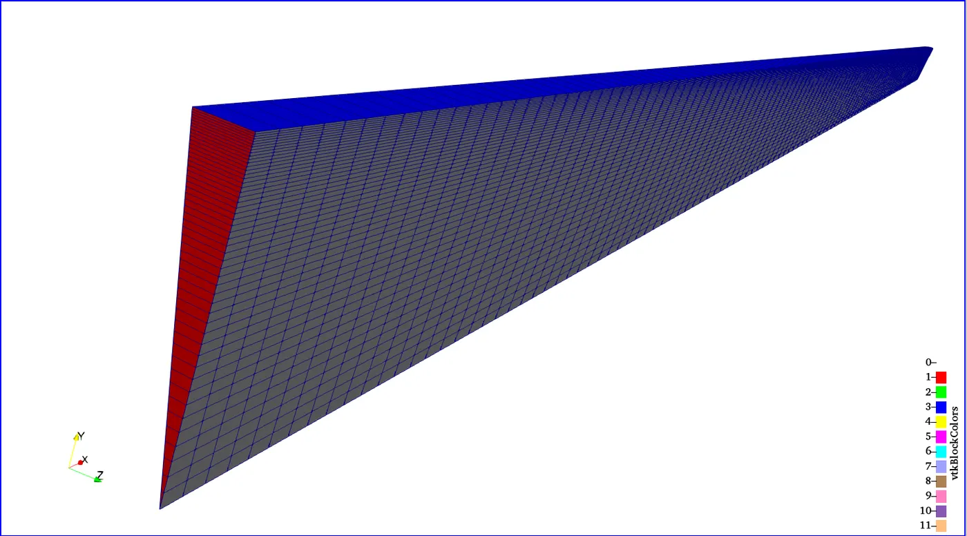
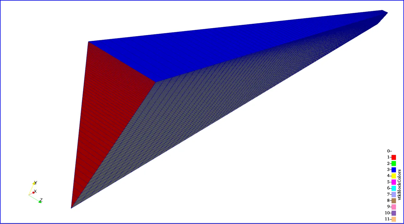
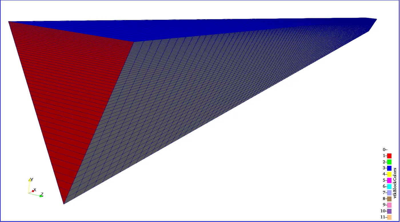
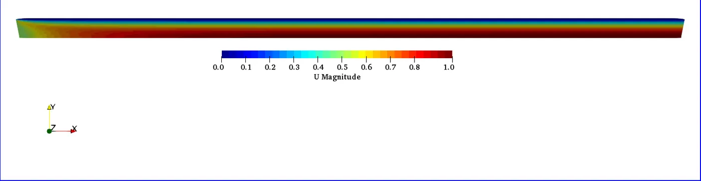
The velocity distribution in the domain are displayed below for `theta = 10, 25, 45` respectively. They are equally similar to those from the previous project.


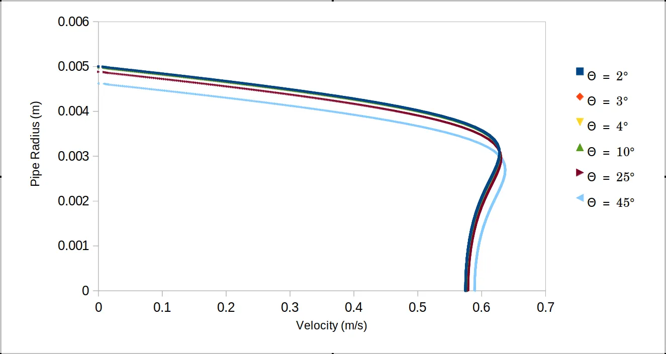
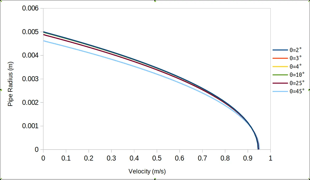
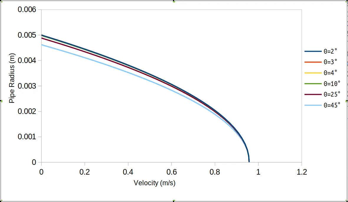
Results of the three cases were compared with those from previous project. Plots of velocity profile at locations `x = 0.005, 0.0795, 0.155` were made for all the cases. And they are displayed below.
From the plots below on can observe the similarity in the profiles for all six wedge angles. However, the first three wedge angles, `theta = 2, 3, 4` all lay on top of each other. These are the profiles from using the wedge boundary conditions and goes to show the accuracy of results for using this BC for this type of flow(2D axisymmetric flow). Others that are off are from using the symmetry which is an unsuitable BC for this type of flow. Another observaton from the profile plot is that for the `theta = 25, 45`, the domain radius is smaller than the geometry's. This would explain why velocity for `theta=45` is closer to is higer than the rest.
Comparing Symmetry vs Wedge vs Hagen-Poiseuille
The table below compares the output maximum velocity from both BCs to that from the Hagen-Poiseuille analytical output. As observed, they are all `le 1%`. Relative error for `theta = 45` seems the closest to Hagen-Poiseuile value. This is probably due to the reduction in the radius of the pipe domain modelled thus altering the fluid dynamics. While the cases with wedge BCs are consistent, the ones with the symmetry BCs are not. Wedge BC is thus more suitable for this type of flow. Also, the fact that the wedge angles for the symmetry BC cases are very large might also be a reason.
| Case | Boundary Condition | `u_("max","simulated")` | `u_("max","HP")` | Relative Error |
| 2 | Wedge | 0.957415 | 0.9600 | 0.269% |
| 3 | Wedge | 0.957417 | 0.9600 | 0.269% |
| 4 | Wedge | 0.95742 | 0.9600 | 0.269% |
| 10 | Symmetry | 0.957292 | 0.9600 | 0.282% |
| 25 | Symmetry | 0.957613 | 0.9600 | 0.249% |
| 45 | Symmetry | 0.957938 | 0.9600 | 0.215% |
In conclusion, the wedge BC is suitable for incompressible flow in a circular pipe because of its 2D axisymmetric nature. Also, large wedge angles are not advisable.