Week 8 - BlockMesh Drill down challenge
AIM: to simulate an incompressible-laminar-viscous flow through the backward facing step geometry. and we have to perform grading factor test and also we have to capture the results how the flow is going to change if we change some of the parameters
OBJECTIVES OF THE PROJECT:
- Specify the boundary mesh and create the right meshing for the structure.
- Define the initial conditions for pressure and velocity of the flow.
- Run the simulation for different values of mesh grading factor.
- Evaluate the velocity profile at 0.085m from the inlet.
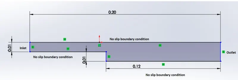
PROCEDURE TO CREATE THE GEOMETY OF THE GIVEN SPECIFIACATIONS IN THE PROBLEM:
- first create the blocks using the geometry given in the by joining the corresponding vertices of the block which you are created.
- crate the vertices as the given lengths in the geometry of the stepped bar.
- we have to edit the blockMeshDict fille to create the required geometry.
- as the required geometry is created we can go now and can apply the boundary conditions that is velocity and the pressure .
- for giving the boundary conditions we have to open the pressure and velocity files which are present in the zero folder.
- by using the gedit command we can edit the velocity and the pressure file where we acn apply the boundary conditions
- velocity at the inlet is 1 m/s uniform
- pressure at the inlet is zero gradient
- velocity at outlet id zero gradient
- pressure at outlet is 0.
- velocity at the topwalls , bottom walls , and the extra wall at bottom is maintained at no slip condition.
- and pressure at topwalls, bottom walls, extra wall at bottom maintained at zero gradient.
- and velocity at front and back walls kept as empty.
- and pressure at the front and back walls kept as empty.
- after applying the boundary conditions we going to simulate the file using the icofoam solver and then we can see the simulation on the screen,
- if the simulation start to blownup we have to reduce the courat number to less than 0.5.
- then again we have to run the solver and see the simulation by using the parafoam command.
- if we get the desired results we can get the velocity profile and we can get the other results and the results are tabulated.
EXPLANATION
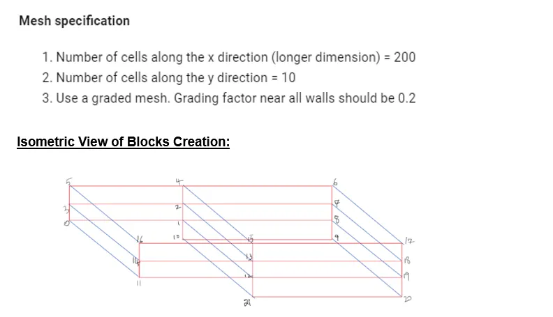
- the name of the vertices are different from the vertices name given in the figure we can give any name to the vertices as wish . but during the connection of the vertices we have to take care if we dont do that our geometry is going to change.
- first we are simulating with grading factor of the 1 means the mesh is not finer at the junctions so we cant find the solution better .
- we can fine the mesh using the blockmeshdict file in which we have to gave the maximum or minimum value of the end cell compared to the starting call
- GRADING FACTOR, G.F = size of end cell / size of starting cell.
- (0.1 1 1 ) the size of end cell is 0.1 times smaller than starting cell.
- (10 1 1) the size of end cell is 10 times bigger than starting cell.
how to run simulation
- first open the tutorial folder in tutorial open the incompressible in you have to open the icofoam ten you have to copy the cavity folder to the run folder.
- then you have to edit the blockmeshdict file in which you have to change the parameters according to your geometry.
- you have to run the blockmesh inside the cavity folder only if not it will show the fatal error.
- then you have to setup the simulation and the numeriackl parmeters.
- the3n run the simulation.
BLOCK MESH DICT FILE:
/*--------------------------------*- C++ -*----------------------------------*\
  =========                 |
  \\      /  F ield         | OpenFOAM: The Open Source CFD Toolbox
   \\    /   O peration     | Website:  https://openfoam.org
    \\  /    A nd           | Version:  8
     \\/     M anipulation  |
\*---------------------------------------------------------------------------*/
FoamFile
{
    version     2.0;
    format      ascii;
    class       dictionary;
    object      blockMeshDict;
}
// * * * * * * * * * * * * * * * * * * * * * * * * * * * * * * * * * * * * * //

convertToMeters 1;

vertices
(
    (0     0       0)
    (0.08  0       0)
    (0.08  0.005   0)
    (0     0.005   0)
    (0.08  0.01    0)
    (0     0.01    0)
    (0.2   0.01    0)
    (0.2   0.005   0)
    (0.2   0       0)
    (0.2  -0.01    0)
    (0.08 -0.01    0)


    (0     0       0.006)
    (0.08  0       0.006)
    (0.08  0.005   0.006)
    (0     0.005   0.006)
    (0.08  0.01    0.006)
    (0     0.01    0.006)
    (0.2   0.01    0.006)
    (0.2   0.005   0.006)
    (0.2   0       0.006)
    (0.2  -0.01    0.006)
    (0.08 -0.01    0.006)

);

blocks
(
    hex (0 1 2 3 11 12 13 14)  (160 10 1) simpleGrading (1 1  1)
    hex (3 2 4 5 14 13 15 16)  (160 10 1) simpleGrading (1 1  1)
    hex (1 8 7 2 12 19 18 13)  (220 10 1) simpleGrading (1 1  1)
    hex (2 7 6 4 13 18 17 15)  (220 10 1) simpleGrading (1 1  1)
    hex (10 9 8 1 21 20 19 12) (220 20 1) simpleGrading (1 1  1)

);

edges
(
);

boundary
(
    inlet
    {
        type patch;
        faces
        (
         (5 3 14 16)
         (3 0 11 14)
        );
    }
    outlet
    {
        type patch;
        faces
        (
         (7 6 17 18)
         (8 7 18 19)
         (9 8 19 20)
        );
    }
    frontwalls
    {
        type empty;
        faces
        (
            (11 12 13 14)
            (14 13 15 16)
            (12 19 18 13)
            (13 18 17 15)
            (21 20 19 12)
        );
    }
    backwalls
    {
        type empty;
        faces
        (
            (0 3 2 1)
            (3 5 4 2)
            (1 2 7 8)
            (2 4 6 7)
            (10 1 8 9)

        );
    }
    topwalls
    {
        type wall;
        faces
        (
            (16 15 4 5)
            (15 17 6 4)
        );
    }
    bottomwalls
    {
        type wall;
        faces
        (
            (1 12 11 0)
            (10 9 20 21)
        );
    }
    extrawallatbottom
    {
        type walls;
        faces
        (
            (1 10 21 12)
        );
    }
);

mergePatchPairs
(
);
velocity boundary condition file
/*--------------------------------*- C++ -*----------------------------------*\
  =========                 |
  \\      /  F ield         | OpenFOAM: The Open Source CFD Toolbox
   \\    /   O peration     | Website:  https://openfoam.org
    \\  /    A nd           | Version:  8
     \\/     M anipulation  |
\*---------------------------------------------------------------------------*/
FoamFile
{
    version     2.0;
    format      ascii;
    class       volVectorField;
    object      U;
}
// * * * * * * * * * * * * * * * * * * * * * * * * * * * * * * * * * * * * * //

dimensions      [0 1 -1 0 0 0 0];

internalField   uniform (0 0 0);

boundaryField
{
    inlet
    {
        type            fixedValue;
        value           uniform (1 0 0);
    }
    outlet
    {
        type            zeroGradient;
    }

    topwalls
    {
        type            noSlip;
    }
    bottomwalls
    {
        type            noSlip;
    }

    extrawallatbottom
    {
        type            noSlip;
    }


    frontwalls
    {
        type            empty;
    }
    backwalls
    {
        type            empty;
    }
}

// ************************************************************************* //
pressure boundary condition file
/*--------------------------------*- C++ -*----------------------------------*\
  =========                 |
  \\      /  F ield         | OpenFOAM: The Open Source CFD Toolbox
   \\    /   O peration     | Website:  https://openfoam.org
    \\  /    A nd           | Version:  8
     \\/     M anipulation  |
\*---------------------------------------------------------------------------*/
FoamFile
{
    version     2.0;
    format      ascii;
    class       volScalarField;
    object      p;
}
// * * * * * * * * * * * * * * * * * * * * * * * * * * * * * * * * * * * * * //

dimensions      [0 2 -2 0 0 0 0];

internalField   uniform 0;

boundaryField
{
    inlet
    {
        type            zeroGradient;
    }
    outlet
    {
        type            fixedValue;
        value           uniform 0;
    }

    topwalls
    {
        type            zeroGradient;
    }
    bottomwalls
    {
        type            zeroGradient;
    }

    extrawallatbottom
    {
        type            zeroGradient;
    }


    frontwalls
    {
        type            empty;
    }
    backwalls
    {
        type            empty;
    }
}

// ************************************************************************* //
result:
the flow of fluid in the backward facing stepped geometry. with using the default grading factor
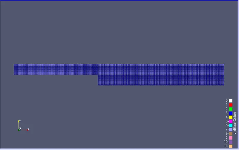
- this is the mesh created with using the DEFAULT grading factor 1
- we cant get the desired results if we use the default mesh so we have to create the mesh according to our geometry.
- the mesh has to be finer at the junctions so we can get the desired simulations.
VELOCITY SIMULATION USING THE DEFAULT GRADING FACTOR
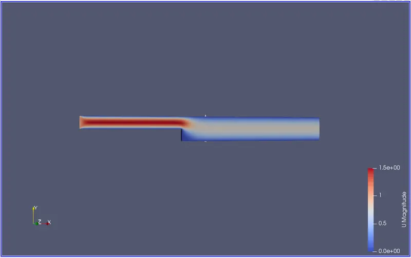
- this figure showing the velocity distribution along the flow area as we are not created mesh by mesh grading the simulation in not upto the mark.
- we can find the fluid flow at the end in re3d colour because od the mesh is not finer .
- the velocity near the bottom of the wall is nearly equal to the zero because of the viscosity and friction.
- as the velocity increases the dynamic pressure also increases and static pressure decreases.
- the velocity becomes constant after reaching the particualr length.
PRESSURE SIMULATION WITH DEFAULT GRADING FACTOR
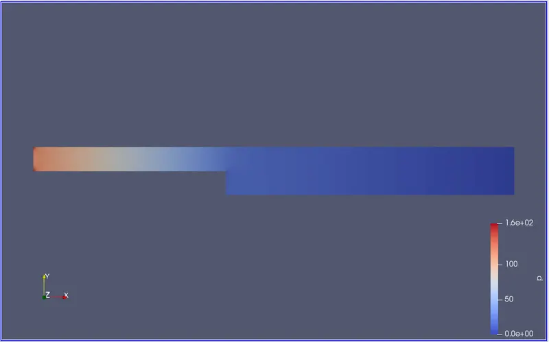
- this simulation shows how the pressure changes according to the length of the domain the initially pressure is at high.
- as it goes through with the length of the domain it will reduce and then pressure drop becomes linear.
VELOCITY PROFILE BEFORE GRADING FACTOR IS APPLIED
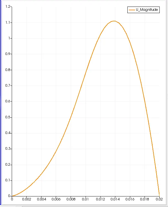
- this ids the velocity profile at the distance of the 0.085 meter
- it shows the how the velocity varies according to the length .
- as the length of the domain or length of pipe or the length backward-facing stepped geometry increases at particular point it attains a constant stage.
RESULTS AFTER GRADING FACTOR IS APPLIED

MESH AFTER GRADING FACTOR IS APPLIED
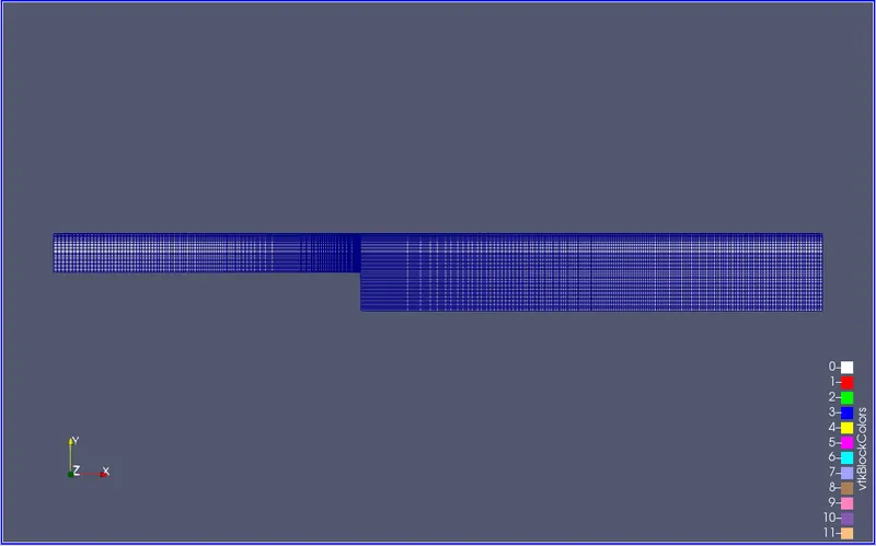
- this mesh is done through the grading factor at the area of the junction of the to get the results more accurate when we run the simulation.
- and the edges of the walls are also refined by using the mesh grading so at the dges we can get the stable solution.
- this mesh gives us more accurate results in the simulation if we compare it with the the mesh with default grading factor.
VELOCITY SIMULATION AFTER GRADING FACTOR IS APPLIED
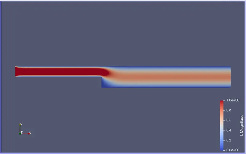
- this figure showing the simulation of the fow of the fluid in the stepped cross sectional area .
- when we compare it with a simulation of the default grid points it will differ in the results and accuracy .
- in default grid we cant see the simulation accurately but this simualation shows the results that are more desirable.
- in top and bottom faces we applies no slip condition so tha fluid near the top and bottom is stationary.
PRESSURE SIMULATION AFTER GRADING FACTOR IS APPLIED
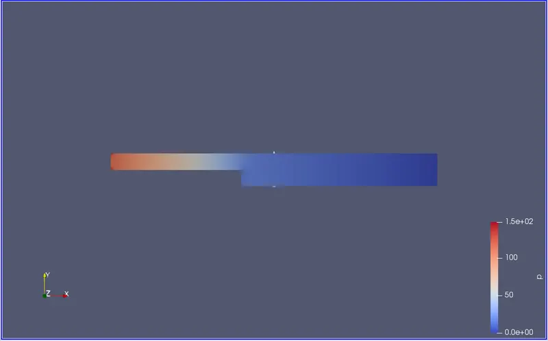
- as the length of the domain increases
- this simulation shows how the pressure changes according to the length of the domain the initially pressure is at high.
- as it goes through with the length of the domain it will reduce and then pressure drop becomes linear.
VELOCITY PROFILE AFTER GREDING FACTOR IS APPLIED
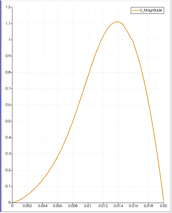
- this ids the velocity profile at the distance of the 0.085 meter
- it shows the how the velocity varies according to the length .
- as the length of the domain or length of pipe or the length backward-facing stepped geometry increases at particular point it attains a constant stage.