Week 8-3D Tetra Meshing Challenge
MODEL 1 (HOUSING)
OBJECTIVE
- To create 3D tetramesh by first creating 2D surface elements and then converting to 3D.
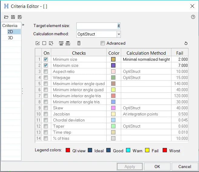
- Surface elements should have Minimum Size = 2 units, Target Size = 4 units and Maximum Size = 7 units.
- The Tet Collapse should be set as 0.15.
PROCEDURE
- The model is imported using the import geometry option.The solids are deleted, since it is easier to mesh on surfaces.
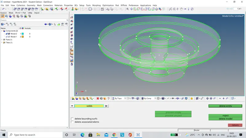
- Then the model is cleaned up manually for geometric irregularities and the fillets which are less than the minimum element size are defeatured.In the image below it can be seen that a mid line is created and the surfaces are trimmed by using it, thus defeaturing the surface which was failing for minimum element size.
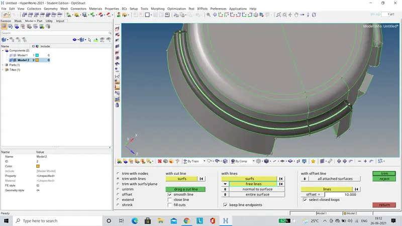
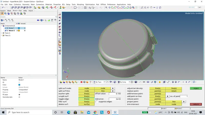
- In the below image, it can be seen that unwanted geometric lines are toggled.
- Before meshing the quality criteria is defined as shown below.
- Then using the automesh option, a surface mesh is created on the Housing and Hub components as shown below.The target element size is set to 4 units and the mesh type is set to trias.
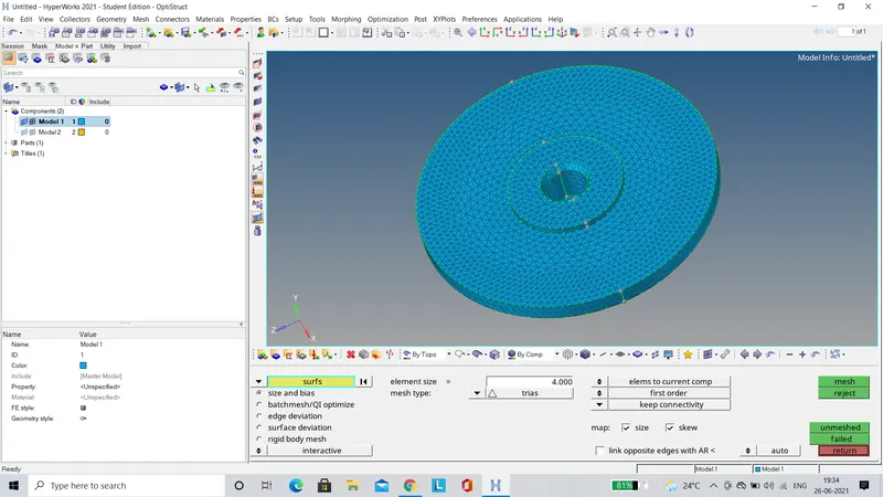
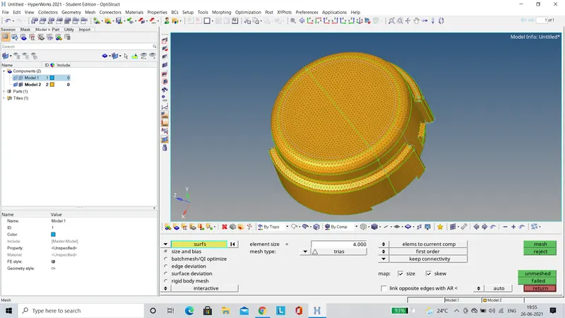
- After the surface mesh elements are created, they are validated for minimum and maximum element length failure.There were no elements failing for the Hub component, but the Housing had a few elements failing.
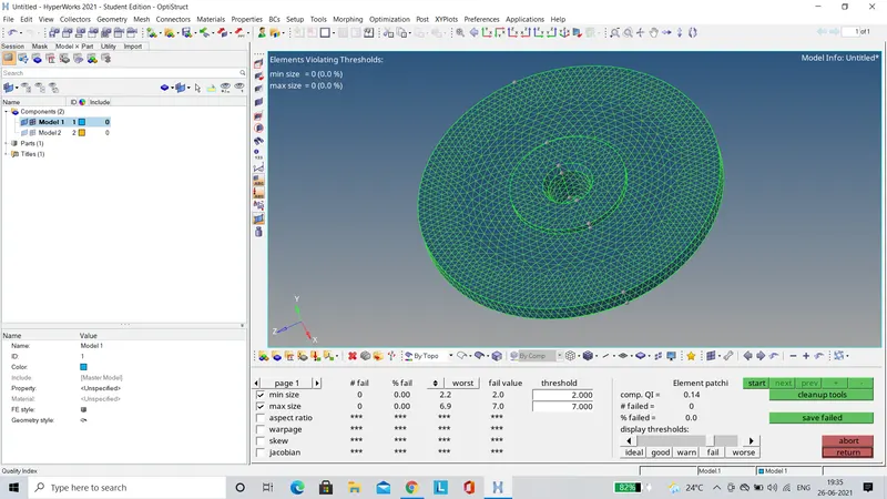
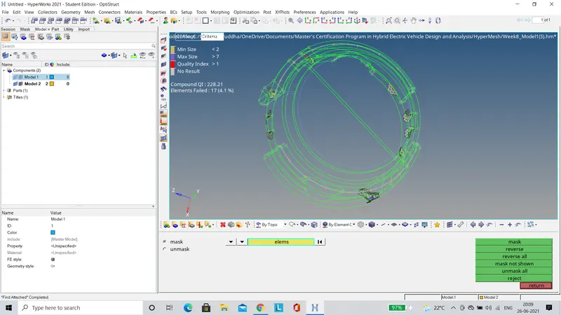
- The elements which were failing for minimum and maximum size were rectified using the translate tool as shown below.
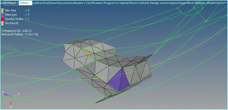
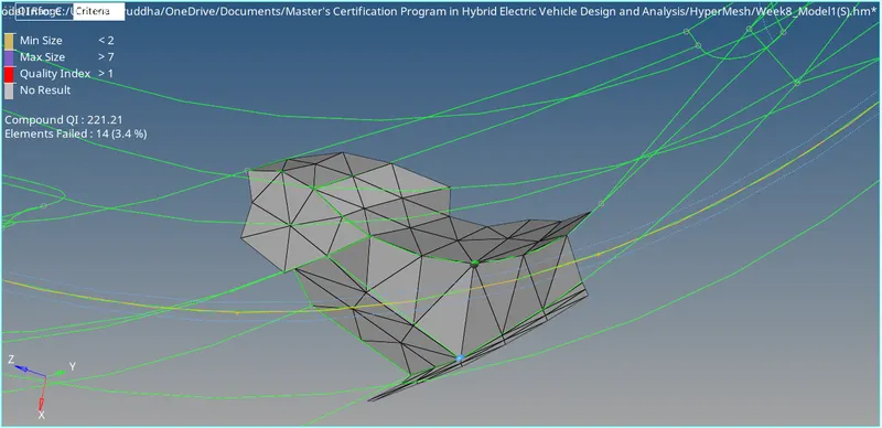
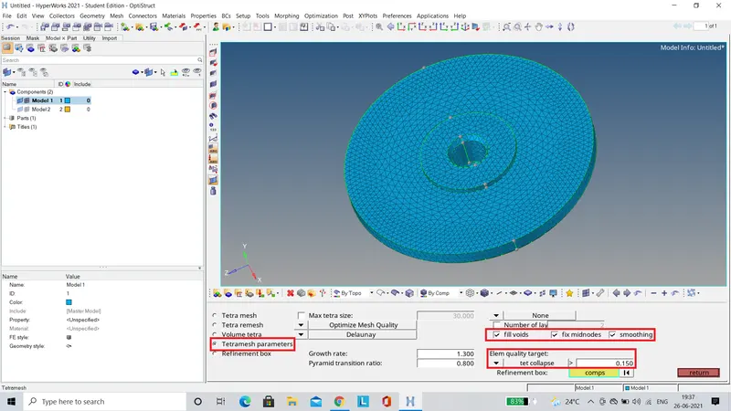
- Now the 2D surface elements are converted to 3D tetramesh.Before converting the tetramesh parameters are set as shown below.The tet collapse is set to 0.150.
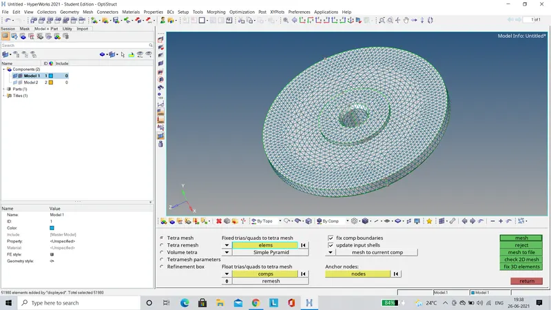
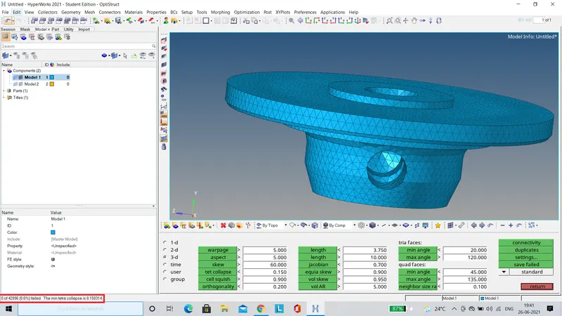
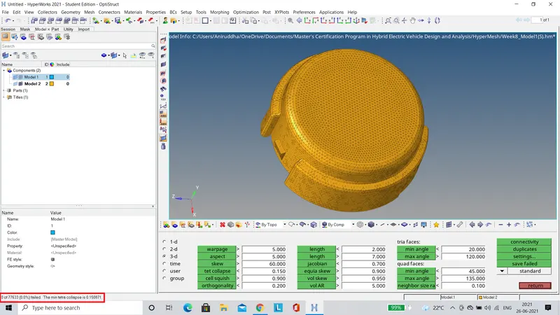
- Finally, the 3D tetramesh is validated for tet collapse.It can be seen below that there are no elements failing for tet collapse.
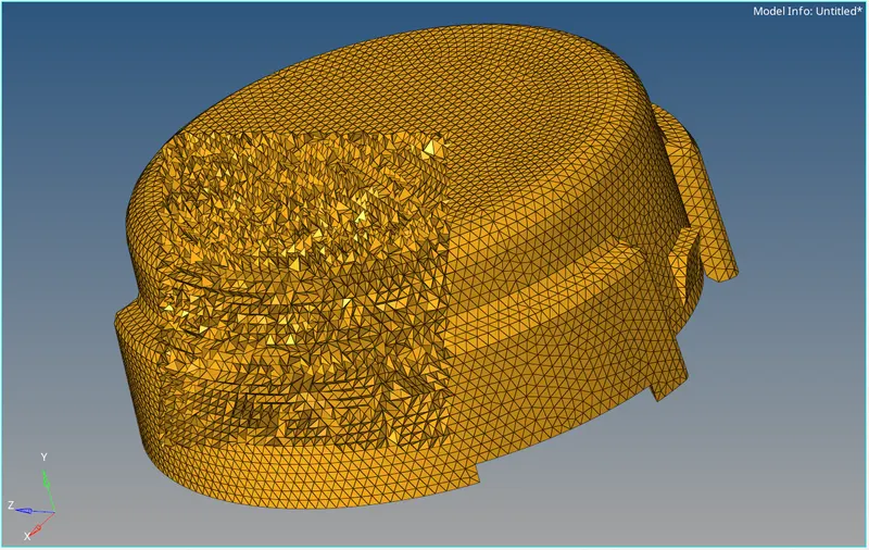
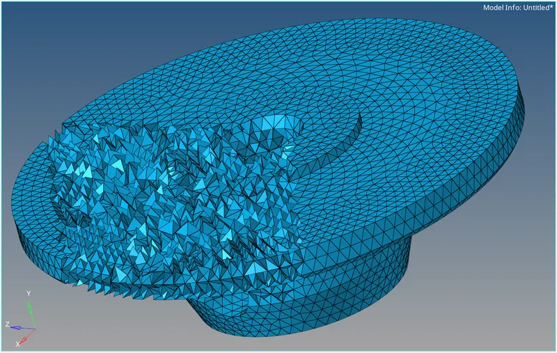
FINAL MODEL IMAGES (Few elements have been masked to visualise the 3D tetramesh)
MODEL 2
OBJECTIVE
- To create a 3D tetramesh using the Volume Tetra Mesh option on the given component.
- The target element size should be set as 3 and the tet collapse as 0.15.
PROCEDURE
- The component is imported using the Import Geometry option.
- The component is checked for any geometric deformities.
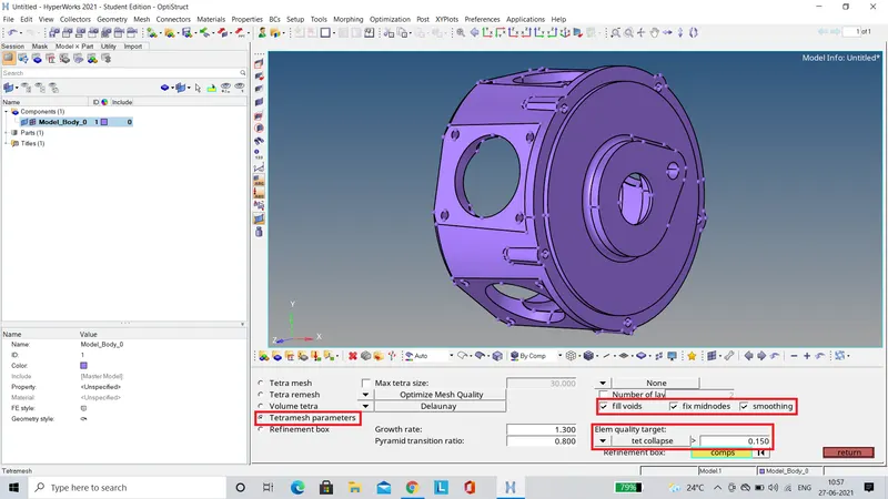
- From 3D menu, the tetramesh panel is selected.The tetramesh parameters are set as shown below.The tet collapse is set to 0.15.Also the checkboxes for 'fill voids', 'fix midnodes', and 'smoothing' are selected to avoid element failures.
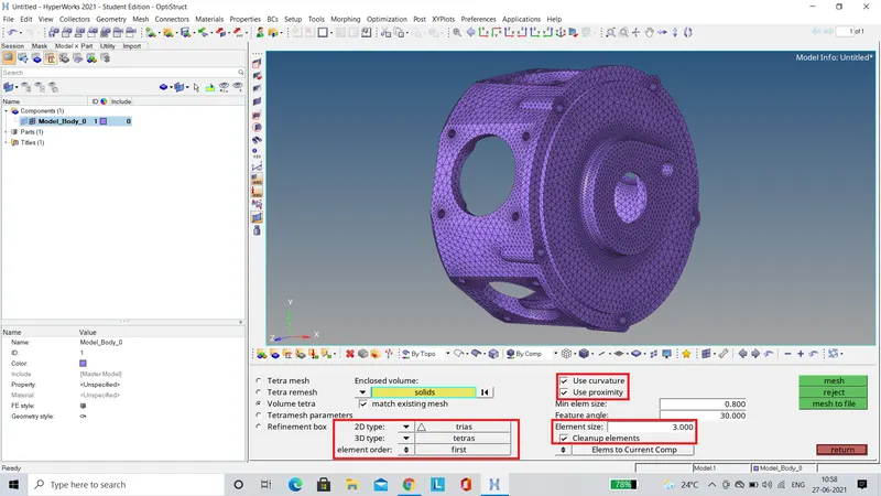
- Finally, using the Volume Tetra tool the component is meshed by setting the element size to 3 units.The 'Use curvature', 'Use proximity', and 'Cleanup elements' checkboxes are selected to ensure better mesh quality.
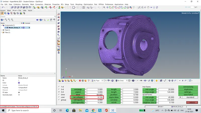
- After meshing, the component is validated for tet collapse using the check elems tool as shown below.There are no elements failing for tet collapse.
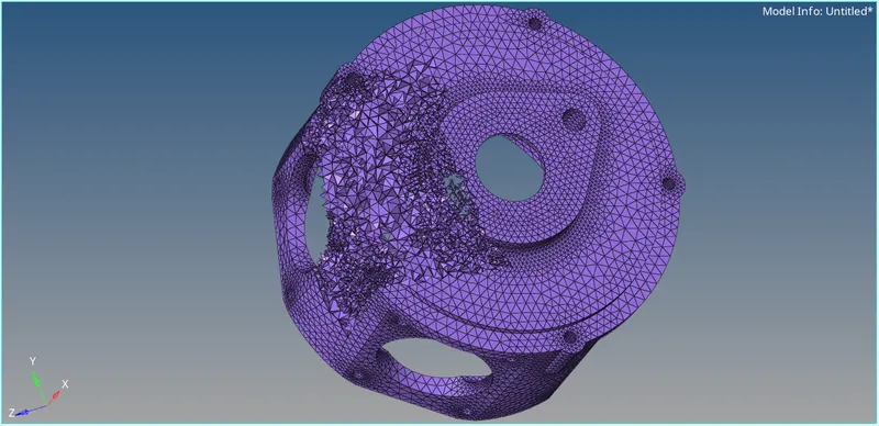
FINAL MODEL IMAGE (Few elements have been masked to visualise the 3D tetramesh)
MODEL 3
OBJECTIVE
- To create a 3D tetramesh using the Volume Tetra Mesh option on the given component.
- The target element size should be set as 4 and the tet collapse as 0.15.
PROCEDURE
- The component is imported using the Import Geometry option.
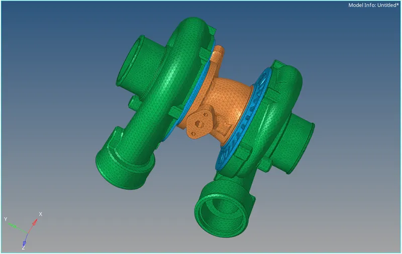
- In this case all the 5 components ie two Casings, two Impellers and a Cental Hub are seperately meshed.
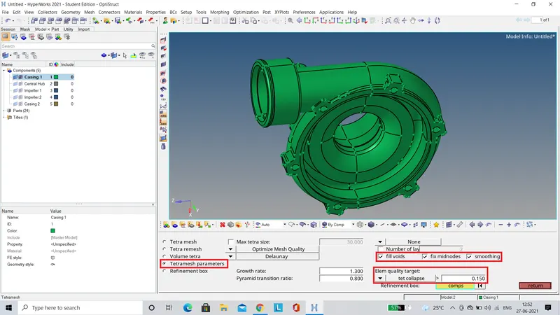
- From 3D menu, the tetramesh panel is selected.The tetramesh parameters are set as shown below.The tet collapse is set to 0.15.Also the checkboxes for 'fill voids', 'fix midnodes', and 'smoothing' are selected to avoid element failures.
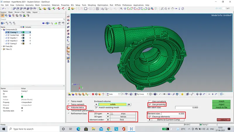
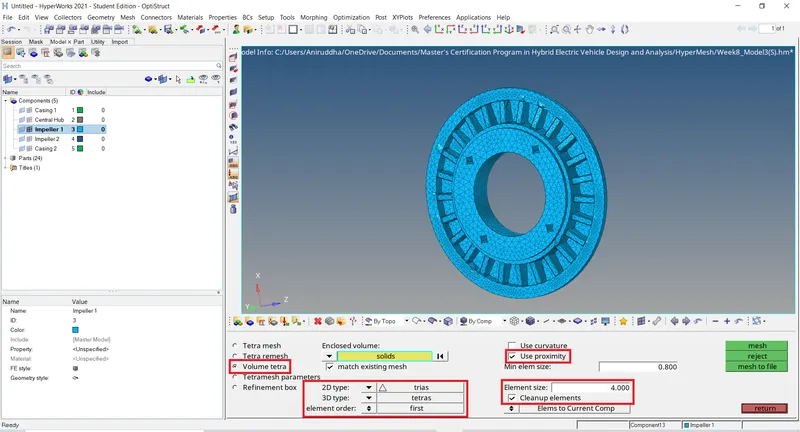
- Finally, using the Volume Tetra tool the component is meshed by setting the element size to 4 units.The 'Use proximity' and 'Cleanup elements' checkboxes are selected to ensure better mesh quality.
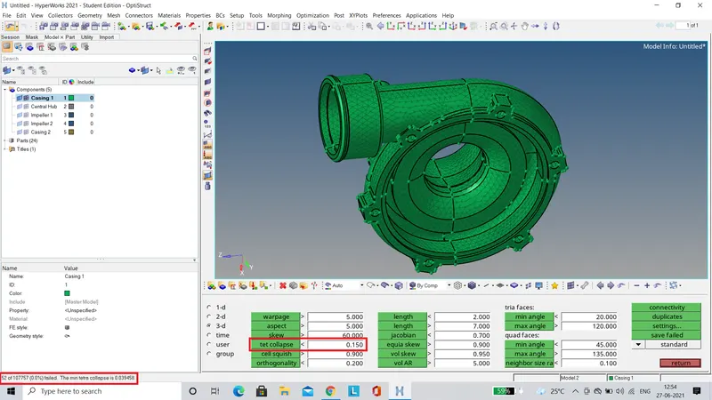
- After meshing, the 3D tetramesh is validated for tet collapse using the check elems tool, as shown below.
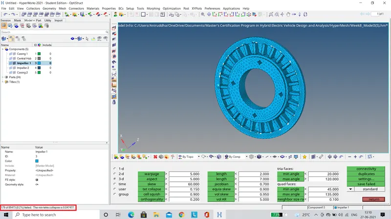
- To visualise the elements which are failing, 'save failed' option is selected in the check elems tool.Further in the mask tool the elems which failed are retrieved as shown below.
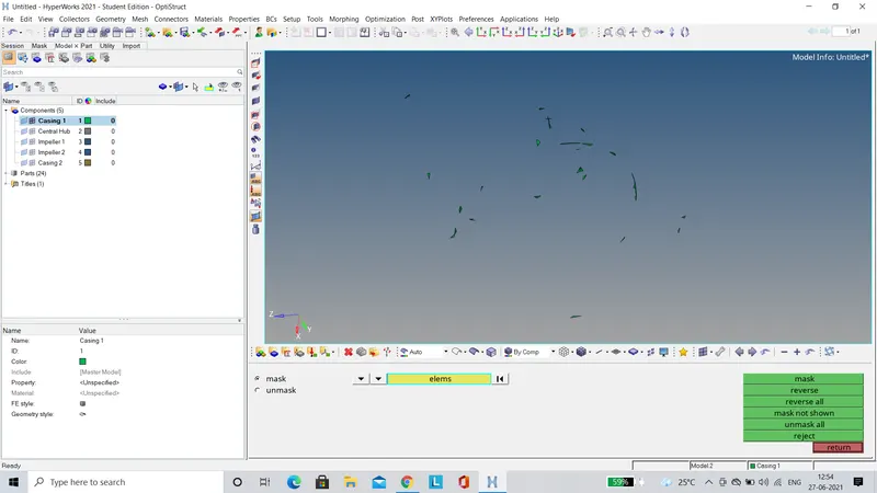
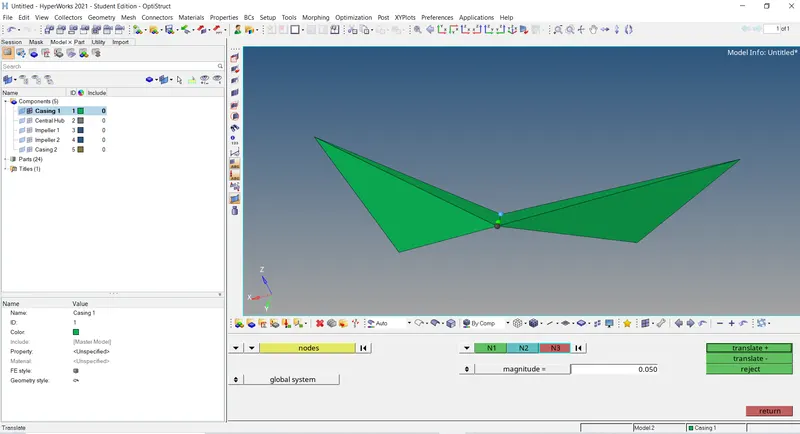
- The failed elements are rectified using the translate tool.The length of the joint is increased by 0.1 units to rectify the failure as shown below.
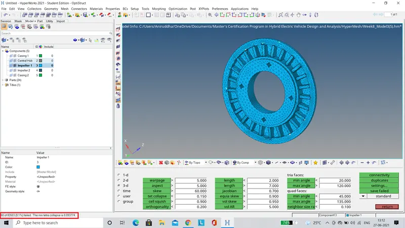
- The Tetra Remesh tool can also be used to rectify the element failures upto a certain extent.It can be seen below that after remeshing, the number of elements failing for tet collapse has reduced from 179 to 60 for the Impeller component.
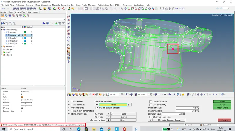
- While meshing the Central Hub component, an error occured since there was a penetration in the solid component as shown below.
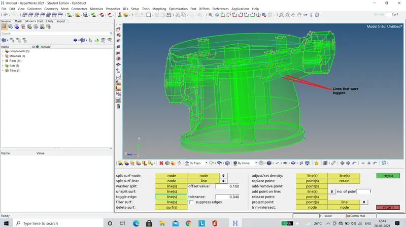
- In order to rectify this error, the geometric construction lines present at the penetration were toggled as shown below.
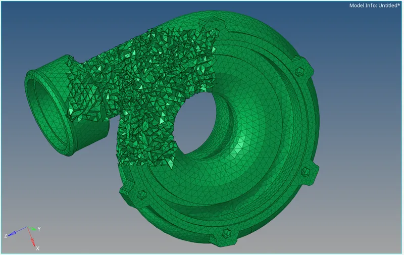
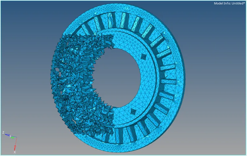
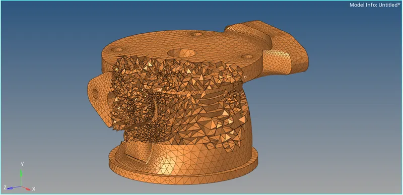
FINAL MODEL IMAGES (Few elements have been masked to visualise the 3D tetramesh)