Week 8-3D Tetra Meshing Challenge
Tetra meshing on different components of suspension system using hyperworks
Aim:- To perform 3D meshing or tetra meshing on components of suspension system by using hyperworks.
Given parameters:- Elements sizes: Min- 2mm, Target- 5mm, Max- 7mm
Tet collapse: 0.15
- Housing Model
- Model-2, Model-3 Create 3D tetra mesh with 6mm element size.
Software used :- Hyperworks student version 2020
Methodology :-
- Import CAD geometric model into hyperworks.
- Perform geometry clean-up and topology
- Deploying 3D mesh as per given quality parameters.
- Check for quality fail and eliminate them.
Theory :-
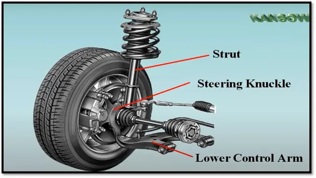
Suspension components :-
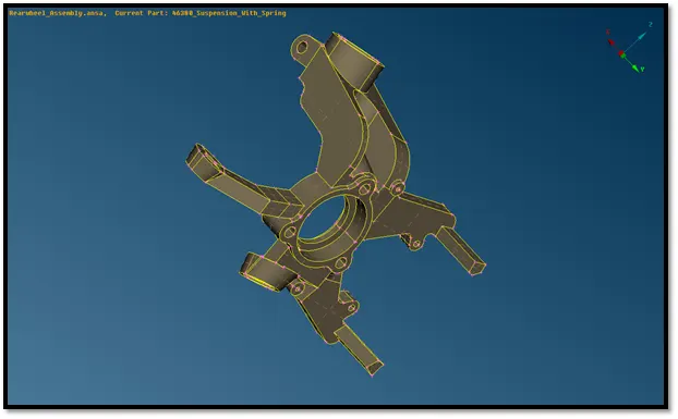
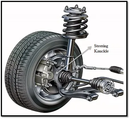
- Steering knuckles : Steering knuckles supports the wheel, brake and spring weight of vehicle. The spindle portion of steering knuckle supports wheel bearing and brake components and allows wheel to rotate on its bearings.
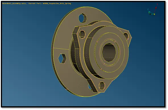
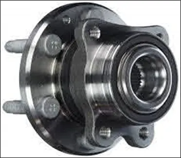
- Wheel hub :- Wheel hub contains wheel bearings which allows to rotate wheel freely with reduced friction. Wheel hub must provide a secure mounting surface for wheel and rim assembly.
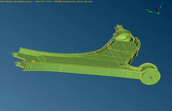
- Control arm :- A control arm holds the steering knuckle, bearing support, or axle housing in position as the wheel moves up and down. The outer end of a control arm has a ball joint. The inner end has bushings. A rear suspension control arm may have bushings on both ends.
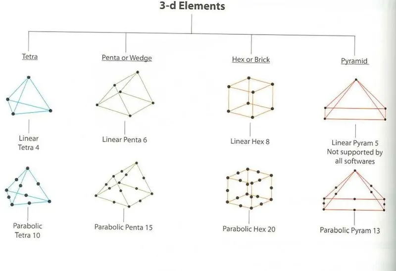
3D elements types :-
Tetra Meshing techniques :-
- Automatic mesh :- This approach is only limited to simple geometric CAD model and prerequisite is error free model. In this method user has to just select volume and software automatically carries out meshing as per selected element size and quality criteria. It is very quick and easy method for tetra meshing but it gives high number of nodes and element. Also there is no control on mesh flow lines and mesh pattern.
- 2D (Tria) to 3D (Tetra) Mesh :- This is most commonly used method. Quad or tria elements carried out on all over the outer surface of geometry, quad splits to trias and then converted to tetras.
Procedure :-
- Model 1 by (2D to 3D Mesh) :- For model 1 we have to first create 2D trias element all over its outer surface and then generate 3D or tetra elements in it. First we have to import geometry of given model which is housing component as shown in image below.
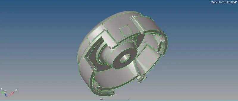
After that clean geometry by manually observing geometry of model. Observe the model in wireframe mode. If any red or yellow edge is present in model then there need to clean geometry but here no any such edges seen so we can move further to 2D meshing.
For 2D mesh we used Automesh option and generate 2D tria elements on all over the surface as shown in image below.

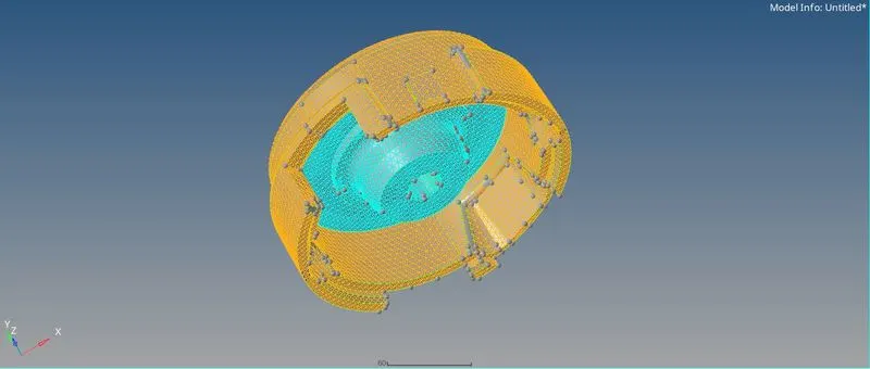
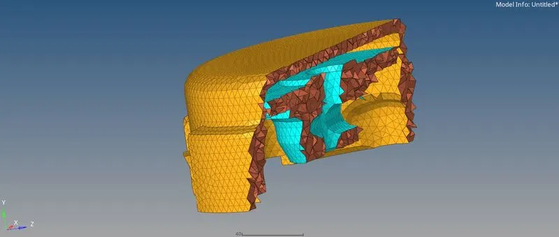
After creating 2D tria elements we can create tetra element inside it by using 3D > Tetramesh > Tetramesh > Select 2D elements > Mesh and it will generate tetra elements as shown in images below.
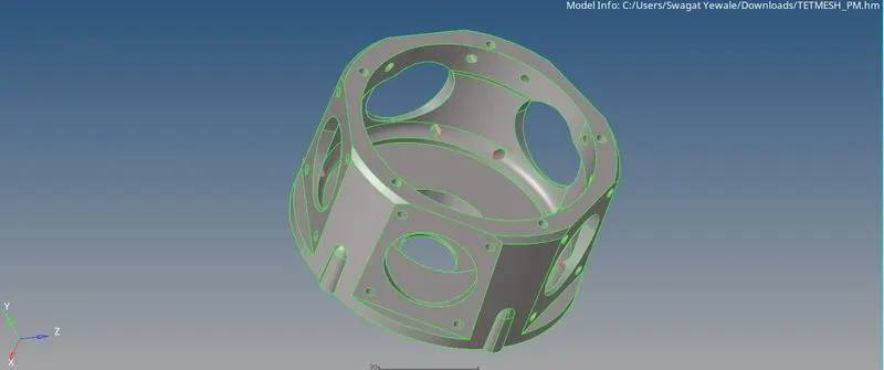
- Model 2 ( Volume meshing) :- For model 2 we are going to mesh by volume mesh type in that we are going to directly create tetra mesh without creating 2D mesh over outer surface. After importing CAD geometry we are going to perform geometry clean-up as shown in images below.

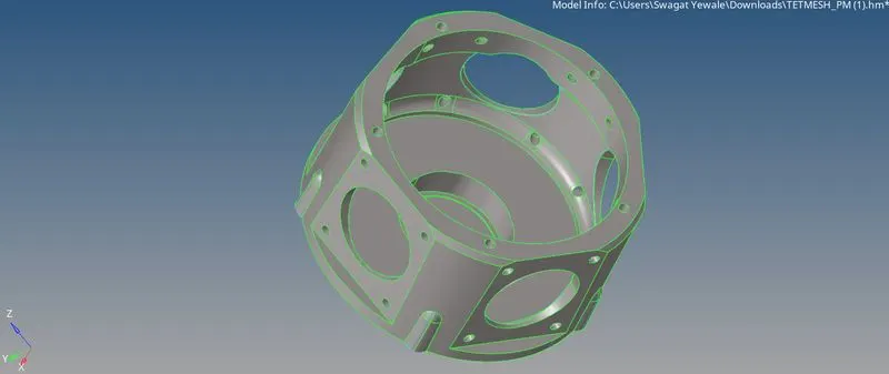
After that we going to generate 3 D elements by 3D > Tetramesh > Volume tetra > select surface > Mesh option. And Tetra elements are generated inside the surface as shown in images below.

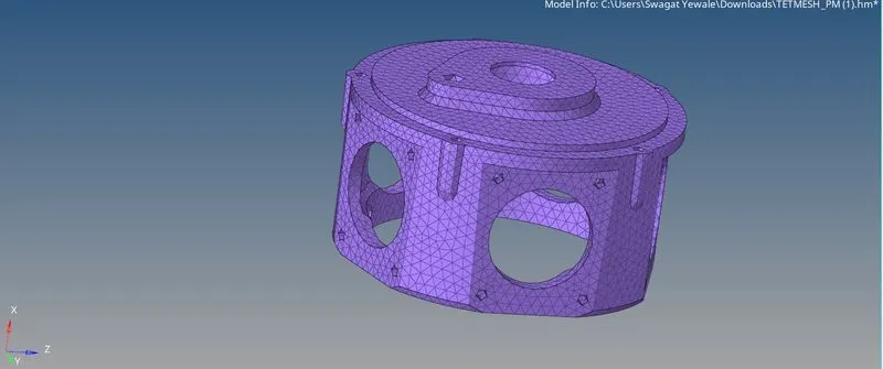
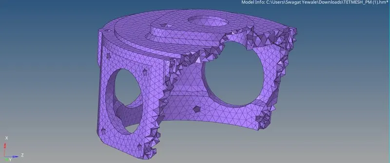
- Model 3 ( By using utility option ) :- for model 3 we can use mesh option under utility panel by this method we can defeature and tetra meshed model in one step due to this, this method is very easy and effective.
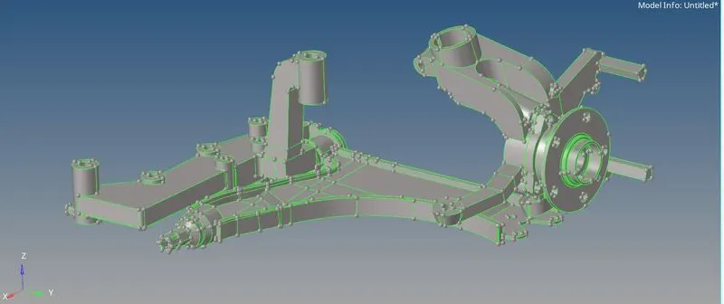
First, we have to import CAD geometry of model 3 which is suspension components. After importing we can see lot of geometric errors by viewing in shaded mode as shown in below image. We need to clean up all geometric errors before meshing by using quick edit menu.
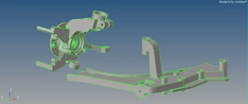
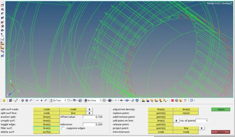
Lots of surfaces gets distorted during importing model we can manually fix all these errors by using filler surface.
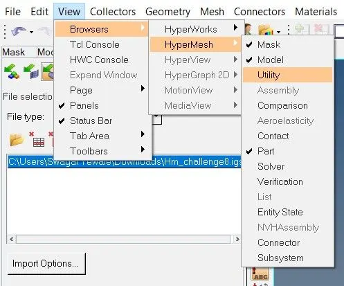
For meshing by this type we need to open view > Browsers > Hypermesh > Utility > Geo/Mesh > Quick tetra > select component > entre parameters > Mesh option it will mesh the component as well as defeature the geometry in one click as shown in below images.
Checking for tetra collapse and rectifying it.
Quality criteria in 3-D or tetra meshing :-
- Tetra collapse :- Tet collapse is one of the quality parameters, which will be checked while generating Tetra elements. It can be calculated by measuring the distance of a node from the opposite face, then each of the four values will be divided by the Square root of the opposite face’s area. The minimum of four resulting values is then normalized by dividing it by 1.24.
Generally tetra collapse can be calculated by the formula = Min of (h/√A) ÷ 1.24
In that formula, “h” represents the Height, between the Node (N1) and the opposite face of the Triangle. “A” represents the Area of Opposite Face (area of the Triangle).
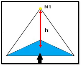
Fig. Tetra collapse
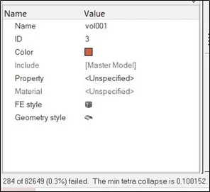
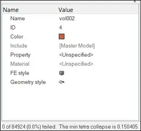
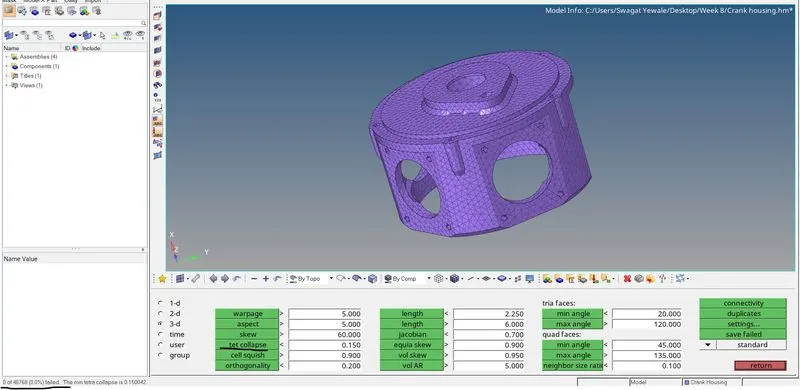
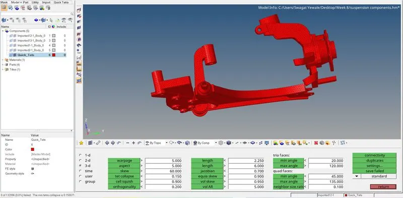
In this project quality criteria given for tet collapse is 0.15 there are 284, 138 and 259 off elements are generated for model 1, 2, and 3 respectively we can easily eliminate this by increasing the minimum node distance of off elements also we can eliminate this by masking only off elements and remeshing them by using 3D > Tetramesh > Tetraremesh > select off elements > Remesh option. As shown in below images.
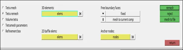
After remeshing we can check Tet collapse by using Tools > check element > 3D > Tet collapse option, it will shows number of off elements we need to remesh till 0 number of off elements remains.
Learning outcomes :-
- By using utility option for meshing is very easy and fast but it will defeature the geometry which is not proper for some geometry.
- 3D meshing is only done for components having thickness more than 5 mm.
- 2D to 3D meshing is the best option for tetra meshing because in that method we can defeature geometry manually and geometry capture is properly done.
- 3D meshing is done on casting and forming components.
Conclusion :- The housing component is meshed with 2D to 3D meshing type, crank housing is meshed with volume meshing and suspension components are meshed with utility option with 0% Tet collapse elements and model is ready for further post-processing and solving.