Week 8-3D Tetra Meshing Challenge
Model-1
- Objective:
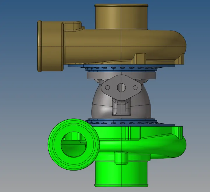
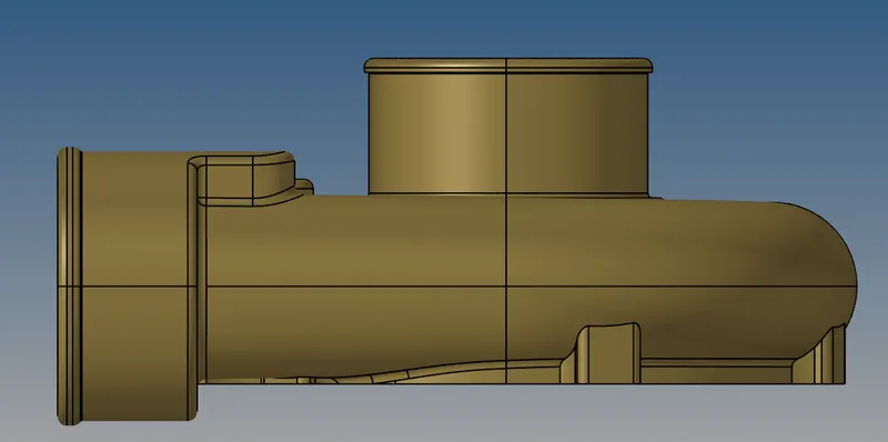
- The objective is to create tetra mesh using the 2D to 3D conversion method of the below geometry.
- The objective is to create tetra mesh using the 2D to 3D conversion method of the below geometry.
- Procedure:
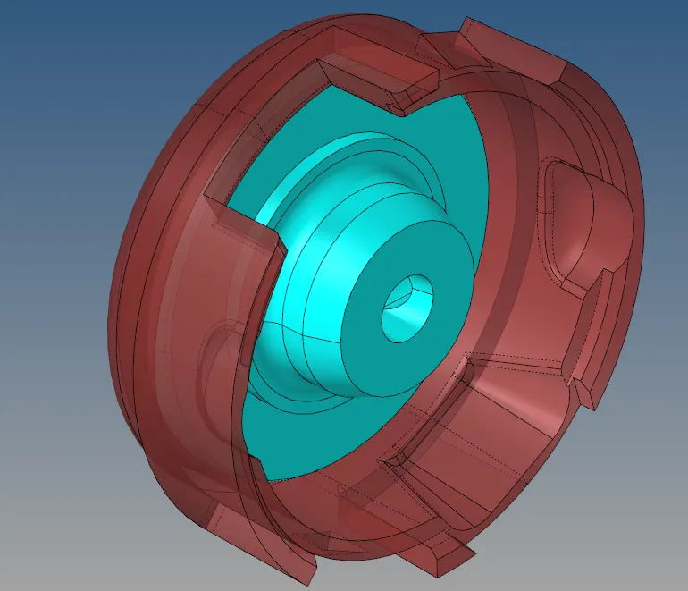
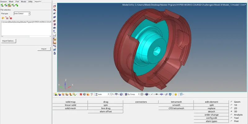
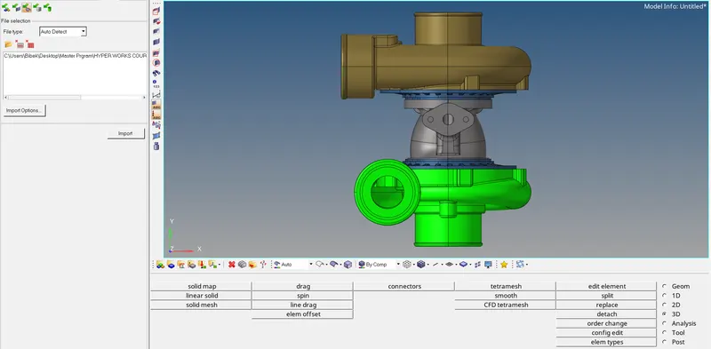
- The first is to import the first mode into the Hypermesh GUI.
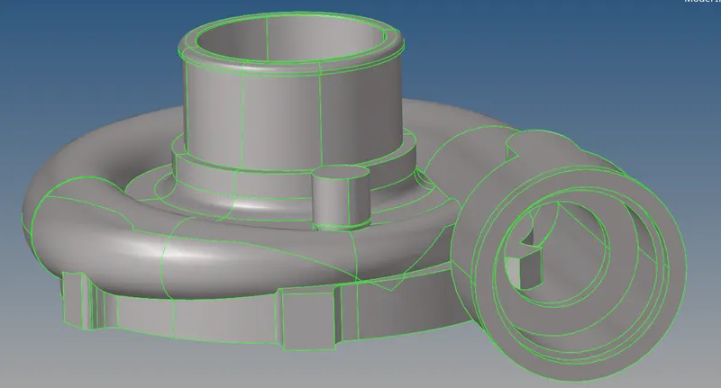
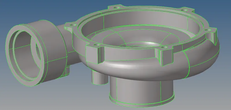
- As there are two different components in the geometry we have to mesh it differently. First bringing one component into the GUI.
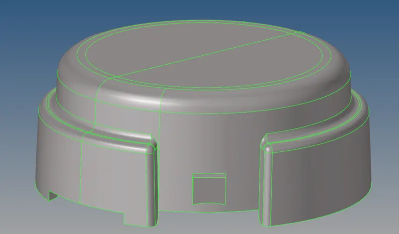
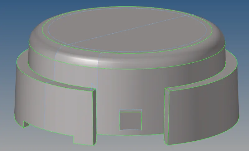
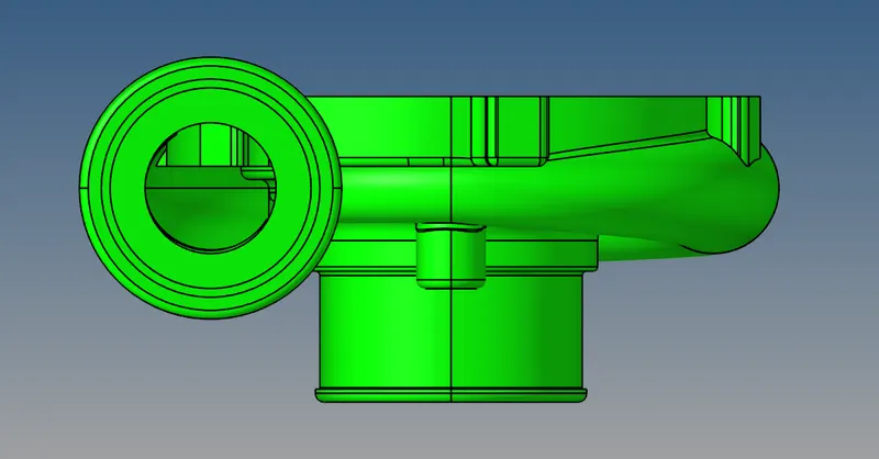
- Then delete the solids and keep only the surface to make surface meshing first. The geometry is given below
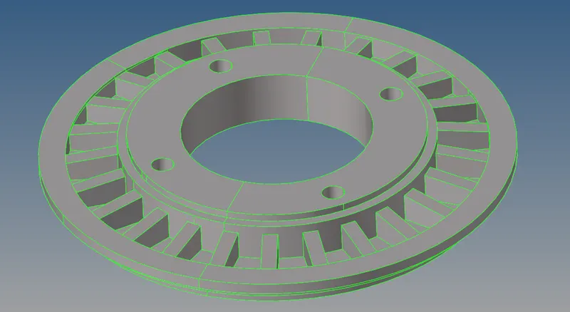
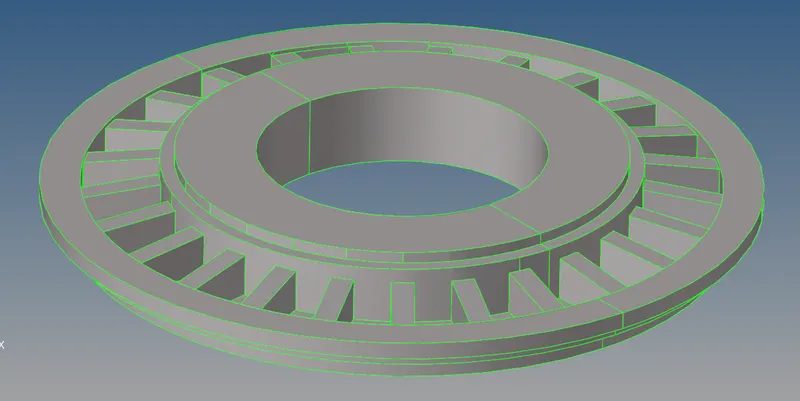
- Then bring the second component to the Hypermesh GUI
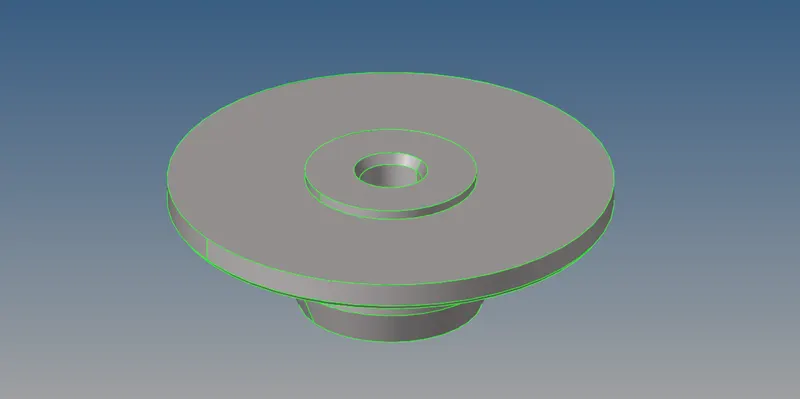
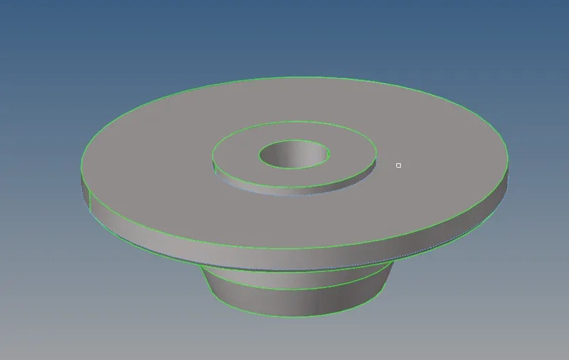
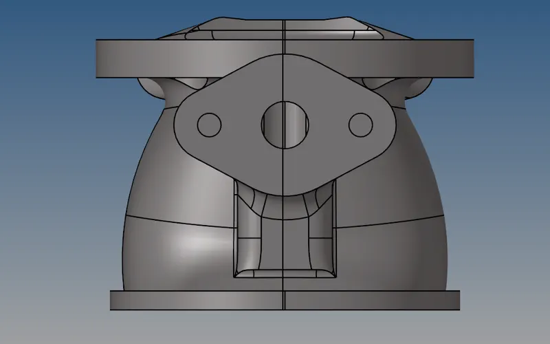
- Then delete the solids and keep only the surface to make surface meshing first. The geometry is given below
- The next step is to clean the geometry as there are much more complexities such as surface fillets, sharp edges, and small corners which can cause an element failure. So to avoid these failures we have to clean it before the meshing process.
- The cleaned geometry of the first component is given below
- The cleaned geometry of the second component is given below
- The cleaned geometry of the first component is given below
- Then attempted a mesh with triangular elements and the result is given below
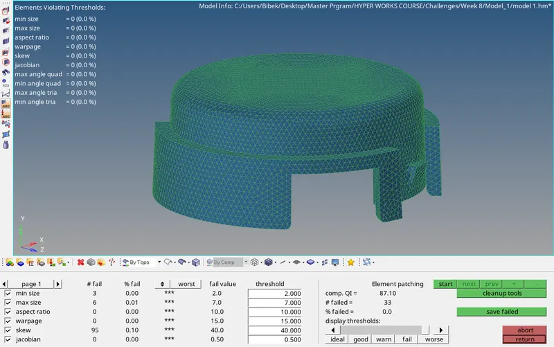
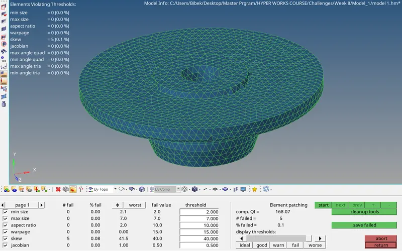
- As required quality criteria mentioned in the question statement, the quality has been checked and the results are given below
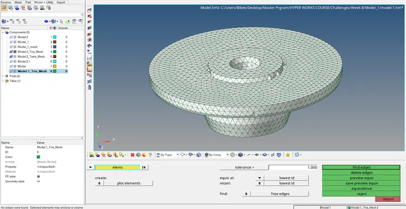
- Then check if any free edges are present in the meshed surfaces,
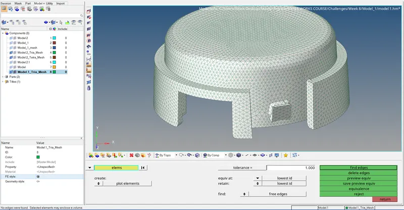
- Free edges for the second meshed component is checked below
- Free edges for the second meshed component is checked below
- Free edges for the second meshed component is checked below
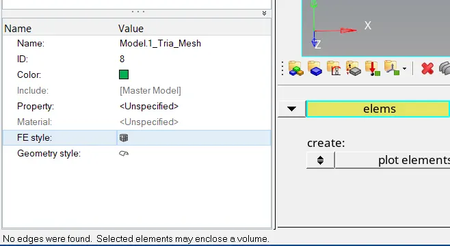
- As there are no free edges present in the 2D tria mesh, we can progress with the 3D tetra mesh. The tetra mesh can be done using the tetra mesh option present in the 3D panel.
- The tetra meshed body is given below
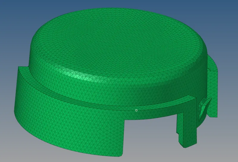
- 3D tetra mesh of the first component is shown below
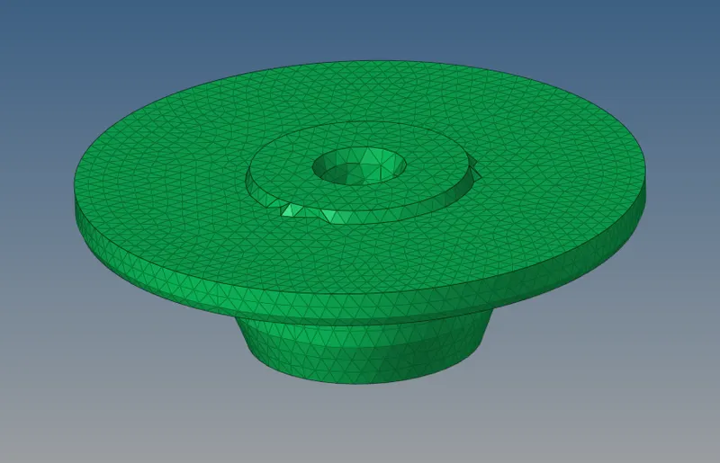
- 3D tetra mesh of the second component is shown below
- 3D tetra mesh of the first component is shown below
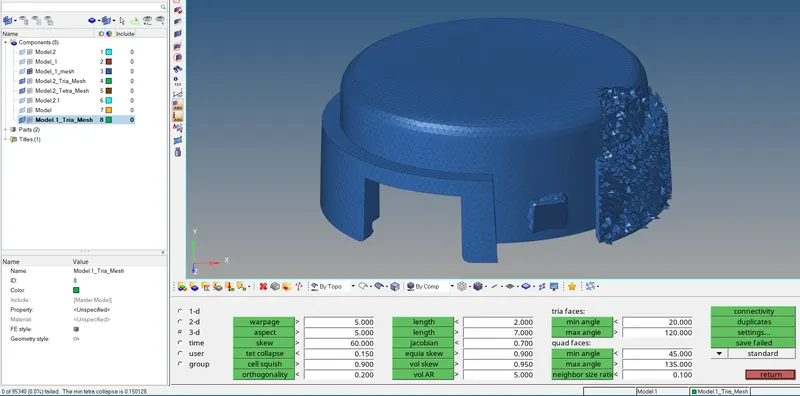
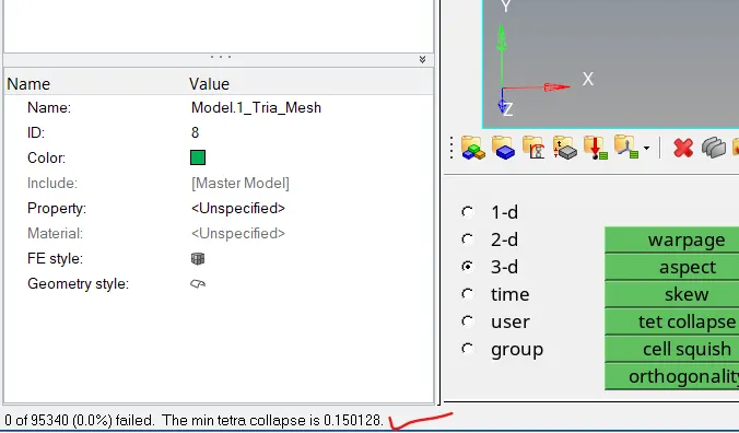
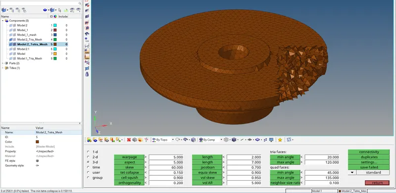
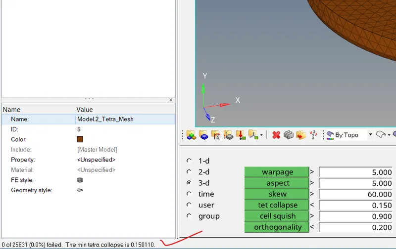
- The next step is to check whether the 3D tetra elements fit into the required quality criteria
- The results for the first model is given below
- The results for the second model is given below
- The results for the first model is given below
- The first is to import the first mode into the Hypermesh GUI.



Model-2
- Objective:
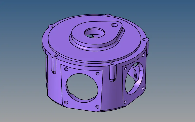
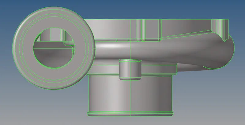
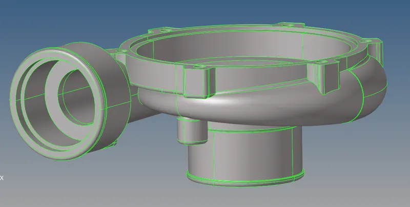
- The objective here is to create a 3D tetra mesh with a direct mesh generation method for the following geometry.
- The objective here is to create a 3D tetra mesh with a direct mesh generation method for the following geometry.
- Procedure:
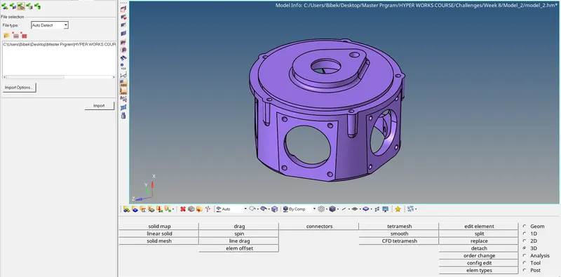
- The first step is to import the geometry into the Hypermesh GUI.
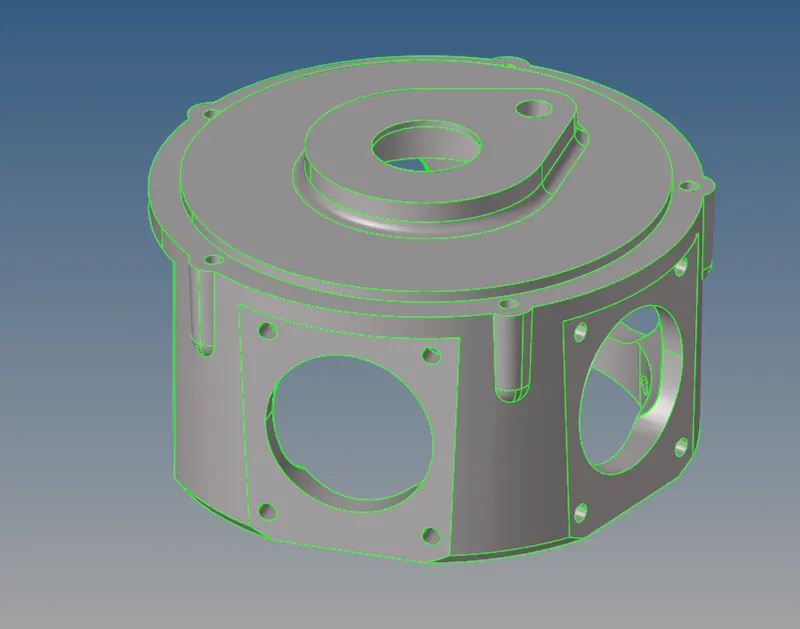
- As we can see in the above figure the geometry is solid so first, we have to delete the solid so that we can work with surfaces. The surfaces are given below
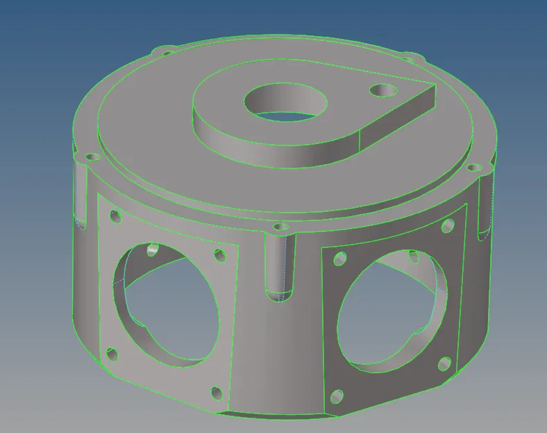
- As we can see the above surfaces has many surface fillets, sharp edges, and small trim bodies which can be a reason for the inappropriate geometry capture, to avoid those we have to clean the geometry before attempting 3D tetra mesh. The cleaned geometry is given below
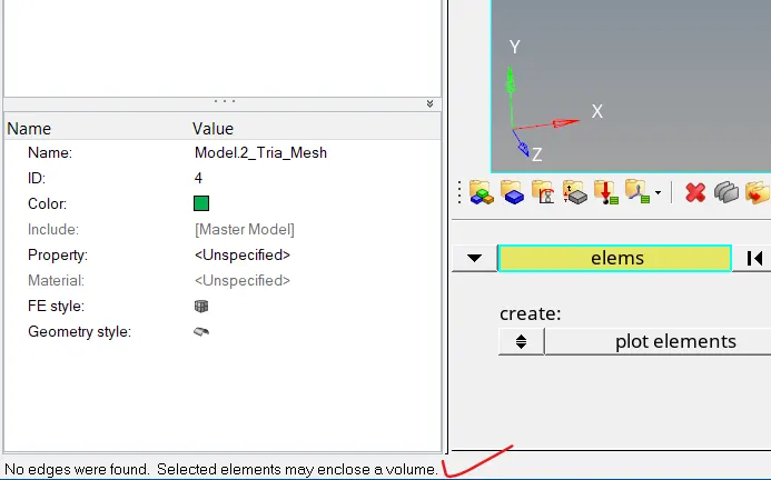
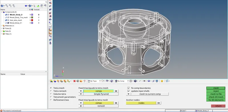
- After cleaning the geometry I tried meshing the body using the tetra mesh option present in the 3D section, but the error popped which shows the geometry is not closed but couldn't find any free edges.
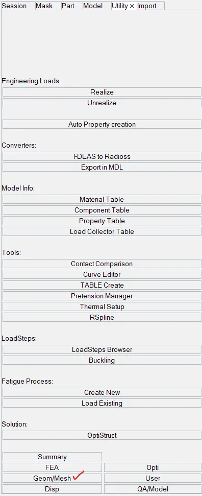
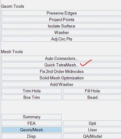
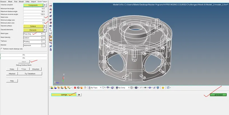
- To overcome this problem we have to use the utility option. Then we have to select the mesh option present in the utility and select the quick tetra option to make a tetra mesh of the given component.
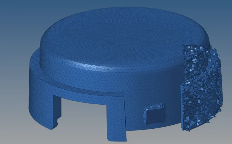
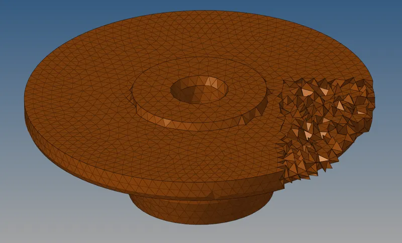
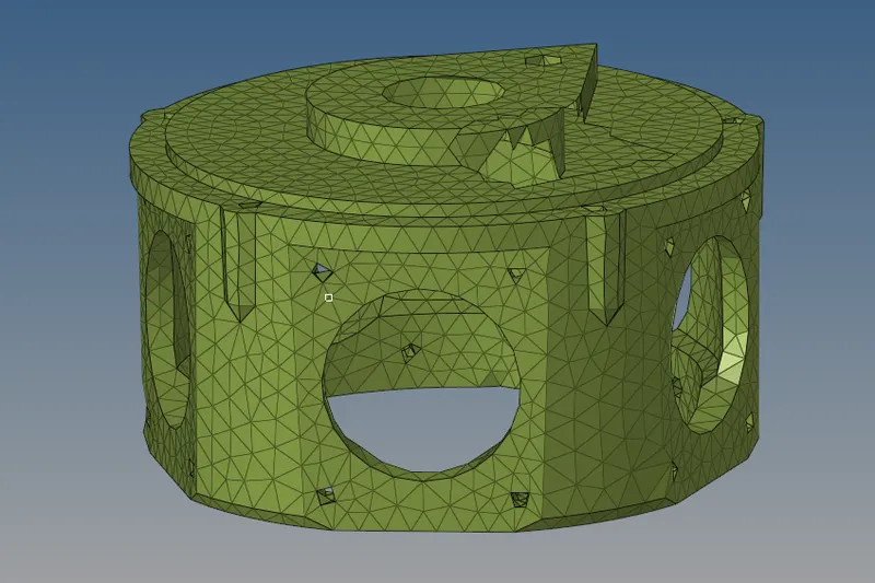
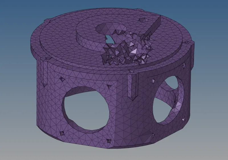
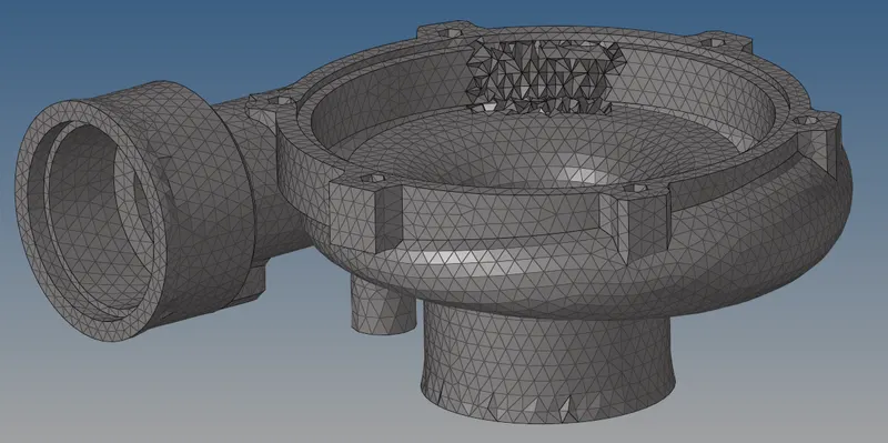
- The above procedure produces two mesh one is surface 2D tria mesh and another one is volume 3D tetra mesh. The mesh is given below
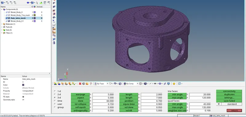
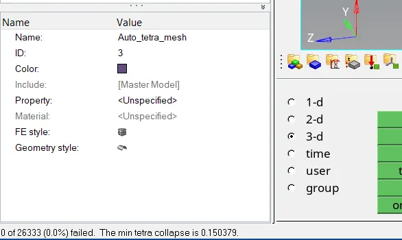
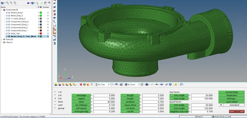
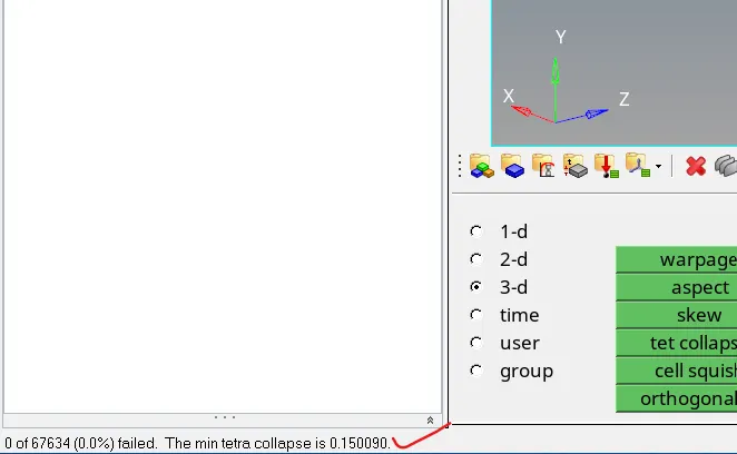
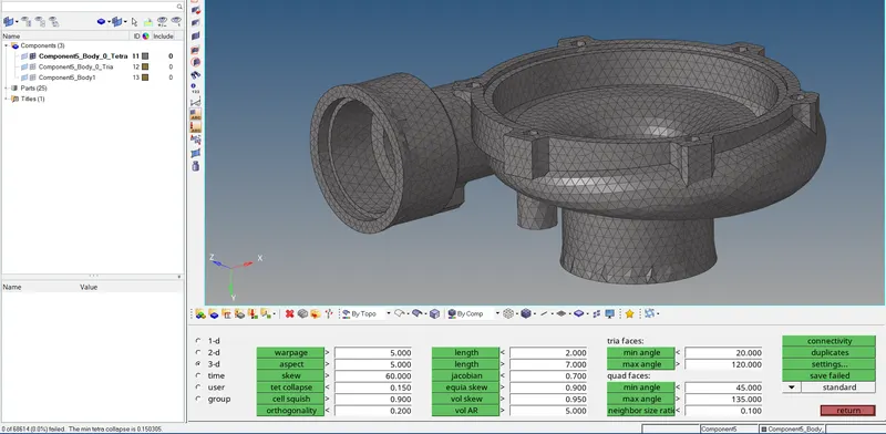
- Now checking the quality of the tetra mesh which is tet collapse =0.15
-
- The first step is to import the geometry into the Hypermesh GUI.
Model-3
- Objective:
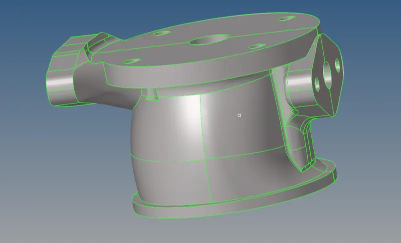
- The objective of this part is to generate a volume 3D mesh satisfying the given quality criteria mentioned in the question. The model is given below.
- The objective of this part is to generate a volume 3D mesh satisfying the given quality criteria mentioned in the question. The model is given below.
- Procedure:
- The first step is to import the geometry to the Hypermesh GUI
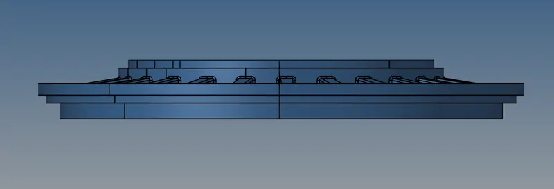
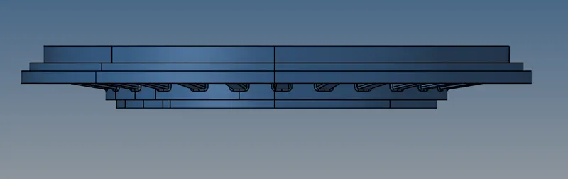
- As we can see from the above figure there are five components
- Model_Body_0, let's say it, 1st component.
-
- 1-1-solid1_Body_0, let's say it, 2nd component.
- Component13_Body_0, let's say it, 3rd component.
- Component13_Body_1, let's say it, 4th component.
- Component5_Body_0, let's say it, 5th model.
- Model_Body_0, let's say it, 1st component.
- Let's focus on each component serially, the first step is to bring the component into the hypermesh GUI and check whether it is a solid component or surface component.
- The 1st component surface is
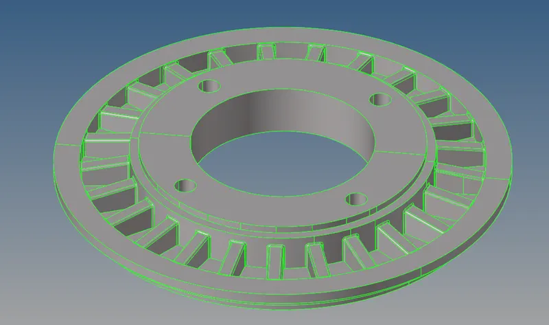
- The 2nd component surface is
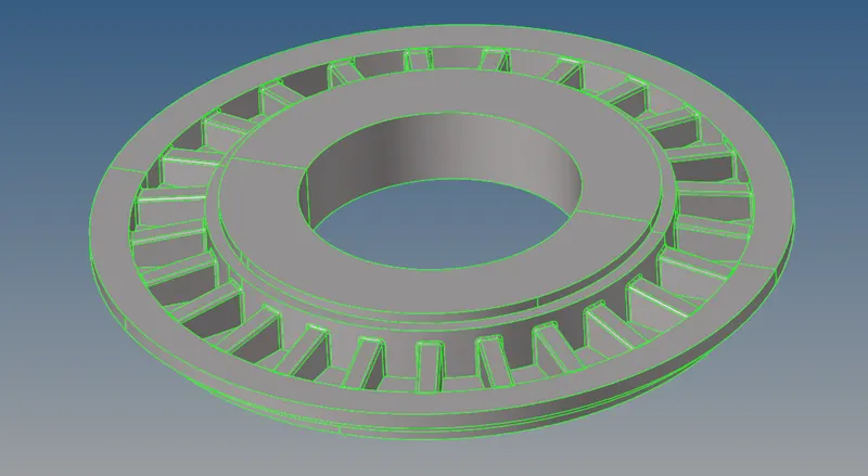
- The 3rd component surface is
- The 4th component surface is
- The 5th component surface is
- The 1st component surface is
- Topology cleanup
- As the 1st component has a lot of surface fillets, sharp edges and unwanted surface trims.
- The cleaned up 2nd component is given below
- The cleaned-up 3rd component is given below
- The cleaned-up 4th component is given below
- The cleaned-up 5th component is given below
- As the 1st component has a lot of surface fillets, sharp edges and unwanted surface trims.
- The next step is to check whether the component is able to generate3D mesh.
- In the 1st component, the component is unable to generate mesh, so we will take another path. To overcome this problem we have to use the utility option. Then we have to select the mesh option present in the utility and select the quick tetra option to make a tetra mesh of the given component.
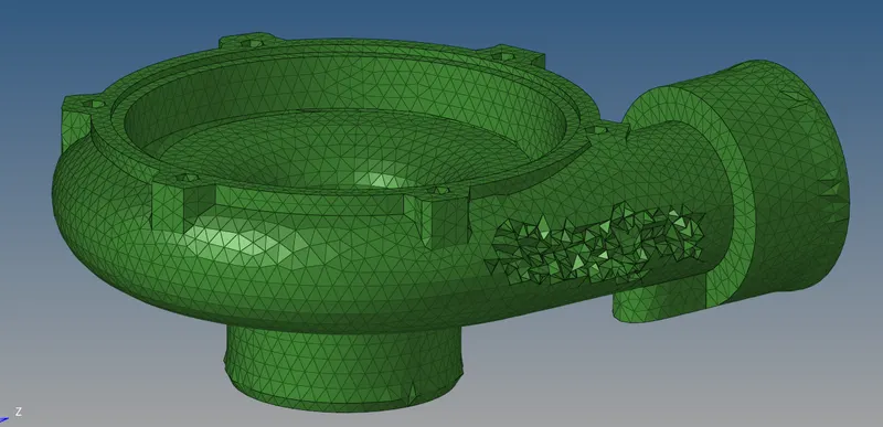
- The generated 3D tetra mesh for the 1st component is given below
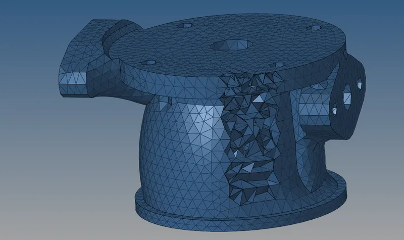
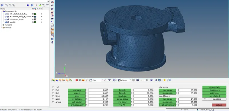
- The generated 3D tetra mesh for the 2st component is given below
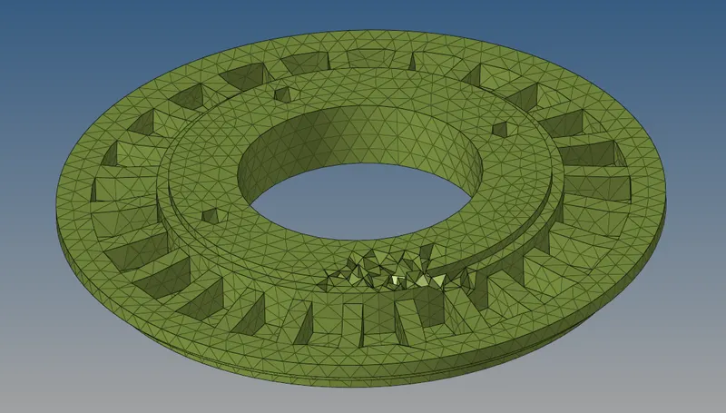
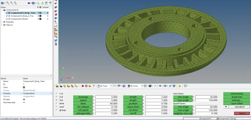
- The generated 3D tetra mesh for the 3rd component is given below
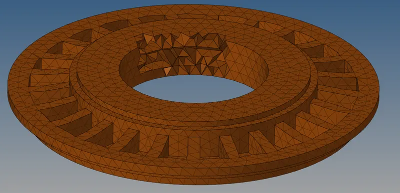
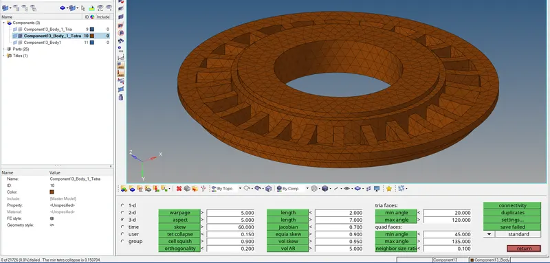
- The generated 3D tetra mesh for the 4th component is given below
- The generated 3D tetra mesh for the 5th component is given below
- In the 1st component, the component is unable to generate mesh, so we will take another path. To overcome this problem we have to use the utility option. Then we have to select the mesh option present in the utility and select the quick tetra option to make a tetra mesh of the given component.
- Now checking the quality of the tetra mesh which is tet collapse =0.15
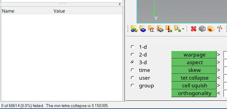
- Quality check of the 3D tetra mesh of the 1st component is given below
- Quality check of the 3D tetra mesh of the 2nd component is given below
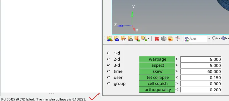
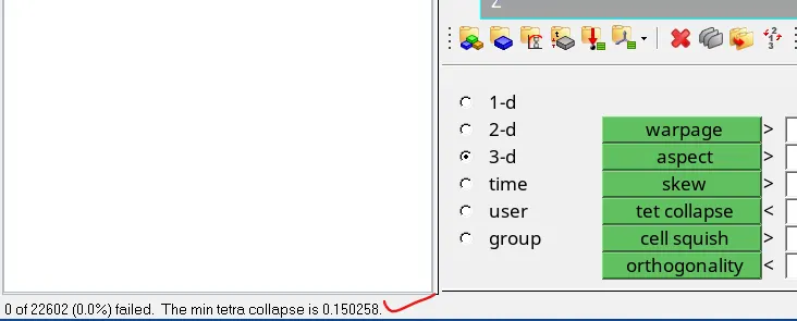
- Quality check of the 3D tetra mesh of the 3rd component is given below
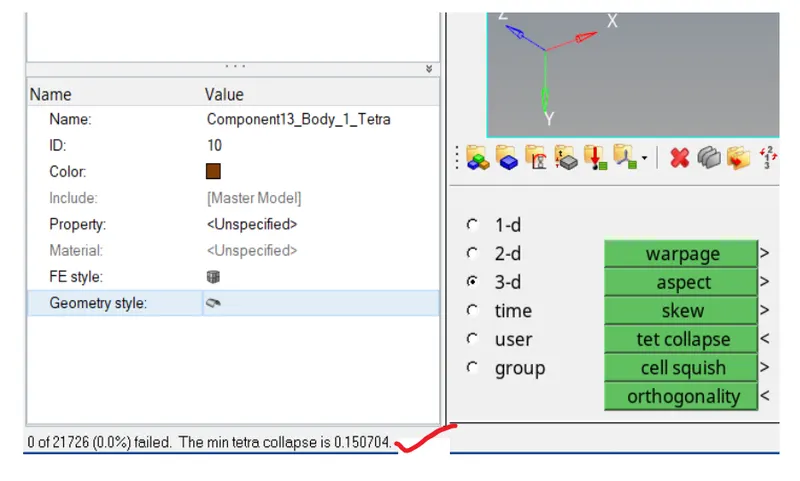
- Quality check of the 3D tetra mesh of the 4th component is given below
- Quality check of the 3D tetra mesh of the 4th component is given below
- Quality check of the 3D tetra mesh of the 1st component is given below
- The first step is to import the geometry to the Hypermesh GUI
Conclusion
- I've learned about some of the crude methods to generate tetra mesh from the volumetric components.