Week-7 Challenge: DC Motor Control
1. A. Explain a MATLAB demo model named ‘Speed control of a DC motor using BJT H-bridge’.
B. Comment on the armature current shoot-up from the scope results.
C. Refer to the help section of ‘The Four-Quadrant Chopper DC Drive (DC7) block’. Compare it with the H-bridge model.
BJT H-Bridge
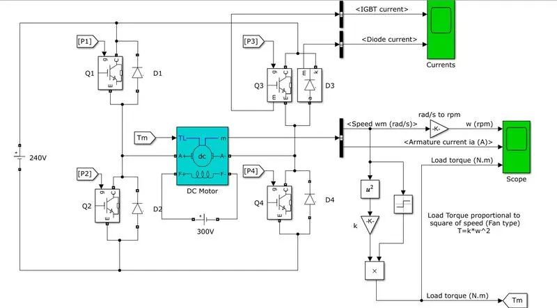
When the BJT is conducting that means it is operating in the saturated region, there will be a forward voltage developed between the collector and emitter. An IGBT is used to model the BJT because of this property. The switch is controlled by a SIMULINK signal. The DC motor used in this model is preset to with specifications: 5 HP, 24 V, 1750 rpm. It simulates a fan type lode where the load is proportional to the square of the speed. The mean armature voltage can be varied between 0 and 240 V when the duty cycle is changed anywhere from 0 to 100%. The duty cycle can be changed from the pulse generator block.
The BJT - H bridge consists of 4 BJT and Diode pairs. Two transistors ate switched on simultaneously: Q1 and Q4 or Q2 and Q3. When Q1 and Q4 are fired, a positive voltage is applied to the motor, and the diodes, D2 and D3 operate as free wheeling diodes when Q1 and Q4 are switched off. Similarly, when Q2 and Q3 are fired, a negative voltage is applied to the motor and the diodes Dq and D4 operate as free wheeling diodes when Q2 and Q3 are switched off.
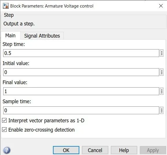
By default, the motor will start in the positive direction and has a preset duty cycle of 75% with a mean DC voltage of 180V. At t=0.5 seconds, the armature voltage will reverse and the motor will run in the negative direction.
SIMULINK model for the BJT-H Bridge used in the speed control of a DC motor.
The pulse generator with armature voltage is shown here
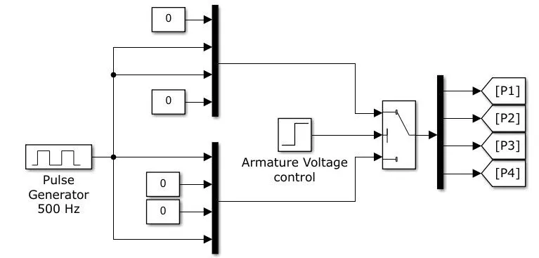
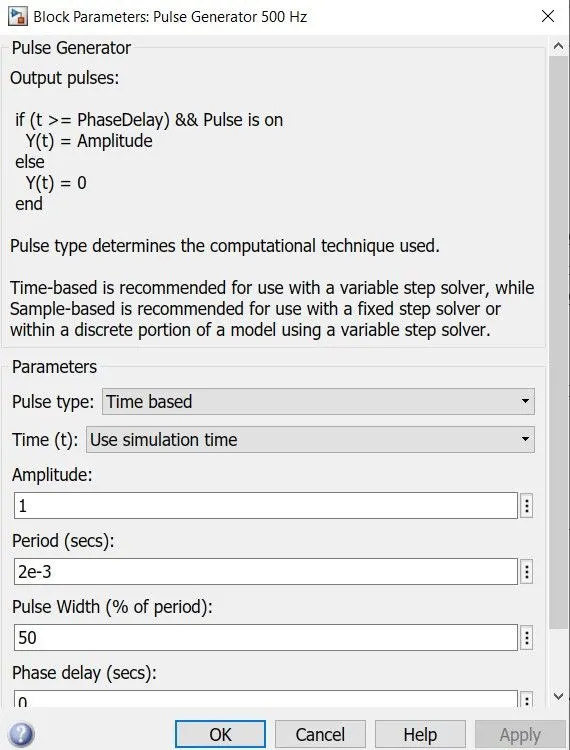
Here, we can see the 'Pulse Generator 500Hz' block. If we open it, we will get a dialog box with its settings which is shown below:
The pulse generator block set is shown below
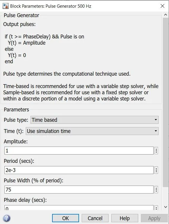
Here the pulse generator is already preset with some settings. The pulse width field allows us to modify the duty cycle of the motor and hence, we can prevent the motor current from shooting up when the motor changes its direction from forward to reverse. By default, the duty cycle is 75% meaning that the voltage is supplied to the motor for 75% of the time for one cycle. For the remaining 25%, the motor is off and receives no voltage from the source. It is this alternation between the ON and Off states, that allows us to vary the voltage that is supplied to the motor and thereby control the speed of an electric vehicle.
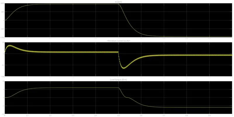
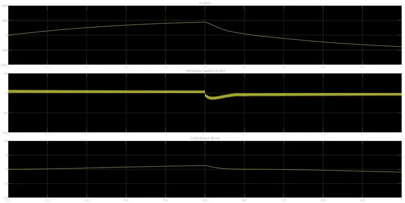
The scope below shows the plot of angular speed, armature current and the load torque all against a time axis.
B)
We are interested in modifying the simulation in order to prevent the initial shoot up of the armature current at the start of the cycle. This shoot up occurs whenever the armature voltage reverses direction which is every 0.5 seconds. In the second graph above we can see that at the start of the cycle, there is a sharp increase in the armature current that then decreases and comes to a more stable level where it remains until 0.5 seconds. When the next cycle begins, the exact same effect occurs but in the negative axis because in this cycle, the armature voltage is reversed.
The frequency of reversing the voltage direction has been preset in the armature voltage control block. Opening it will give you a frequency at which the voltage is reversed.
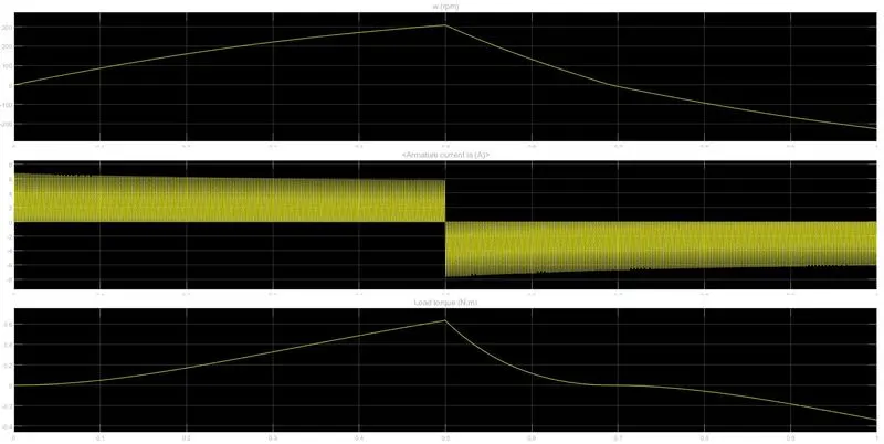
If we change the duty cycle that is the pulse width, we can control this initial shoot up of the current that occurs every time the armature voltage direction is reversed. When the duty cycle is decreased to 50% the output graph that is obtained is shown below:
For the 50% duty cycle, we can see that armature current does not shoot up initially for the positive direction of the armature voltage. However, after the 0.5-second mark when the armature voltage is reversed, the armature current shoots up in the negative direction. So, we need to decrease the duty cycle further to prevent this. This time we have to reduce the duty cycle to 40%. The output will be
Here, we can see that at the start of the cycle in the positive armature voltage direction, the armature current does not shoot up as it did before. The armature current increases immediately to approximately 7A and it maintains that level until the next cycle where the armature voltage is reversed to -7A.
2. Develop a 2-quadrant chopper using Simulink & explain the working of the same with the relevant results. (Refer to article - Multiquadrant operation of motor )
Ans-
Two Quadrant Chopper
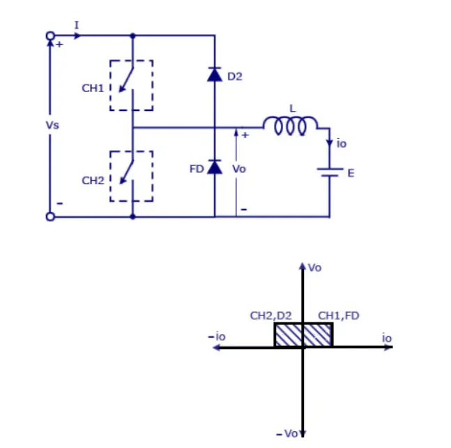
The average voltage will be always positive but the average load current might be positive or negative. The two switches CH 1 and CH 2 should not be turned on simultaneously as the combined action may cause a short circuit in supply lines. For regenerative braking and motoring, this type of chopper configuration is used.
We will always get a positive output voltage Vo as the freewheeling diode FD is present across the load. The inductor stores energy, when CH1 turns off the freewheeling diode starts conducting and the output voltage Vo will be reversed. The current i0 will be flowing toward the source. The load current will be negative when the CH 2 is on. The current completes its path through diode D2.
Chopper
A dc-dc converter, is also known as a chopper, is a static device which is used to obtain a variable dc voltage from a constant dc voltage source. Choppers are widely used in trolley cars, battery operated vehicles, traction motor control, control of large numbers of dc motors, etc. They are also used as dc voltage regulators. Choppers are of two types:
- Step down choppers- The output voltage will be less than the input voltage
- Step up choppers - the output voltage will be more than the input voltage
The SIMULINK model for 2 quadrant chopper
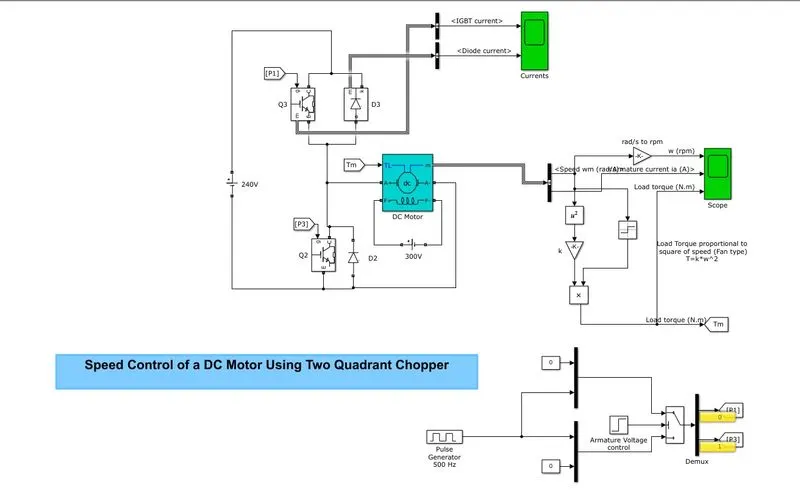
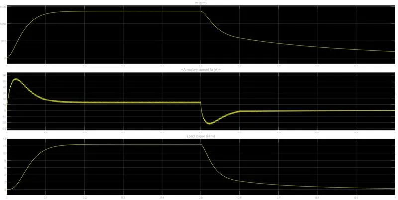
Here IGBT's are used as the switch for the operation of the controller. The two-quadrant control can be used for forward motoring and reverse braking. Here the load torque is taken as fan load type. The plots are given below
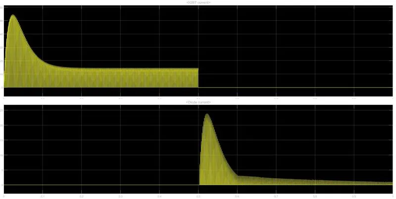
The plot for the current in diode and IGBT is given as
Conclusion
- The 2 quadrant chopper is not complete and can not achieve all requirements for an EV.
- It is restricted to very low usefulness and has a very specific usage.
- There has to be active cooling for the power converter in order to run efficiently.
- The diodes provided in order to reduce the chances of damage to the IGBT.
3. Explain in a brief about the operation of the BLDC motor.
Usually, the brushes change the polarity of the ole to keep the rotation on of the armature. The basic working principle for the brushed DC motor and for brushless DC motor are dame that is internal shaft position feedback.
A Brushless DC motor has only two basic parts: the rotor and the stator. The rotor is the rotating part and has rotor magnets whereas the stator is the stationary part and contains stator windings. In BLDC permanent magnets are attached to the rotor and move the electromagnets for the shaft turns. The controller performs power distribution by using a solid-state circuit.
Basically, BLDC are of two types,
- Puter rotor motor
- Inner rotor motor
Inner rotor design
In an inner rotor design, the rotor is located in the center of the motor and the stator winding surrounds the rotor. As the rotor is located in the core, rotor magnets do not insulate heat inside and heat gets dissipated easily. Due to this reason, the inner rotor-designed motor produces a large amount of torque and validly used.
Outer rotor design
In outer rotor design, the rotor surrounds the winding which is located in the core of the motor. The magnets in the rotor trap the heat of the motor inside and do not allow it to dissipate from the motor. Such type of designed motor operates at a lower-rated current and has low cogging torque.
Disadvantages of a BLDC motor are:
- BLDC motor cost more than a brushed DC motor.
- The limited high power could be supplied to the BLDC motor, otherwise, too much heat weakens the magnets and the insulation of winding may get damaged.