Week-6 Challenge: EV Drivetrain
1. Which types of power converter circuits are employed in an electric and hybrid electric vehicles?
Introduction to the Power converter
- Power electronics technology deals with processing and controlling the flow of electrical energy in order to supply voltages and currents in a form that optimally suited for the end user's requirements.
- A power electronic converter uses power electronic components such as SCRs, TRIACs, IGBTs, etc to control and convert the electric power. The main aim of the converter is to produce conditioning power with respect to a certain application.
- The power electronic consists of both power parts and control parts.
- The power part transfers the energy from source to load and it consists of power electronic switches, transformers, electric choke, capacitors, fuses, and resistors.
- The control part regulates the elements in the power part of the converter. This is built with a complex low power electronic circuit that consists of either analog or digital circuit assembly.
Different types of power electronic converter
- AC to DC = Rectifier: It converts AC to unipolar (DC) current
- DC to AC = Inverter: It converts DC to AC of desired frequency and voltage
- DC to DC = Chopper: It converts constant to variable DC or variable DC to constant DC
- AC to AC = Cycloconverter, Matrix converter: It converts AC of the desired frequency and/or desired voltage magnitude from a line AC supply.
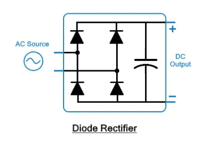
- Diode Rectifier(AC to DC)
The Diode Rectifier converts AC power to fixed DC power. The applied input voltage can be single phase or three phase. The input alternating voltage is converted into a steady and smoother DC output.
- Inverter (DC-AC)
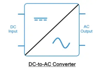
DC-AC converters convert the input DC power into AC power. These converters are also known as inverters. There are a lot of different types of inverters; however, a typical inveter uses four switches or thyristors. The four switches make 2 pairs, individually controlled by a switching circuit where each pair is switched on at one interval of time. This alternating switching of the thyristors provides an alternating current through the load. This rhythm of turning the switches changes the DC voltage into AC across the load. The output voltage of the circuit can be directly controlled by changing the conduction time of the switch using the switching circuit.
- Chopper (DC-DC)
DC-DC converters convert or change the voltage level of applied DC input into a different DC output. These converters are also known as choppers, or a transistor chopper, or switching regulator. The average output voltage of the converter circuit can be directly controlled by changing the conduction time of the controlled switch. The conduction time t of the switch is the product of the duty cycle and chopping period
`t=D*T`
where,
D = duty cycle of the chopper
T = chopping period
- Cycloconverter(AC to AC)
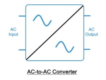
These converters convert the fixed AC source into variable AC output voltage. A single phase AC-AC converter has a TRIAC. By varying the conduction time of TRIAC, the output voltage of converter can be controlled directly. AC-AC converters are also known as AC voltage controllers.
2. An Electric Vehicle's powertrain with 72V battery pack in shown in the diagram below. The duty ratio for acceleration operation is 'd1' and for the braking operation the duty ratio is 'd2'.
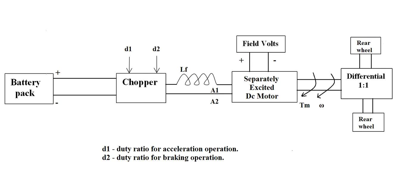
The other parameters of the electric vehicle is given below,
Motor and Controller Parameters:
Rated Armature voltage= 72 V
Rated armature current= 400 A
Ra= 0.5Ω, KΦ= 0.7 Volt second
Chopper Switching frequency= 400 Hz
The vehicle speed-torque characteristics are given by the below equation

What is EV steady state speed if duty cycle is 70%?
Given,
Rated motor voltage (`Vunderset(batery)`) = 72 V
Duty cycle = 70%
Supplied voltage = `70*0.7`= 50.4 V
Internal resistance of motor (`Runderseta`) = 0.5 `Omega`
Motor constant (`Kundersetphi`) = 0.7 V.sec
Chopper switching frequency (f) = 400 Hz
Let, speed of vehicle and motor be = `omega`
The vehicle speed-torque characteristics are given by the below equation is
`rArr`--------------------> Eq 1
Now, motor torque characteristics
`rArr``Tunderset(m)() =( V*Kunderset(phi)())/(Runderset(a)())-(Kunderset(phi)())^2/(Runderset(a)())*omega`
which equals to
`rArr` `Tunderset(m)()=(50.4*0.7)/(0.5)-(0.7)^2/0.5*omega` ----------------> Eq 2
`rArr` `Tunderset(m)()=70.56-0.98*omega`
equation Eq 1 and Eq 2
`rArr``70.56-0.98*omega=24.7+0.0051omega^2`
`rArr``0.0051omega^2+0.98*omega-45.86=0`
After solving we get two solutions = 38.91 and -231.01
since the speed can never be negative so the steady state speed value is = 38.91 rad/s
3. Develop a mathematical model of a DC Motor for the below equation using Simulink.
ω">ωω= V/Kϕ">ϕϕ -Ra/Kϕ">ϕϕ^2 .T
The mathemetical model which I built was
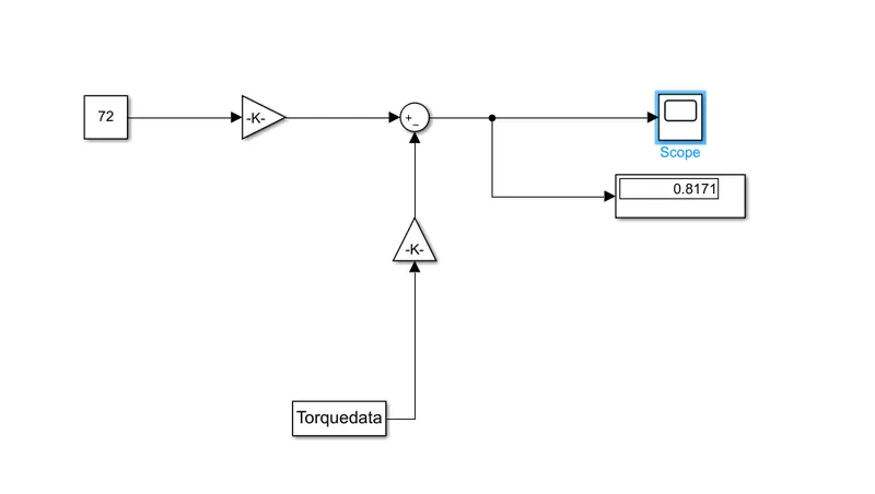
I took a matrix data of torque and gave input in simulink and found out the speed and plotted in the scope and it came out as a straight line,
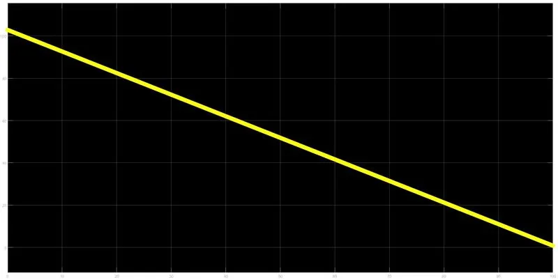
The rest of my files I've attached.
4. Refer to the blog on below topic:
Induction Versus DC brushless motors by Wally Rippel, Tesla
Explain in brief about author’s perspective.
The blog emphasizes the type of motors and how design decisions are made regarding the usage of the vehicle. Also explaining the nuances the author here gave the Pro's and Cons of the
- AC Induction motor
- DC Brushless motor
Here he made a clear distinction about the differences similarities of the two motors and found that
- Similarities
- The stators for the 3-phase induction motor and the DC brushless motor are virtually identical.
- Both motors require an inverter in order to work under DC voltage. Where induction motor requires DC-AC inverter, DC brushless requires variable DC-DC converters. without these converter the DC brushless motors are useless.
- Differences
- The main differences are rotors.
- DC motor can run with unit power factor but the AC induction motor drive runs about 0.85 power factor.
- The peak point energy efficiency for a DC brushless drive will typically be a few percentages higher than that for an AC induction motor.
- The main losses in DC brushless motor is regarding the Eddy and Hysteresis losses due to magnetic field strength but we can't change the field strength in DC brushless drive because it has a permanent magnet type rotor. Here Induction motor has a strong point as it doesn't have any magnets.
Conclusion
The key takeaway is that ONE SIZE DOESN'T FIT ALL. This means there isn't one universal solution to a vast variety of problems. So a designer must keep the requirements in mind and design the drive as the necessity demands.