Week 8-3D Tetra Meshing Challenge
Objective:
To create 3D tetra mesh in the given components using different methods as mentioned and checking for tet collapse.
Procedure:
- The component has to be imported into the hypermesh.
MODEL 1
- The first model has two components and one is solid. Since we are supposed to create 2D elements first we only need the surface and not the solid. So we can delete the solid. The F2 key is pressed and the solid to be deleted is selected.
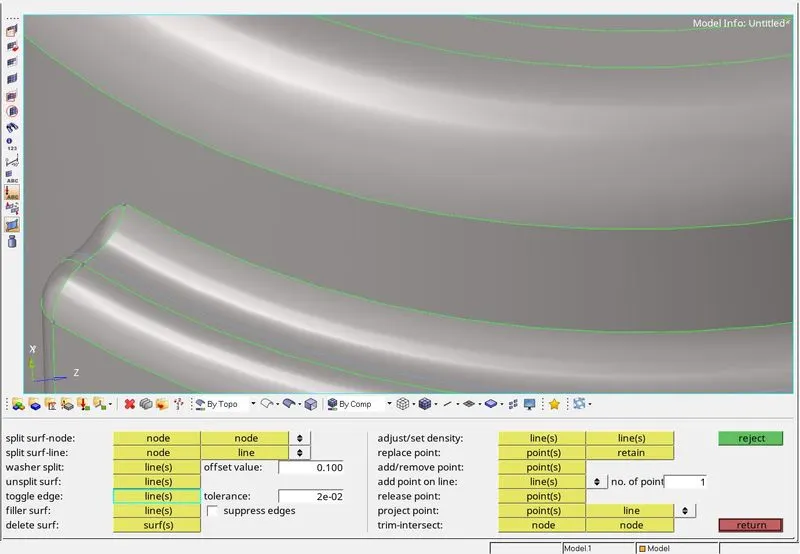
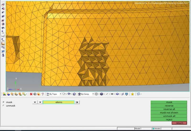
- Now geometry cleanup has to be done on the components before meshing. Surfaces that are smaller than the minimum element length are toggled in one edge as shown in the image below.
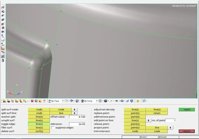
- Similarly, surfaces that have sharp corners will fail so the surface is cut using the surface split using node and line and the unwanted edges are toggled using the toggle option in the quickedit tab (F11 key). An example is shown below.
- After all such edges are cleaned up meshing is done. The mesh type trias is selected because we want to create 3D tetra mesh. The element size is given as 5 units. The F12 key is used to access the 2D mesh panel.
- The mesh is done in batches so that correcting the elements failing the maximum and minimum length criteria is easier to rectify.
- Free edges are checked after the elements are created.
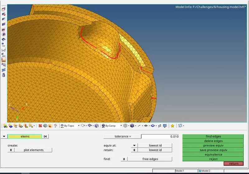
- The free edges are rectified using the equivalence option and the replace node option (F3 Key).
- The quality of the elements is checked using the qualityindex and the elements failing for the maximum and minimum length are corrected using the cleanup tools and the distance option in the geometry tab.
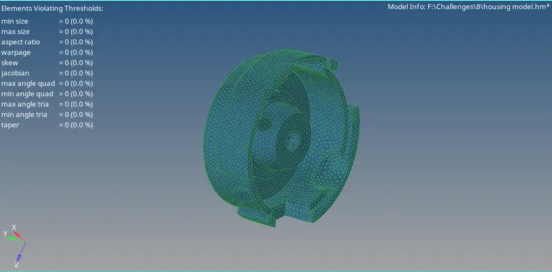
- Now the 3d elements are created using the tetramesh option under the 3D tab. The tetra mesh option is used and the elements are selected.
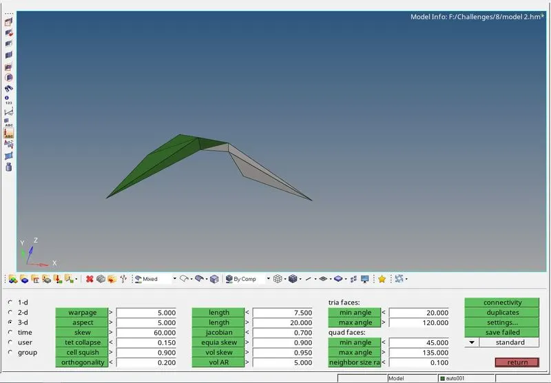
- After the 3D elements are created, they are checked for tet collapse using the check elems from the tools tab or by pressing the F10 key. In the 3D tab, the tet collapse value is given as 0.15. The number of elements failing for tet collapse is shown.
- These can be rectified by using the terta remesh option. Before remeshing, in the tetramesh parameters the tet collapse value is given as 0.15 and the max tetra size is checked and the value is given as 7 which is the default and the fill voids, fix midnodes, and smoothing are checked.

- Now the tetra remesh option is used and the elements to be remeshed are selected.
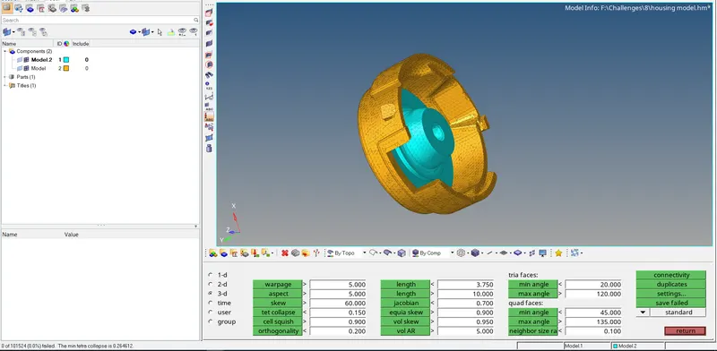
- As shown in the above image, no elements fail for tet collapse.
MODEL 2
- In this, the 3D tetra mesh is to be created using the volume tetra method. Since the mesh is created using the volume tetra method no surface cleanup is done on the geometry.
- One way to remove tet collapse elements is by using the distance option and manually changing the distance between the nodes but this is tedious.
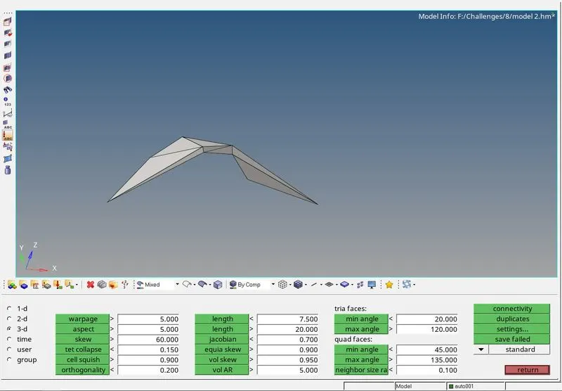
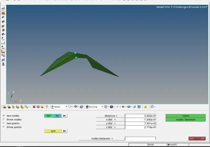
- Before meshing in the tetramesh parameters option the tet collapse value is given as 0.15 and the max tetra size is checked and the value is given as 7 which is default and the fill voids, fix midnodes, and smoothing are checked.
- In the volume tetramesh the use curvature and use, proximity options are checked to reduce the number of tet collapse elements. The element size is given as 3 units.
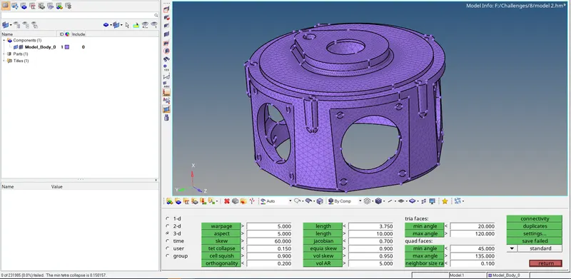
- The elements are checked for tet collapse using the Check elems option.
MODEL 3
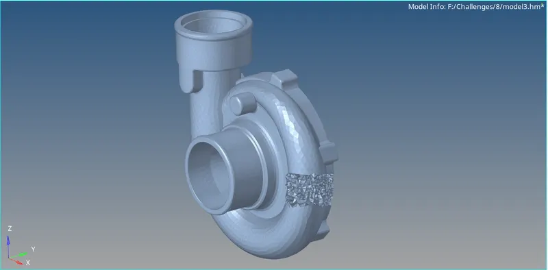
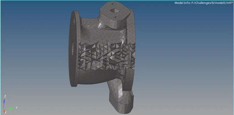
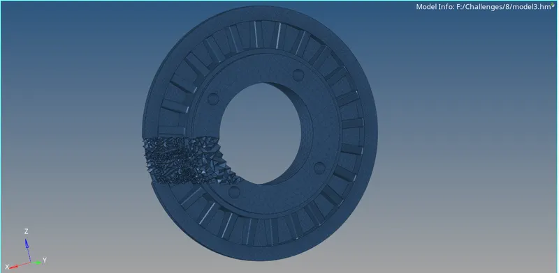
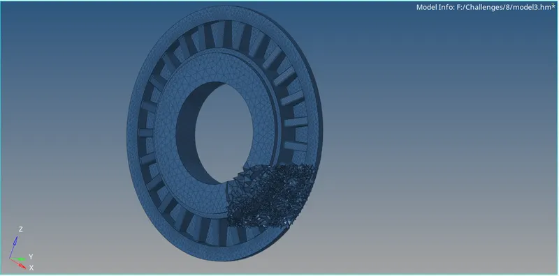
- In the 3rd model, there are a total of 5 components. Each of these components has to be meshed using the volume tetra method. Similar to how model 2 was meshed, in the tetramesh parameters the tet collapse value is given as 0.15 and the max tetra size is checked and the value is given as 7 which is the default and the fill voids, fix midnodes, and smoothing are checked. In the volume tetramesh the use curvature and use, proximity options are checked to reduce the number of tet collapse elements. The element size is given as 4 units in the volume tetramesh.
- Because there are 5 components to avoid the segmentation error one of the components has meshed in a separate file.
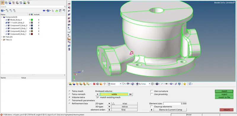
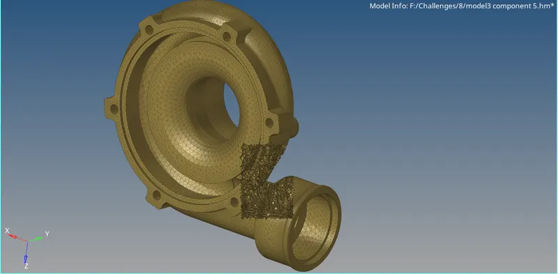
- In one component there is an intersection and because of this, the mesh is not created (shown in the image below). To create the mesh we toggle the edge.
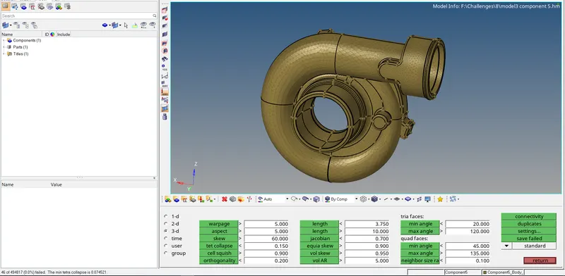
- After the elements are created the elements that fail for tet collapse using the check elems option.
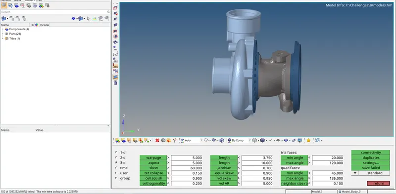
Final model images:
MODEL 1
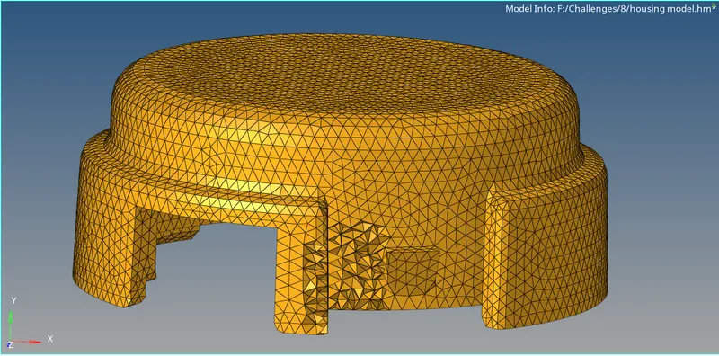
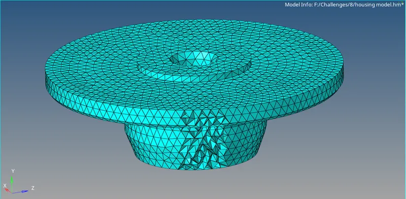
MODEL 2
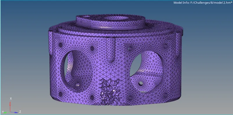
MODEL 3:
Results:
The 3D tetra mesh is created for all the 3 models and the tet collapse is 0% for all the components.