Week 12:Project 2-Meshing of Rear Wheel Holder challenge
Objective:
To extract the midsurface of the given component and mesh the surface satisfying the given quality criteria.
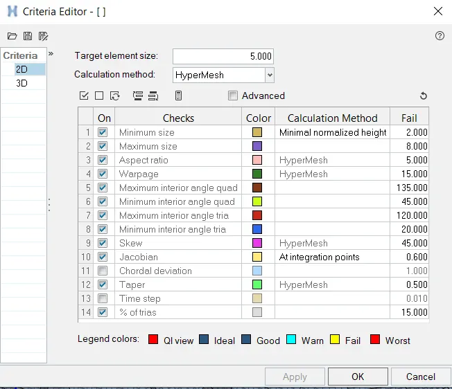
Quality Criteria:
Target Element Length = 5 Units
| S.N | Quality Criteria | Value |
| 1 | Aspect Ratio | 5 |
| 2 | Skewness | 45 |
| 3 | Warping | 15 |
| 4 | Taper | 0.5 |
| 5 | Min. Length | 2 Units |
| 6 | Max. Length | 8 Units |
| 7 | Min angle Quad | 45 |
| 8 | Max angle Quad | 135 |
| 9 | Min angle Tria | 20 |
| 10 | Max angle Tria | 120 |
| 10 | Tria % | 10 |
Procedure:
GEOMETRY CLEANUP & MIDSURFACE EXTRACTION
- The component is imported to Hypermesh using the Import Geometry option.
- After importing the part we delete the solids if any.
- Any free edges present are rectified using the toggle edge and the surface options.
- To check whether the auto midsurface option can be used, the thickness of the part is checked.
- To measure the thickness, points are added using the add/remove points option in the quick edit panel (F11 key).
- The added points are then projected onto the opposite planes using the project option (SHIFT+F7).
- Then the distance between the points is measured using the distance option (two points) (F4 key).
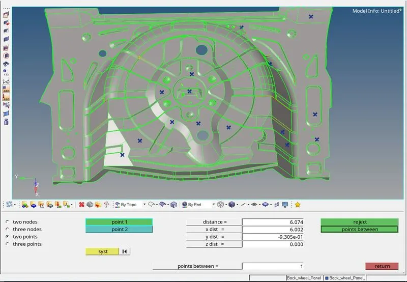
- The measured thickness was a uniform 0.75 units, therefore auto midsurface can be used.
- Before extracting the midsurface in the extraction options of the midsurface panel, the offset+planes+sweeps option is chosen. Then in the auto extraction option, the surfaces are chosen and the midsurface is extracted.
- Once the midsurface is generated all the surface imperfections like free edges, overlapping surfaces are rectified.
- To remove the free edges the toggle edges are used. If there are feature holes in the midsurface the washer split is added to get a proper mesh flow and to avoid trias attached to the free edges.

- If there is a missing surface, the Ruled or the spline/filler option (shown in the images below respectively) in the surface panel is used to create a new surface.


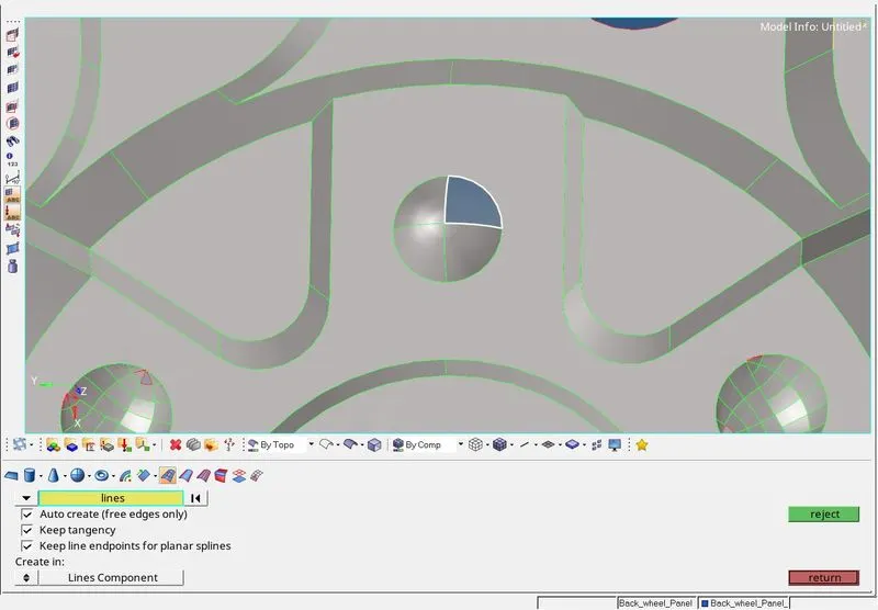
- Features that are too small to capture without causing the elements to fail are removed using the toggle option or the replace points option.
- The small circular surface that can't be captured is deleted and the filler surf option is used to create the surface.
- The toggle option is used to remove unnecessary cuts in the surface.
MESHING
- The automesh (F12 key) option is used to mesh the component. The surface is divided into small manageable regions so that we can have better control over the mesh flow.
- The given quality criteria are entered into the criteria file settings and the element color mode is set to By Element Quality.
- To remove the tria elements the mesh can be remeshed, the cleanup tools in the qualityindex can also be used.
- The drag tria elements option is used to remove tria elements, shown in the image below.

- The translate option is used to remove the warpage failure of elements.

- The distance option (F4 key) is used to eliminate the maximum and minimum length failure in elements.

- The Edges tool (SHIFT+F3) is used to find free edges in the elements.
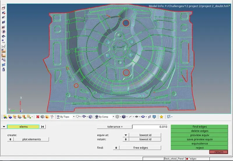
- These free edges can be rectified using the equivalence option and the nodes of the free edges within the given tolerance range will be joined.
- Using the equivalence option does not attach all the nodes some nodes have to be manually attached using the replace node option (F3 key).

ASSIGNING THICKNESS
- Thickness is assigned to the elements through a property. The card image is selected as P1_SHELL and the thickness value is entered in the thickness field.
- This property is then assigned to the component.
FINAL IMAGES
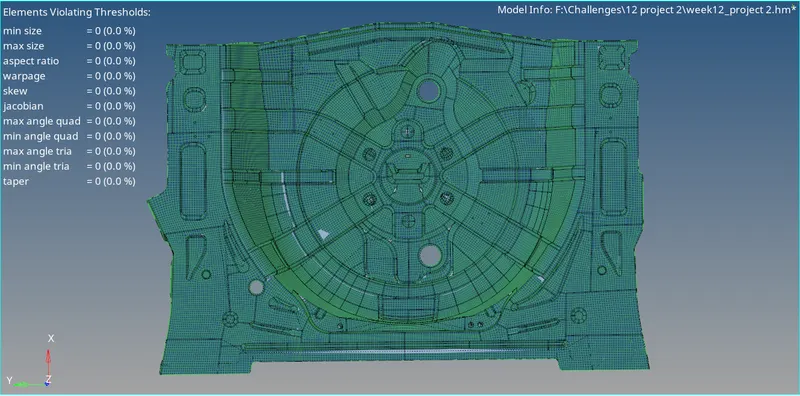
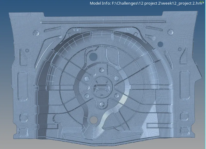
RESULT:
Midsurface was extracted for the given component and it was meshed with the elements satisfying the given quality criteria and thickness was assigned to the elements,