Week 4-1D Element Creation Challenge
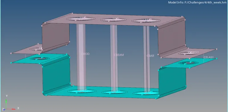
Objective: To mesh the given component with elements size of 5 units and create the mentioned 1-D components at the specified positions on the model.
Procedure: The model is first imported into Hypermesh.
- The first step is to create mid surfaces for the model.
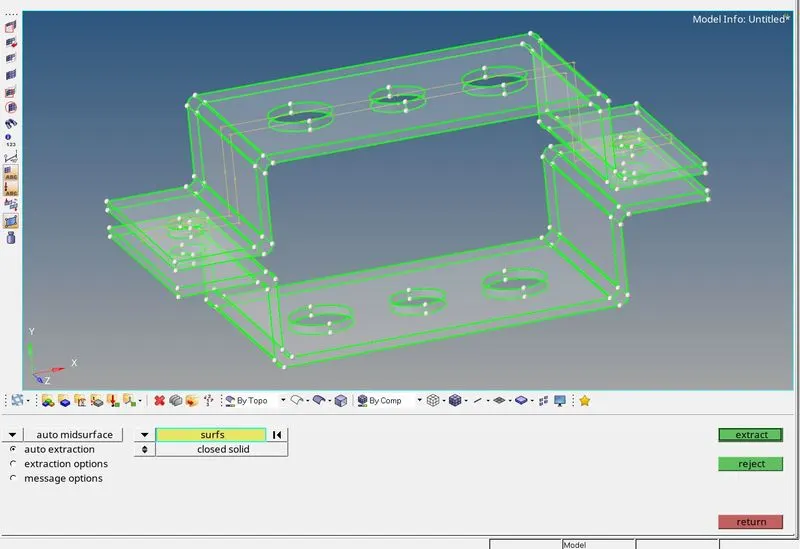
- The solids for which mid surfaces are needed are selected so that the mid surfaces will be created. In the extraction options, offset+planes are selected so that the created surfaces are individual surfaces and not a single surface.

- After the mid surfaces are created the solids are deleted and the component's surfaces are hidden.
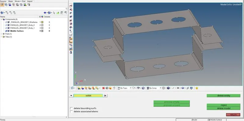
- The mid surfaces created are stored as a single component, so to make them into separate components, a component named 'Bottom' is created and the existing 'Middle Surface' is renamed to 'Top'.
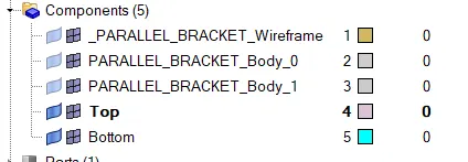
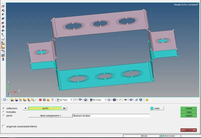
- To move one of the surfaces from the component 'Top' the Organise tool is used. Here, the surfaces to be moved should be selected and in the 'dest component' the component to which the surface is to be moved should be specified.
- To specify that the mesh elements should be of shell elements a property is created and associated with the 'Top' and 'Bottom' components.
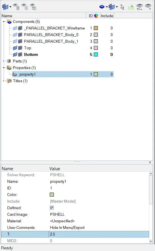
- In the above image, the thickness is specified as 2.5 mm and PSHELL is chosen.
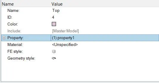
- The property created is associated with 'Top' in the image and the same is done with the 'Bottom' component.
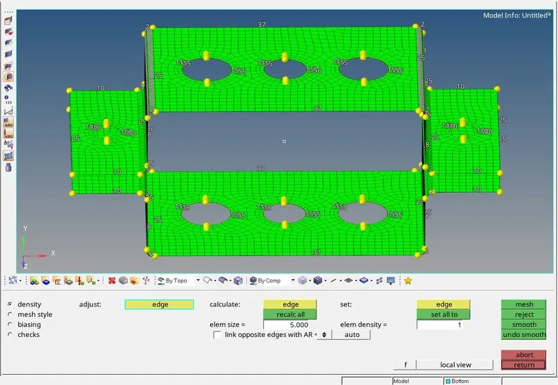
- Before meshing is done the washer splits are added for a more accurate mesh.
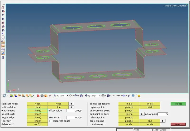
- A 2-D mesh with an element size of 5mm is created with quad elements. The number of nodes in the washer splits were also changed to have a uniform mesh around the holes.
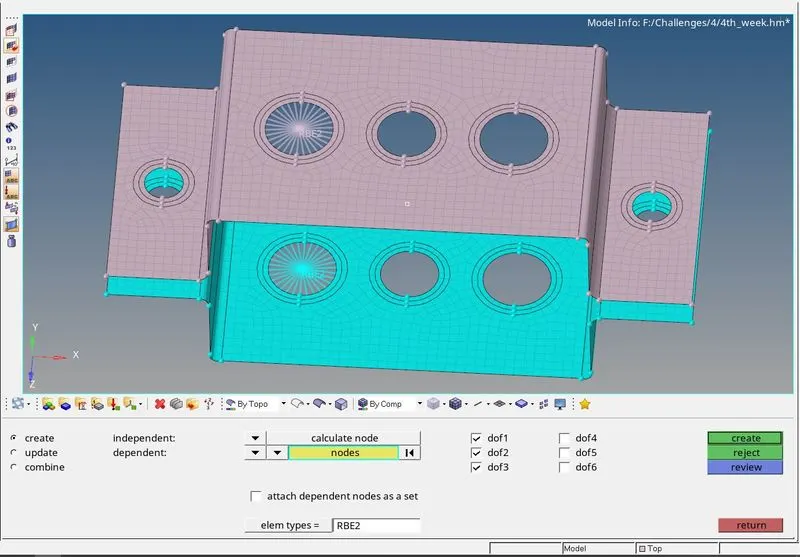
- Following this, the rbe2 elements are created with only translational dofs constrained. The nodes to be associated with the element should be selected. While creating the elements we have to check for the component to which it is associated and change the component if necessary.
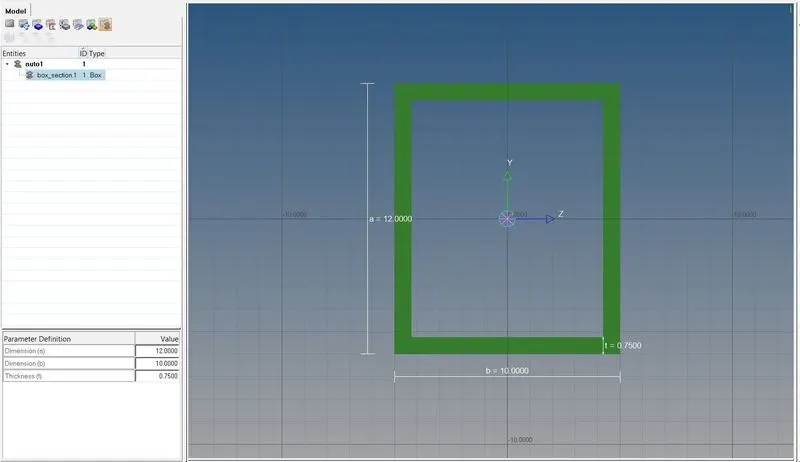
- The first element that has to be created is the rod element with a thin-walled box cross-section. To create the cross-section the HyperBeam window is used. The dimensions of the cross-sections are changed to the given dimensions.
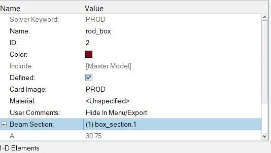
- A property for the rod element is created and the cross-section created is selected and the Card image is selected as PROD.
- To create the rod element the nodes between which the element has to be created have to be selected. The element type is selected to CROD and in the property, the property that was created with the thin-walled cross-section is selected.
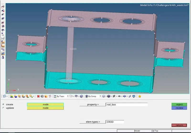
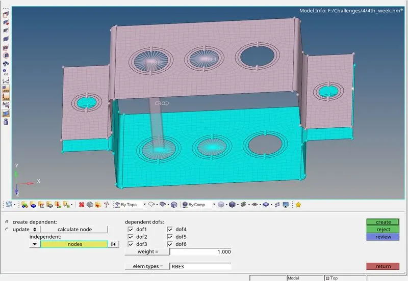
- For the next element rbe3 element with all dofs constrained are created.
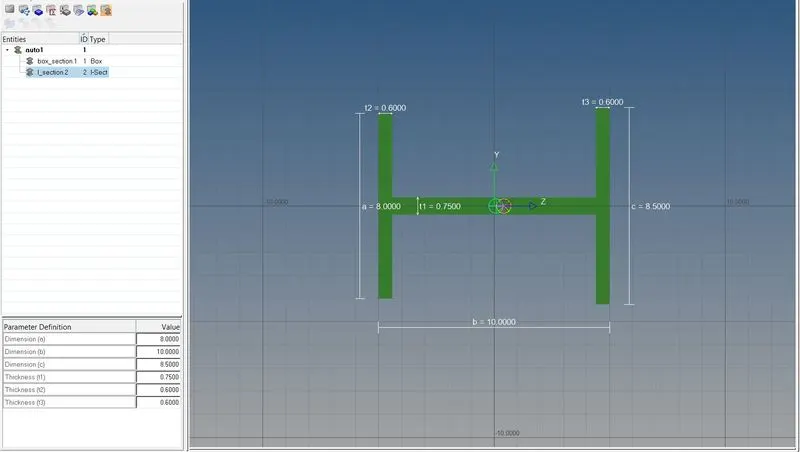
- Similar to how the thin-walled cross-section was created the I section is also created using HyperBeam and its dimensions are changed to the dimensions provided.
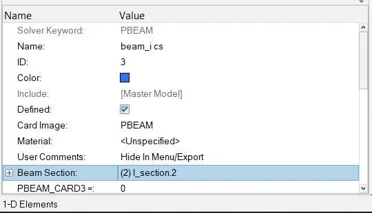
- Just as it was done for the rod element, a property is created for the beam element and the PBEAM is selected and the I cross-section that was created in HyperBeam is selected.
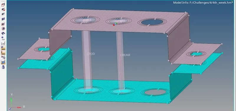
- To create the beam element the bar option in the 1D tools is used. The two nodes between which the element is to be created are selected and for its orientation, the three colored nodes are selected The element type is chosen as CBEAM and the property with the I-cross-section beam is chosen.

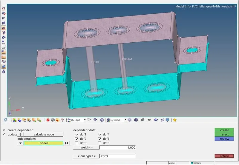
- For the bar element rbe3 with only x and y dofs constrained are created.
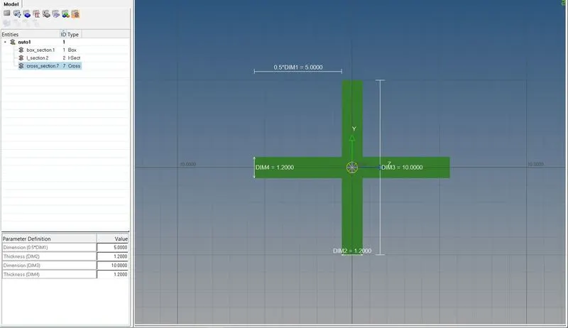
- Following this for the x cross-section, OptiStruct option is used and its dimensions are changed to the given dimensions.
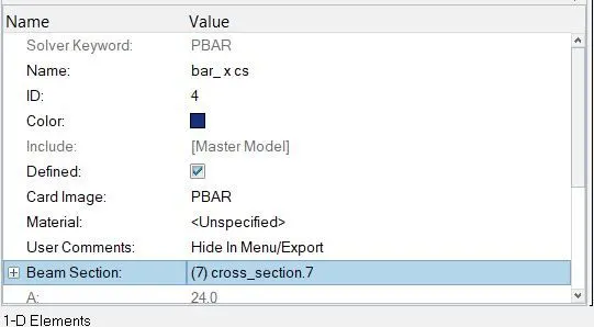
- A property is created for the bar element and PBAR is selected and the x cross-section is also selected.
- The bar element is created using the bar option and in that, the element type is selected as CBAR, and for the property, the property with the x cross-section is selected. The node selection is similar to the creation of the beam element.
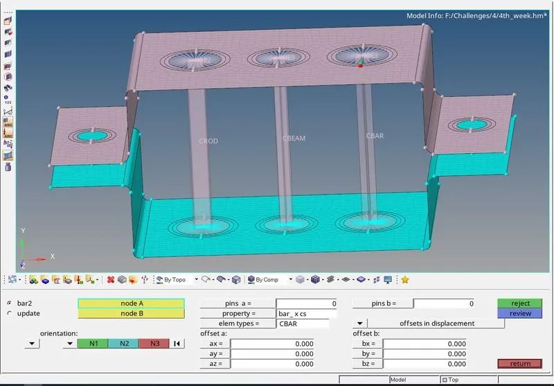
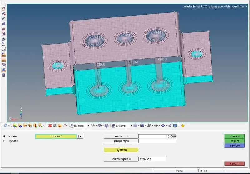
- The rbe2 is created for the masses to be applied on. The node on which the mass is to be added is selected.
- To create the spring elements the nodes between which they have to be created are to be selected.
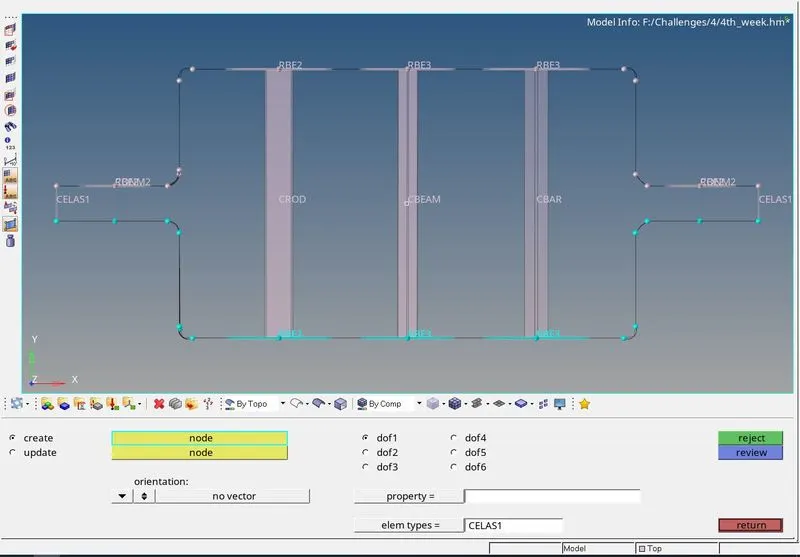
Result: The given model is meshed with an element size of 5mm and the 1D elements are created as per the instructions.
Final model: