Week 8-3D Tetra Meshing Challenge
OBJECTIVE
To mesh a solid component with different methods and by creating tetra elements without any Tet collapse error.
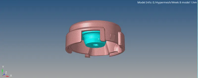
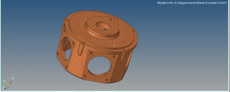
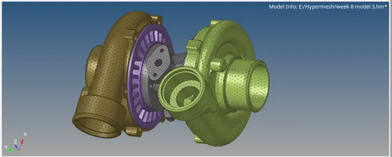
CAD MODEL IMAGE
PROCEDURE
MODEL 1
For this model we prefer to go with 2D surface meshing and by converting the 2D elements into 3D elements. at first, we have toggle the construction that match to the minimum length. After cleaning the geometry do surface meshing. Do Auto mesh with trias in the length of 5, min and max will be 2 and 7. So we can check the max and min error in the quality index. So now we can create a tetra mesh. Before doing tetra, we have to check the boxes in parameters as fill voids, smothering, fill midnodes and also set Tet collapse value as 0.150. And also set max tetras as 7.
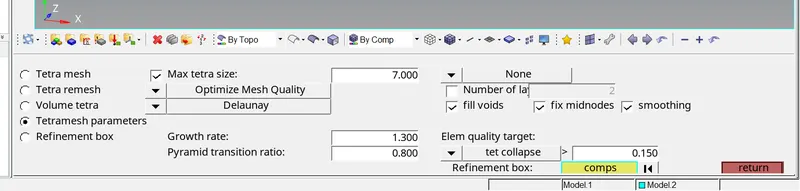
Now go to tetra mesh and select all the elements and mesh.
Check for the Tet collapse error in check elements.

Remesh the tetra here, tetra remesh<select 3D and 2D elements also. After remeshing again we have to check for the tet collapse error. Now I achieved a zero error in Tet collapse.
MODEL 2
This model will be meshed with quick tetra mesh, go to view<browsers<hyper mesh<utility. Here choose quick tetra and select the component and give the required values in the system. After completing mesh check for the tet collapse. To clear the Tet collapse remesh the tetra again and we can fix it.
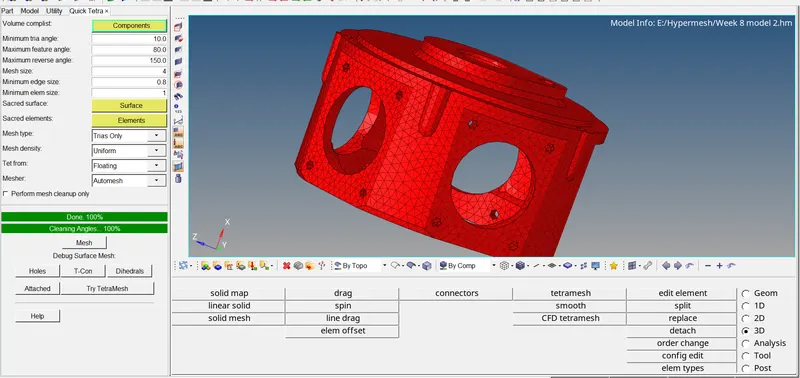
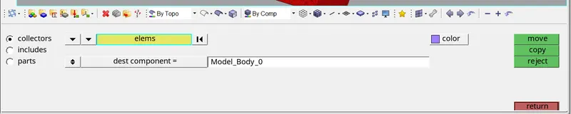
Here quick tetra will be organized by default in a separate collector. So, we can it to the parent component by using organize tool.
Model 3
For this assembly, when using the volume tetras (3rd method) it gives a more tetra issues and we can’t able to fix. To fix it took more time. So here we have 5 parts, for every part I tired with volume tetras but its not good. So, I moved with quick tetras, here we have a smaller number of tet collapse. So, I can fix it by remeshing the elements. I have a better mesh than the volume mesh.
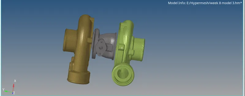
Also by comparing the mesh, with solid and without solid gives a less amount of errors. In surfaces we can find out a free edges and penetrating surfaces, so I deleted all the solids.
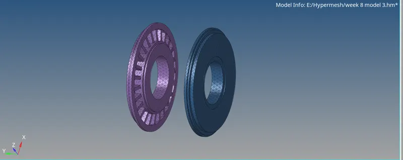
For these 2 parts I didn’t go with quick tetras, because where the part has the less length the feature capturing was not good. So, I did 2D surface meshing and convert it into tetras.
After the completion we can delete the 2D elements.
RESULTS
In this solid meshing the 2d to 3d convrsion gives a less error and the quick tetras, volume mesh gives the same amount of error in the part. andd quick gives a better mesh than the solid mesh. the quality of mesh can be achived in the 2d to 3d conversion.
FINAL IMAGE