Week 8:- 3D Finishing - Challenges 1
#1_3D Finishing:
The process through which a design is completely finished and ready for final simulation and 2D details is known as the 3D finish, as shown in the diagram below. When the design is finished, the nominality of each unit and hole is checked to make sure that everything can be installed quickly. The concentricity and size of the holes should be checked to verify that the various components can be put together easily. Fasteners are used for various holes and parts according to the size of the hole and predetermined colour codes. Simple holes are typically coloured violet, threaded holes are typically yellow, machined areas are typically cream, and dowel pin holes are typically coloured blue. After completing all of the preceding steps, the model is sent for simulation and 2D detailing.
#2_Following points to be considered while 3D Finishing of Design Takes place:
Nominality : All unit dimensions should be maintained nominal to facilitate easy assembly of the unit from a fixed edge.
Hole concentricity & hole sizes: All parts are to be checked for hole concentricity and to be confirmed for easy assembly while finishing the parts.
Machining area: The machining area in every part should be defined and the machining area should be highlighted by using standard color code.
Gaps checking: Proper gap should be maintained between units to avoid the clash between the different units.
Fasteners implementation: Fasteners should be implemented in all unit as per the requirement and load on the part.
#3_Rough Locators and its use:
A part called a rough locator directs the user where to lay the automobile panel on the pins. Both standard and custom parts are available for a rough locator. In the automation process, rough locators are utilised to find workpieces. When a person, group, or robot is working on a workpiece, "locating" refers to where you want the workpiece to be.
Rough locators help locate workpieces throughout the automation process. The desired location of a workpiece is referred to as "locating" while a person, group, or robot is working on it. The uniformity and quality of the finished product are directly impacted by the locating components' accuracy. These features of your setup are crucial because of this. It is sometimes referred to be a foolproof method. The rough locator stops the component from being loaded in the wrong spot. Since the rough locators are adjusted based on the angle of the pertinent panel, the part can only be loaded in the proper direction and orientation.
#4_Fundamentals of Rough Locator Designing:
Rough locators should be placed at the car panel,which it has to guide.
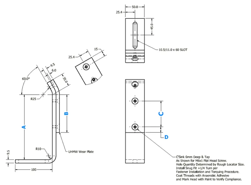
Rough locators should be placed in the same angleof the part edge with a min. distance of 2-5mm from the edge of car panel.
Rough locators should guide in the pin arresting direction.
Rough locators should start guiding the panel before 10-15mm to the start of pin engagement.
Rough locators should be designed with entry anglefor car part entry.
Rough locators should be designed with two slots to mount for easy adjustments.
The slot should be in the direction of car part guiding.
#5_Gun Study
In the automobile business, welding is a procedure that is frequently used, and standards for the welding process are constantly being improved. Welding is used to put together the sophisticated construction known as Car Body-in-White (BIW). Establishing the location of the spot welds is the first step before designing a welding setup. The weld spot distribution dictates the positioning and orientation of other crucial fixtures components like clamps and locators. The weld matrix and welding position are shown in the figure above, along with the spot welding tool that will be utilised.
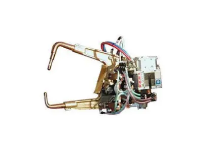
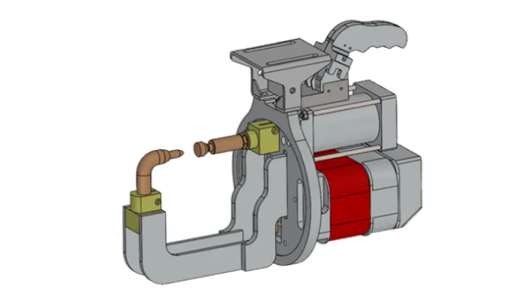
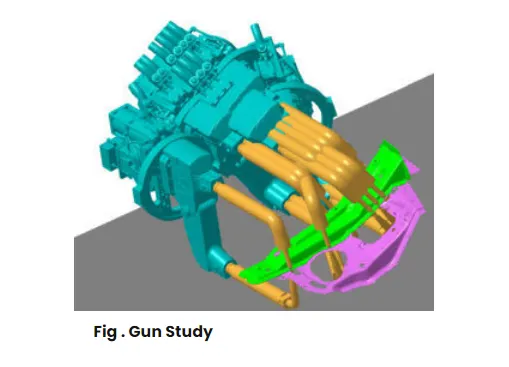
Weld spots will come in two varieties: geo weld points and respot weld points. In the first stretch, the geo weld locations are welded, and in the second stretch, the respot welded places are welded. Gun studies comprises learning about the weld gun, a portable device used for semiautomatic welding of parts and components. The weld gun will be used for the operation according on the part's size, thickness, and other factors. If the welding gun hits the fixture unit, the fixture is redesigned or moved, which validates whether the welding gun is falling or not. If the cannon hits the fixture unit, the fixtures are changed, but the weld spot locations are kept the same.
#6_Various points to consider while Gun Study :
Weld gun study is very time consuming process and presented below:
The points to be considered during the gun study are ;
The number of weld spots on the panel and the amount of time needed to spot each weld define the overall time needed to complete all of the weld spots. The axis of the weld spot in the direction of welding must be parallel to the weld surface. We can simulate each model's behaviour in the work cell over time if we have one or more device models and want to programme them. Each device's instructions are coded using sequences.
The sequence establishes how the devices will move, be used, and function. Based on the location of each tag point in relation to the home location, the type, speed, and acceleration of the motion can be used to determine the cycle time for each device connected to the sequence. In this way, the robot cycle time is correctly calculated. In order to make sure that the welding process is collision-free, a simulation is run once all of the devices have been sequenced.
#7_Pneumatic Routing:
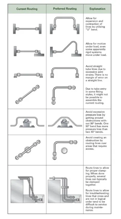
Pneumatic systems must be effective and leak-free. Sometimes they aren't because of improper tube line routing brought on by a lack of knowledge, a lack of planning time, or even both. Planning the route of tube lines takes time, but it can be quite beneficial, especially in systems that are complex. After sizing the tube line and choosing the required fittings, routing should be designed as the following stage of system design.
Clamping should be considered when designing routing. Proper clamming follows logically from appropriate design. It is frequently possible to clamp together many lines. Think on maintenance and troubleshooting: concentrate on logical design and prevent crossed lines. Reduce the possibility of users climbing or standing on plumbing by designing the tube line routing.
#8_Solenoid Valve:
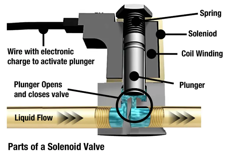
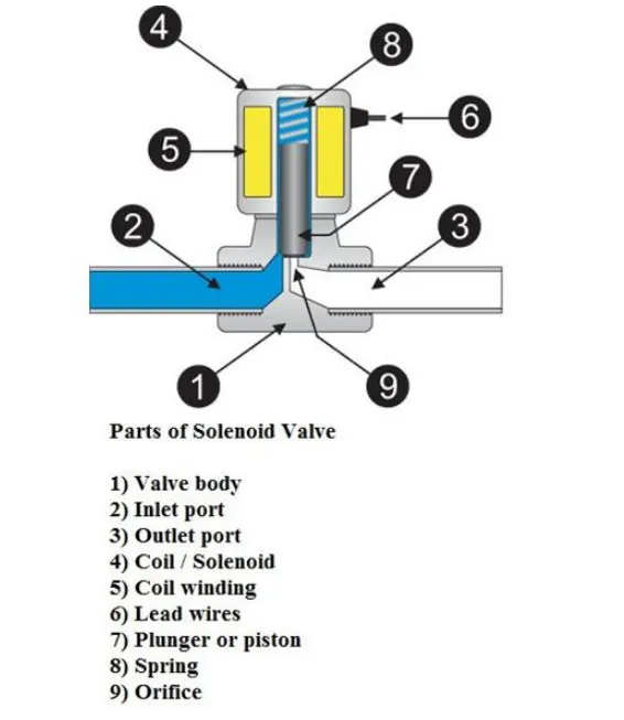
By opening or shutting an aperture in the valve body, a solenoid valve regulates the flow through a valve. When the coil is actuated, a plunger raises or lowers the aperture within a sleeve tube, opening or closing it. A coil, plunger, and sleeve assembly make up solenoid valves, as shown in the diagram below. An electromechanical valve is a solenoid valve. Different solenoid valves operate with different electric current characteristics, magnetic fields of varying strengths, fluid regulation mechanisms, and fluid characteristics. There are several different types of mechanisms, such as rocker actuators, plunger-type actuators, and linear actuators.
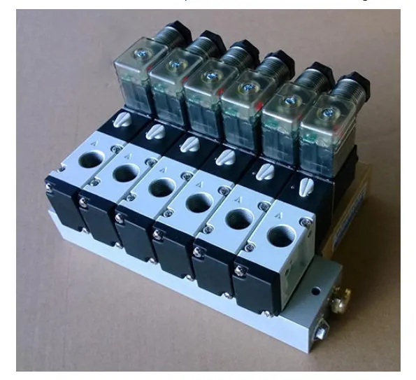
Several solenoid valves can be grouped together on a manifold. Since they may shut off, release, dose, distribute, and mix fluids, solenoid valves are the most often used control elements in fluidics. Fast and secure switching, excellent dependability, prolonged service life, medium material compatibility, low control power, and a compact design are all features of solenoids.
#9_Valve Bank:
A collection of solenoid valves is known as a solenoid valve bank. The valve bank will consist of a common inlet port, a single servo line to each pneumatic valve, and separate vent channels for each solenoid. A collection of unique valves that control various consumers is known as a valve bank. The BA directional valve bank is made up of numerous valve sections. Compact control blocks can be created using these components. The valve is actuated, allowing servo air to enter the servo port, by selectively activating the matching solenoid. In order to restore the valve to its fail-safe state, the solenoid is de-energized by opening the valve's servo port to ambient air. It is simple to choose between two and six solenoid valves thanks to the design architecture.
#10_Sensors:
A sensor is a device that recognises or quantifies a physical characteristic and then logs, displays, or reacts to it. The PLC executes the subsequent operation after receiving the signal from the sensors. The sensor, an extremely delicate and easily damaged component, is protected by a sensor cover.
Since they allow for intelligent and highly automated devices, sensors are crucial in the industrial automation business.
These can be used to detect, evaluate, measure, and process a variety of changes that take place in industrial locations, such as changes in position, length, height, appearance, and displacement.
These sensors are crucial for anticipating and preventing a variety of future events as well as for meeting the requirements of several sensing applications.
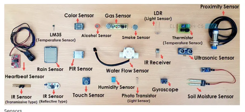
#11_Types of Sensors:
There are many different types of sensors, the main categories are;
Position Sensors:There are many varieties of position sensor; linear, rotary, contacting, non-contacting and use a variety of different technologies. Position sensors are used to measure and monitor the position or displacement of an object.
Pressure Sensors: Pressure sensors are often split into the following two categories; Pressure transducers and pressure switches. The main difference is that pressure transducers give accurate feedback on real-time pressure and pressure switches have a set limit which causes them to switch
Temperature Sensors: Temperature sensors are used to measure and monitor temperature, whether this is the main variable requiring measuring or a secondary variable which requires monitoring as a safety precaution within another application.
Force Sensors: They are used to measure various types of force, the main one being weight. Load cells are used in all types of scales; from bathroom scales to counting scales, industrial scales, truck scales, hopper scales and everything in between.
Vibration Sensors: A vibration sensor is a device that measures the amount and frequency of vibration in a given system, machine, or piece of equipment. Those measurements can be used to detect imbalances or other issues in the asset and predict future breakdowns.
Piezo Sensors: A piezoelectric sensor is a device that uses the piezoelectric effect to measure changes in pressure, acceleration, temperature, strain, or force by converting them to an electric charge.
Fluid Property Sensors: Relying on tuning fork technology, the sensor monitors the direct and dynamic relationship between multiple physical properties to determine the quality, condition and contaminant loading of fluids such as engine oil, fuel, transmission and brake fluid, hydraulic and gear oils, refrigerants and solvents.
Humidity Sensors: Humidity sensors work by detecting changes that alter electrical currents or temperature in the air.
Strain gauges: A strain gauge is a type of electrical sensor. It's primary use is to measure force or strain. The resistance of a strain gauge changes when force is applied and this change will give a different electrical output.
Photo Optic Sensors: Photoelectric Sensors detect objects, changes in surface conditions, and other items through a variety of optical properties.
Flow and Level Switches: Flow switches are used to monitor and control the flow rate of fluid within an industrial process system. A level switch is an electrical or mechanical method for measuring the level of a liquid, powder, or granule material.
#12_Basic Fundamentals to design sensor unit:
The sensor unit detects the automotive panel with the use of electrical sensors.
The signal from the sensors will be sent to the PLC, which will then be used to control the next phase.
Sensors are used to assess the presence or absence of a panel or component.
It should make it easier to avoid human mistake.
The number of sensors should ideally be equal.
In proportion to the number of panels in an assembly, at least 14 sensors should be used if the assembly has 14 panels.
Sensors should ensure the operator's safety.