Week 8:- 3D Finishing - Challenges 1
1) What do you understand by the 3D finish process?
3D finishing is thee step done before sending the part for final simulation. The part should be checked for all proper clearances and representing the machining sides of a part and also the hole segregation by applying standardized colour codes.In this process the part is checked with hole concentricity ,designing of rough locators for guiding the panel so that the design is completely frozen and ready for the simulation and 2D detailing post that.
For example we use dark blue for dowel holes, cyan for open holes and yellow for threaded holes. This helps the person looking at the design to identify what type of holes they are such. All these steps are done in the 3D finishing stage.
2) What are the points need to be taken care of while finishing the design?
The points that need to be considered while doing the 3D finishing stage are:
- Hole concentricity
- Hole sizes
- Nominality
- Machining Area
- Colouring Standard for the Holes
- Pneumatic Lay-outing
- Checking for Gaps
- Implementation of Fasteners
- Avoid clashing between different components
- Splitting of the mylars as per the panel profile
- Proper renaming of the parts as per the standard and proper reordering of the tree.
3) What are rough locators & what is their use?
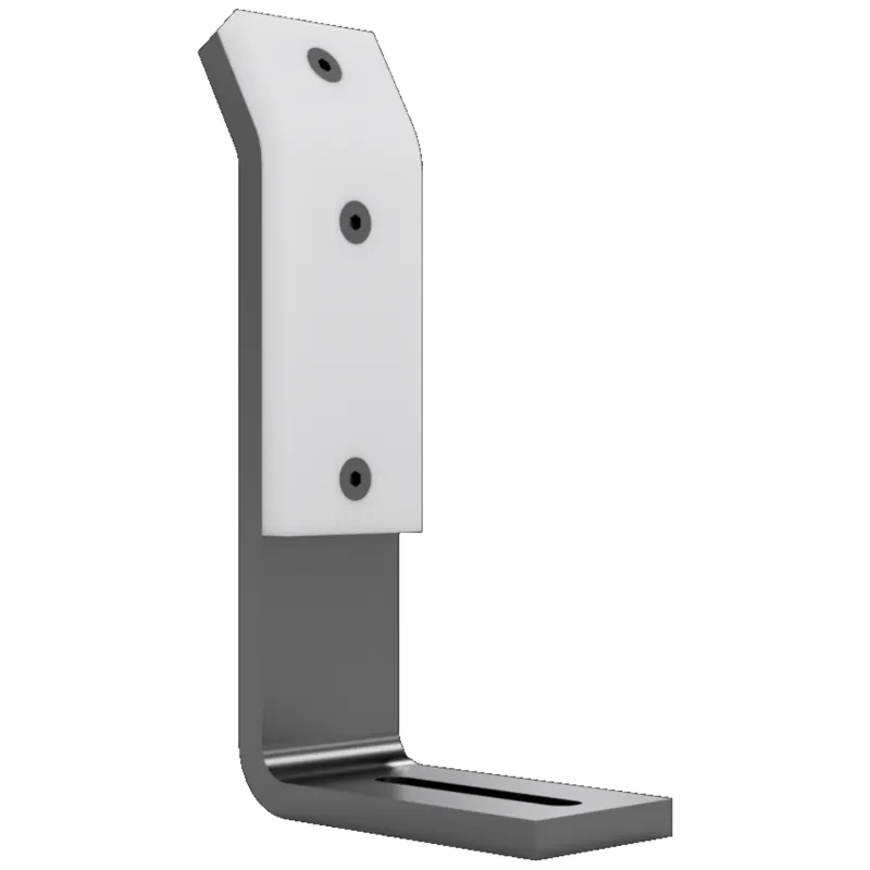
Rough locators are basically used where manual loading of panels are to be implemented on the fixture. They help in guiding the panels in the correct position and orientation so as to avoid any errors in the assembly.
Rough locators assist in following the method of Poka-Yoke, which is a japanese technique. Poka-Yoke ensures that the right conditions exist before a process step is executed, and thus preventing defects from occurring in the first place. Where this is not possible, Poka-Yoke performs a detective function, eliminating defects in the process as early as possible. Its purpose is to eliminate product defects by preventing, correcting, or drawing attention to human errors as they occur.
Rough locators are usually made of mild steel or other similar metals.
4) What are the points you need to consider while designing a rough locator?
The considerations to be made while designing the rough locators are:
Height of the rough locator should not be more than the permissible ergo height of the fixture.
Rough locators should have adjustment in the direction of the guiding plane.
2 mm gap is to be maintained between the rough locator and the panel at the time of design and an additional adjustment of 5-10 mm should be provided in the positive or negative direction of the guiding plane.
The entry point/top most point of the rough locator must be 10-15 mm above the panel surface.
Rough locators can be of different shapes and design, it can be a rod or flat type depending on the standards and design requirements.
5) what is the gun study process?
In the weld gun study, we decide on the type of weld gun that is used and we check if it is feasible for the current fixture design. This would involve inserting the model of the gun into the design and fixing at the pre mediated spots for the welds. All the guns are brought in to the assembly and the a check for the possible clashing of the guns is done. The guns are adjusted in such a way to avoid the clashing in the 3D model.
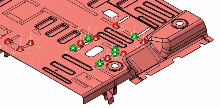
The next step to check after checking for the clashing of the guns is to study if the weld points are within the reach of the gun since we already know the limitations of the robot arm to which this gun is attached to.
Once this is also checked out, we must finalise on the weld spots and the positions of the respective weld guns.
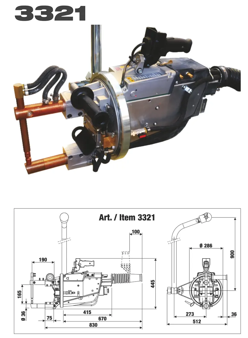
Spot welding guns are normally designed to fit the assembly. Many basic types of guns are available, the two most commonly used being the direct acting type, generally known as a C-type gun, where the operating cylinder is connected directly to the moving electrode, and the X-type where the operating cylinder is remote from the moving electrode, the force being applied to it by means of a lever arm. C guns are generally the cheapest and the most commonly used. There are many variations available in each basic type with regard to the shape and style of the frame and arms, and also the duty for which the gun is designed with reference to welding pressure and current.
6) What are the points needed to consider during the gun study?
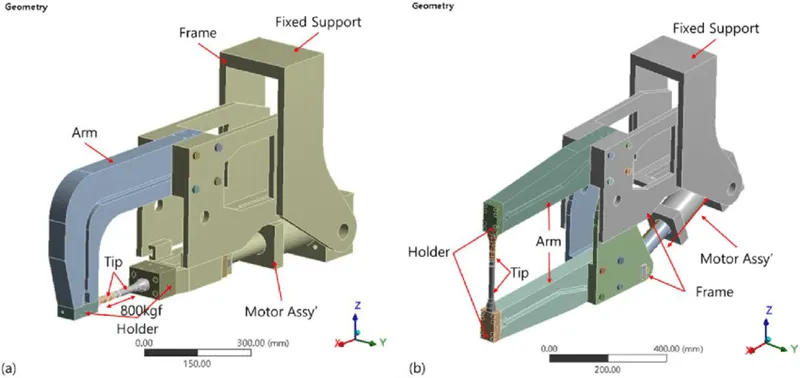
Since the weld study is such a time consuming and extensive process, we must follow these points when carrying it out
- The number of weld spots for the panel
- The time duration for each weld
- The total time required to complete all the welds on the panel
- The axis of the weld spot must be normal to the weld surface
- If there are multiple weld guns, we generate a sequence or order for the oepration of each gun. This defines when each gun will function and at what point and following which weld gun. By running a simulation on these sequences for all the gun we can calculate the robot cycle time
- The last point is to do a simulation check to see that the entire assembly is completely collision free.
7) What is pneumatic routing?
A pneumatic system is any mechanical system that is operated with the help of air. The pneumatic systems are generally open loops systems and are used for low pressure output applications. A hydraulic system is used if there is a need for a high pressure output. It is much cheaper than a hydraulic system when it comes to initial costs but the maintenance.
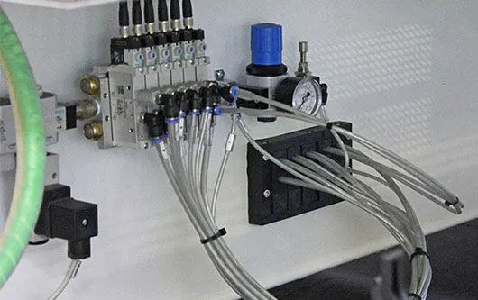
8) What is the solenoid valve?
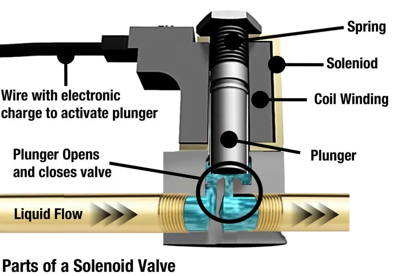
A solenoid valve is used to actuate the air flow in cylinders as per the sequence through a manual or PLC operated system. A solenoid valve consists of a solenoid and a valve body. The solenoid has an electromagnetic inductive coil around an ferromagnetic core at the center of it called the plunger. When a current is passed through the solenoid, the coil gets energized and generates a magnetic field which creates a an attraction with the plunger causing it to overcome the tension of the spring and enabling it to move to its open or closed position. In the rest position the plunger closes the orifice and when a current is passed through the magnetic field exerts an upward force on the plunger thus opening this orifice.
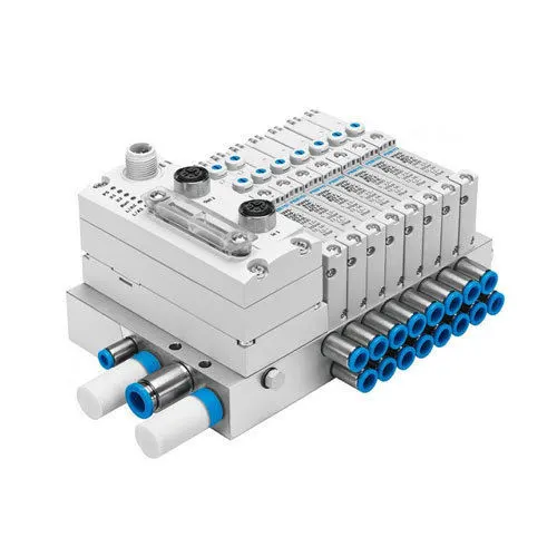
9) What is the valve bank?
A valve bank is a system in which 'n' number of solenoid valves are mounted in order to maintain one common inlet and outlet of air to all the valves. Valve banks are mostly mounted on the fixtures side or onto the base plate depending upon the various condition.
Valve banks are positioned in such a way that there is an ease of accessibility for maintenance purposes. It should be ensured that valve banks are properly covered with a sheet structure to avoid any damage to it as it houses all or most of the valves required for the functioning of the fixture in it.
The major suppliers for valve banks and the valves are Festo, SMC, CKD, Janatics and the selection of these components are done as per the given requirements & data sheets available on the catalogue or websites.
10) What is a sensor & briefly explain about its application in automation?
A sensor unit is a unit in the fixture that is designed to sense if the panel is present or not on the fixture by using electrical sensors. These signals from the sensor is fed to the controller (PLC) and the next process is executed depending on what the output of that signal is. If the sensor sends the signal stating that the panel is present then the automation process moves forward to the next step and if not, the process will not go ahead. The number of sensors in a fixture will be roughly equal to the number of components placed on the fixture.
Sensors can help us achieve better quality and decrease the number of errors that could occur such as placing the panel on the fixture in the wrong orientation or it can detect if a panel or part is missing in the assembly, etc.
11) What are the types of sensors?
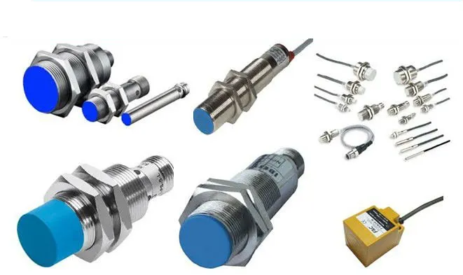
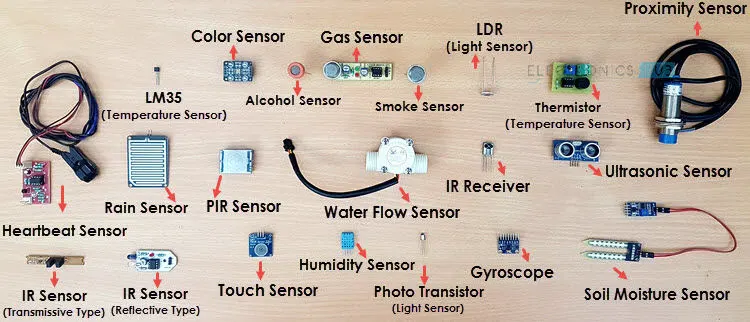
There are few different variations of sensors used in the market and they are:
- Proximity Sensors: Proximity Sensors detect an object without touching it, and they therefore do not cause abrasion or damage to the object. Devices such as limit switches detect an object by contacting it, but Proximity Sensors are able to detect the presence of the object electrically, without having to touch it.
- Laser Sensors: Laser sensors generally work well in a dirty environment since the focused light can “burn” through dust. The focused beam also enables long sensing distances, and detection of small objects or targets through small openings. Laser sensors are often used in process monitoring and closed-loop feedback control systems
- Photoelectric Sensors: A photoelectric sensor is a device used to determine the distance, absence, or presence of an object by using a light transmitter, often infrared, and a photoelectric receiver. They are largely used in industrial manufacturing.
12) What are the fundamental points needed to be considered while designing or selection of sensor?
The fundamentals of a sensor unit design is as follows:
- Every single loose panel which are being welded in a tool should sense.
- Each panel should be sensed by 1-2 sensors depending on the size of the panel. If more than one sensor is being used then the preferred placement of these sensors would be at diagonal ends of the panel.
- Every sensor should be mounted in a 3-direction adjustable way.
- Selection of the sensors can be easily done by referring the catalogues or data sheets available on the company website.