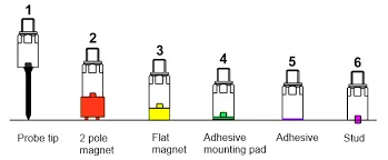
Week 8:- 3D Finishing - Challenges 1
1.
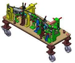
a)while finishing the design the nominality of holes is checked which ensures easy assembly of all the units.
b)the hole concentricity and hole sizes are checked which ensures the easy assembly of different parts.
c)the gaps between the different units are checked to ensure the proper individual working of different units.
d)designed the rough locators which led to load a panel in design orientation,
e)designed pneumatic layout for pnematic connection.
f)a gun study is major area most important for 3D finishing.
2)
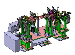
a)all parts hole concentricity should be checked and confirmed for easy assembly while finishing the parts.
b)The machining area in every part should be defined the machining area should be highlighted by using standard colour codes.
c)nominality=all units should be maintained nomina to facilitate easy asembly with other.
d)Holes
Dowel hole=Blue.
threading=yellow.
C.B=skyblue.
3)
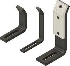
a rough locator is a part used to guide the panel to locate the car panel on pins .the rough locator can be a stand.
b.rough locator can also be a poke-yoke to ensure mistake proofing.
c.rough locator are used for loating the workpiece for automation process.
d.rough locator ensures proper loading of the parts.
e.rough locators are set according to angle of respective panel or components.
4)
a.rough locator should be places at edges of car panel which it has to guide.
b.rough locators has to be placed in the car panel of the car part edge with minimum distanc of 2-5 m from edge of car panel.
c.rough locator should guide the panel in pin arresting direction.
d.rough locator should start guiding the panel before 10-15 mm to the start of engagement.
e.rough locator should have the angle of 30-45 degrees.
f.rough locator should bedesigned with two slot for easy mounting.
5)
welding is predominately used in automobile industries and requirements for fixture that ease the welding process is a continous development .car body in white is a complicated steel structure including 300-500 sheet metal with complex shape are assembled bt means of welding in a high rhytm .the foremost structure taken before starting before starting the design of welding fixture is to arise at spot.
the location and orientation of the critical units of the fixtur including clamp and locator are decided on weld spot distribution.the weld spot for front door inner side panel bracket assembly are located as shown with respect to panel.
the device used to make spot welding on the panel is called weld gun.
the gun may differ depending upon the application fixtue wiil be designed by considering weld spot distribution of the panel.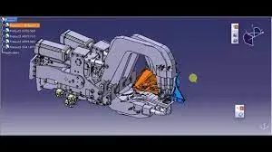
6)
a)The axis of weld spot along welding direction must ne normal to the weld surface.
b)The no of weld spots for the panel the time required to spot each weld and total time required to complete assembly of weld spot.
c)if we have one or more models and want to program the behaviour of each model in the work piece can be simulated over the time .instruction for each are coded by giving sequence of operation.
d)after sequencing all the devices with collision check.make sure that welding operation is collision free.
e)There should be adequate space between the weld gun and fixture units.
f)make changes in fixture units.
7)
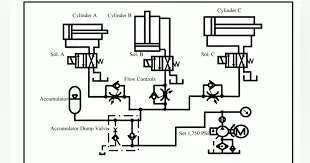
pneumatic systems should be efficient ,leak free.sometimes they are not because of improper tube line routing.it may be because of eithe lack of knowledge or incorrect cut on planning time or both.
what can go wrong if routing is not done properly .all kind of thing from not being able to accept for inefficient maintenance all the use of leaking connection,inefficient poor tube routing can create unintended issues that need to be addressed .the ounce of planning is more than pound of troubleshooting.
planning tube line routing is an time investment.but it can culminate into big ROI.especially for complex systems.during the system routing should be developed .the next step is routing of the tube and selecting approriate fittings.
leave fitting joints as accessible as possible .In accessibel joints are difficult and time consuming to assemble,tighten and service.
use software for time consuming operations like pressure-drop.
employ U- bends to all line contraction and expansion.
Include ofseting bends to allow for motion under load regarless how rigid the system seems.
The tubes should be precisely machined to reduce flow contriction and pressure drops.
design the tube line routing reduce the likelihood of user,feed climbing or othe operations.
8)
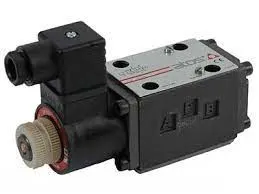
solenoid valves are electrically activated typically used to control the flow of air or fluid.in fluid power system used in both pneuatic fluid power system the spool or poppet design of most solenoid valves makes used for various fluid and power operations.
the spool or poppet of the valve connects to ferrous metal plunger which typically spring centre of the assembly.the plunger slides with core tube of non ferrous metal .itself surrounded by a coil of electric wires.
the coil exists with the voltage of 12-48 kv to 110-220 Vac.when power is send to the valve which guides for further operation.
spool solenoid valve consists of machined spool.
solenoid valves for either hydraulic or pnuematic operation are available for monitoring.
9)
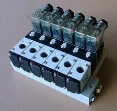
valve bank is cabinet consisting of array of valves into it.
it has a common supply line of certain pressure
the valve bank each solenoid has a peculiar typical operation for so the solenoid operates accordingly for the operation.
on the solenoid bank each of the solenoid separately controls the feed of high pressure servo air to single pneumatic valve.
two stage solenoid is designed for faster response time.
10.
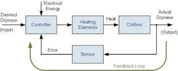
automation syste is closed loop system system which has varied controls on it like the sensors,control unit,servo drives on it.
automation system ensures seamless operaton of the the process .
if error or deviation is recorded from control program then the error is mitigated properly.
the servo system drives the feeding mechnism.
11.
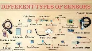
types of sensors.
alight sensors.
1.IR sensors.
2.photodiode.
3.LDR.
2Temperature sensor.
thermistor.
thermocouple.
3pressure/force/strain.
stress gauge.
load gauge.
4position sensor.
potentiometer.
encoder.
5.Hall sensor.
6.flex sensor.
7.sound sensor.
8.ultrasonic sensor.
9.touch sensor .
10.PIR sensor.
11.Tilt sensor.
12. gas sensor.
12)
1 sensor mounting should be provided at desired location and dimensons of the sensor from make should be properly accessed.
2.sensor should have 3 way adjustment provision.
3.sensor location layout should be systemitally planned .
4.sensor location should be in proper location so that it will not create in hindrance in operation.