Week 8:- 3D Finishing Challenge 2
Perform 3D finish and create Rough locators for the Assembly design created for the challenge on week 7
Introduction:
3D finishing is thee step done before sending the part for final simulation. The part should be checked for all proper clearances and representing the machining sides of a part and also the hole segregation by applying standardized colour codes.In this process the part is checked with hole concentricity ,designing of rough locators for guiding the panel so that the design is completely frozen and ready for the simulation and 2D detailing post that.
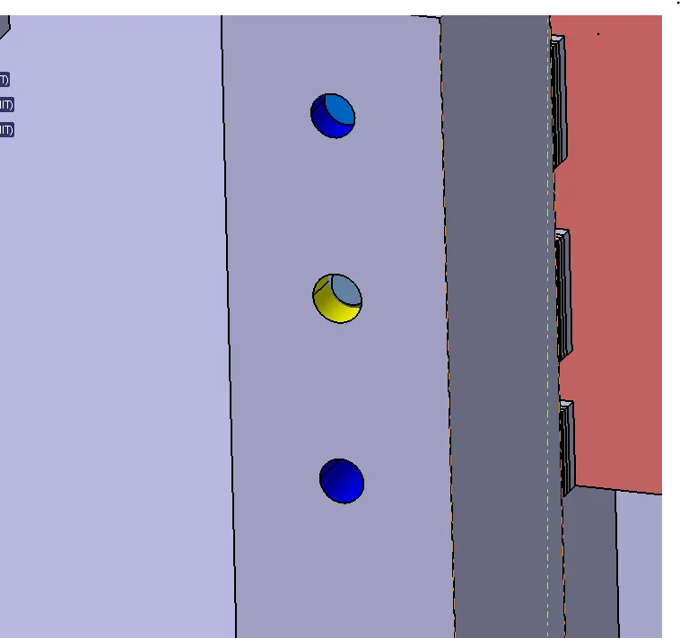
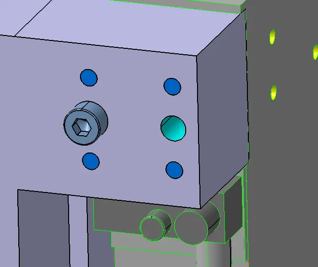
For example we use dark blue for dowel holes, cyan for open holes and yellow for threaded holes. This helps the person looking at the design to identify what type of holes they are such. All these steps are done in the 3D finishing stage.
There are certains steps undertaken to finalise the 3D finishing of a model and they are as given below
- Hole concentricity
- Hole sizes
- Nominality
- Machining Area
- Colouring Standard for the Holes
- Pneumatic Lay-outing
- Checking for Gaps
- Implementation of Fasteners
- Avoid clashing between different components
- Splitting of the mylars as per the panel profile
- Proper renaming of the parts as per the standard and proper reordering of the tree
1) Hole Concentricity
All holes were measured to maintain concentricity
2) Hole Sizes
All dowel pin holes were kept at 6mm while the the open holes for the screw was maintained at 9mm for all parts except the base of the riser where it was kept at 11mm. The threaded holes were maintained at M8 for all the holes except the ones the ones on the base unit for the risers which were kept at M10
3) Nominality
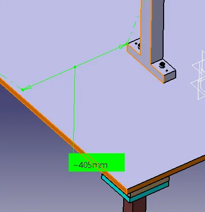
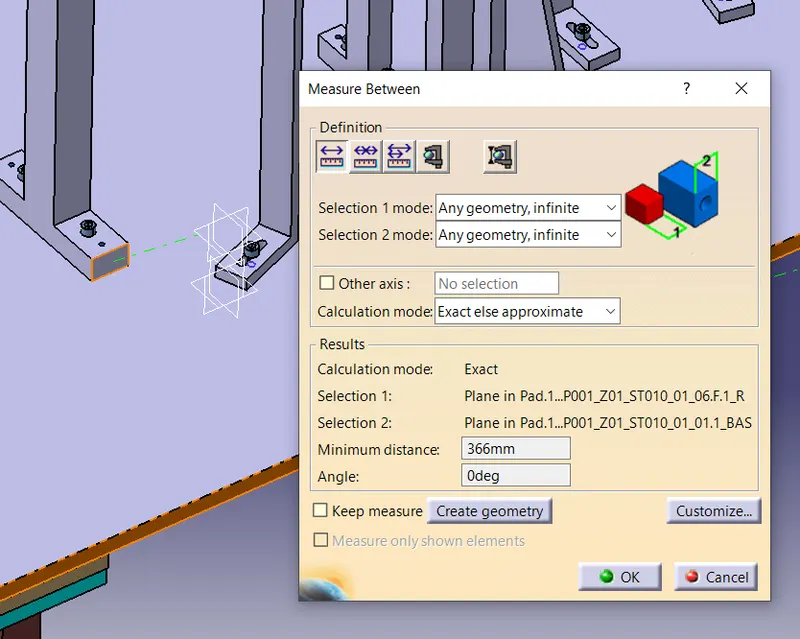
Nominality is maintained by measuring each unit ot the edge of the base unit and keeping it at whole numbers or with a decimal of 0.5 as seen below
4) Machining Area
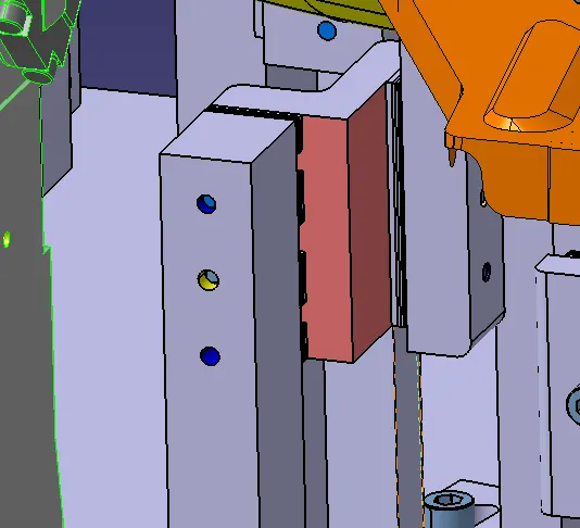
The surfaces that are meant to be machined are marked with a shade of red to notify that particular surface has been machined. The image belows shows an example of this machined surface
5) Colouring Standard for the Holes
The holes in the model have been coloured as per the required standard, so as to let the cutomer know what kind of holes they are.
The dowel holes are made to be of a dark blue shade while the open holes are cyan in colour. The threaded holes are yellow and this standard has been observed throughout the entire model as can been seen in the images below.
6) Checking for Gaps
All gaps between the various units have been checked and the necessary gaps were maintained as per the standards.
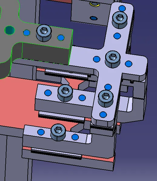
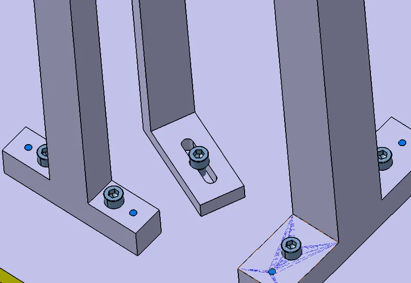
7) Implementation of the Fasteners
All the required holes were provided with the necesary fasters. The thread dimensions used throughout the model is M8 of metric thick pitch except the screw used for to fasten the risers, these were of M10 metric thick pitch.
8) Avoid clashing between different components
All units were checked, spaced out and oriented well enough to avoid any sort of clashing betweens components.
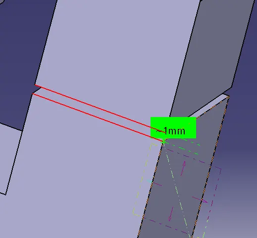
9) Splitting of the mylars as per the panel profile
The splitting of the mylars as per the panel profile has been observed and a gap of 1mm has been ensured between the clamp and rest mylars.
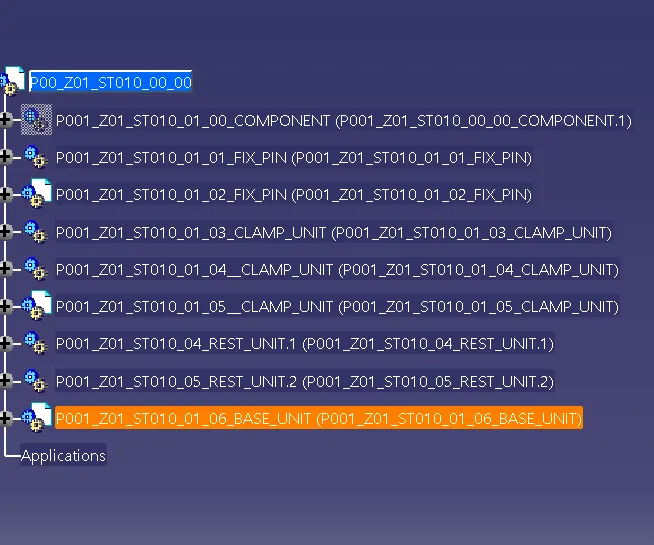
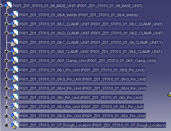
10) Proper renaming of the parts as per the standard and proper reordering of the tree
The renaming and reordering of the tree has been done as per the standard and the images below signfies this
Conclusion:
THe 3D finishing has been done and all the steps involved have been verified and the design is now completely frozen.