Week 8:- 3D Finishing Challenge 2
Aim : To perform 3D finish and create rough locators for the assembly design.
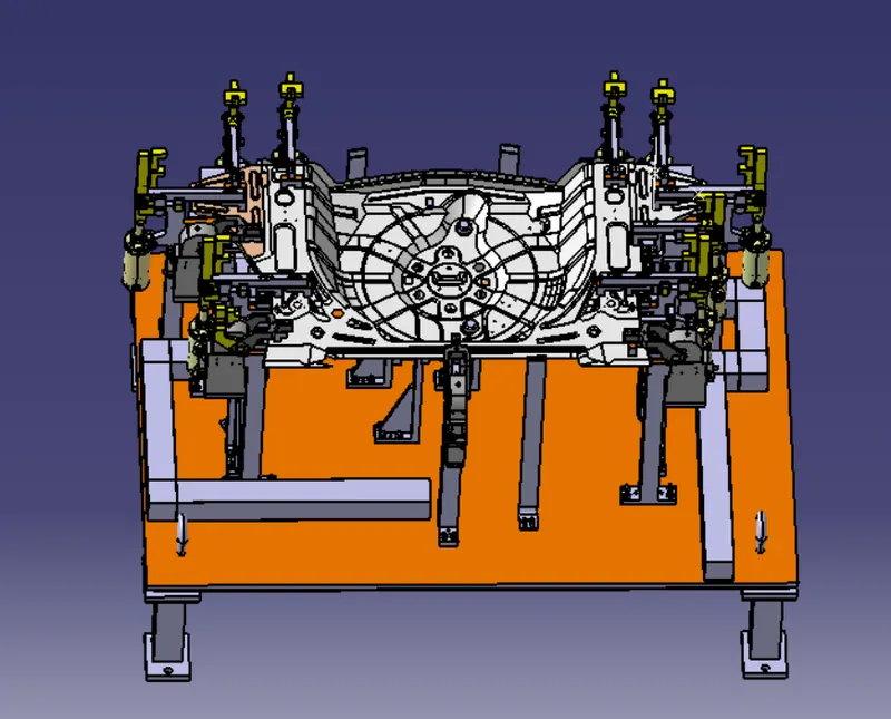
3D FINISHING :
3D finishing is a process where the design is being completely finished and ready for final simulation and 2D detailing.
- While finishing the design the nominality is checked which ensures the easy assembly of all the units.
- The hole concentricty and hole sizes are checked which ensures the assembly of different parts.
- The gaps between the different units are checked to ensure the proper individual working of different units.
- Design the rough locators, which helps to loading a panel in correct orientation.
- Design the pneumatic layouting for pneumatic connections.
- Gun study is major and msot important part in 3D finsishing.
- Selecting of sensors, solenoid valves as per the requirement and implementing in design.
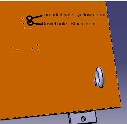
- Fasteners are implemented as per the hole size and the standard colour codes as per the customer requirement are applied to differentiate the type of hole whether its dowel hole, threaded hole or clearance hole.
- Renaming of the assembly and the part is done to give every part a different identity so everyone can identify in which assembly this part is going to be fit.
- After doing all these things the model is sent for final simulation and 2D detailing.
Points need to be taken care while finishing the design
1. Hole concentricity and hole sizes :
Concentricty of a hole refers to the tolerance allowed for the deviation between the location of the entrance and exit of a hole and hole sizes are checked for easy assembly while finsihing the parts.
2. Machining area :
The machining area in every part should be defined and the machining area should be highlighted by using standard colour code. Machining is to be done on parts to properly mount with mating parts. Machining only on desired faces reduces cost and save time and also machining increases accuracy of dimension. So before going to simulation or detailing machining area should be defined.
3. Nominality :
All units dimension should be maintained noimnal to facilitate easy assemble of the unit.
4. Holes colouring standard :
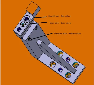
In a 3D finish hole colouring should be done because it helps to identify what type of hole it is. It depends on customer standards. Customer specific colour like : Dowel hole should be given bluie colour. Threaded hole should be coloured with yellow. Counter bore, open hole should be given cyan blue colour.
5. Pneumatic lay outing :
Pneumatic layouting is collection of different pneumatic pipes which work as a inlet to the pneumatic cylinder. It should be done properly for proper functioning of the units.
6. Gaps checking :
The gaps between the different units are checked to ensure the proper individual working of different units.
7. Fasteners implementation :
Fasteners should be implemented in all the units as per the requirement and load on the part.
8. Avoiding clash between different parts :
Proper gap should be implemented in all units as per the requirement and load on the part.
9. Mylar splitting as per panel profile :
Mylar splitting as for panel profile should be confirmed while finishing the design.
10. Proper renaming of parts or assemblies as per the standards :
Proper renaming of parts and assembly should be done while finishing the design and hence we can identify each and every part easily with unique identification.
ROUGH LOCATORS :
- A rough locator is a part designed to guide the panel, to locate the car panel on to the pins accordingly. A rough locator can be of standard part or a make part.
- Rough locators also work as Poka yoke. Poka yoke is a Japanese concept used for mistake proofing.
- Rough locators are also used to help to locate the work pieces in the automation process. Locating refers to the desired location where you want the workpiece to be when it is getting worked on either by a person or a team or a robot.
- The accuracy of the locating components directly affects the consistency and how the final product will come out. This is why these components are essentials to our setup.
- It can be also called as fool proofing method. Because without rough locator the part cannot be loaded in correct position.
- The rough locators are set accordingly to the angle of the respective panel and hence the part can be loaded in a defined direction and orientation only.
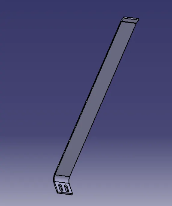
Image : Rough Locator
Points Needed to consider while designing a rough locator :
- Rough locator should be placed at the edges of the car panel, which it has to guide.
- Applicator has to be placed in the same angle of the car part edge with a minimum distance of 2-5 mm from the edge of the car part.
- Proof locator should guide the panel in pin arresting direction.
- Rough locator should start guiding the panel before 10 to 15 mm to the start of the pin engagement.
- Applicator should be designed with entry angle for the car panel. Generally, it ranges between 30-45 degree.
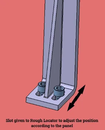
- Rough locator should be designed with two slots to mount the easy adjuystment.
- The slot should be in the direction of car part guiding.
PNEUMATIC ROUTING :
- Pneumtic system - System operated with air.
* Open loop system
* Generally used for low pressures
* Generally delivers less force compared to hydraulic system.
* Cheaper compared to hydraulic for basic cost. But compressor running cost is more.
- Pneumatic system is more preferred than hydraulic in BIW welding fixture.
- All toggle clamp, pin cylinder, slides are operated via pneumatic. Generally cylinder are designed to operate max. pressure 12-13 Bar.
- As it is expensive and difficult to maintain 10-12 Bar in shop floor it is preferred to design pneumatic system at 6 Bar pressure.
- Proper pneumatic lay-outing or routing is very much important to be shown in design, as it helps in describing the best possible way to keep all pneumatic pipes neat & away from welding spatters which can cause wear or tear of pneumatic pipes.
- In pneumatic lay-outing all pipes from cylinders are shown connected to valve banks and passes through a safety box like structure.
- Various major suppliers for pneumatic items are SMC, Teunkers, Festo, CKD etc.
GUN STUDY :
Welding is predominantly used in automobile industries and requirements for fixtures that ease the welding process is a continuous development task in any industry. Car Body-in-White (BIW) is a complicated steel-structure including 300-500 sheets with complex shape and are assembled by means of welding in a high rhythm through 55~70 robotic work-stations. The foremost step taken before starting the design of welding fixture is to arrive at the spot weld locations. The locations and orientation of other critical units of the fixture including clamps, locators etc., are decided based on the weld spot distribution. The weld spots for front door inner panel side bracket assembly are located as shown in table 1 with respect to the body line of car. It includes the study of weld ( A portable device for semiautomatic welding of parts of various articles) which is going to be used for the operation depending on the size of the part, thickness of the part etc., It includes the study of the weld matrix & the weld point positions. There are two types in weld point one is geo weld points which ensures the geometry of the assembly and the second is the respot weld points which adds strength to the already welded part.
The device used to make spot welding on the panel is called Gun. The gun may differ depending upon the application. Fixtures will be designed by considering the weld spots on the panel. After designing the fixture, the CAD file of the gun be placed on the weld spots to check whether the Gun clearances with the fixture. After adjusting the fixtures, the coordinates of the welds be taken for further operations of weld gun.
Points to be considered during the gun study :
1. The axis of weld spot along weld direction must be normal to the weld surface.
2. Total no. of weld spot and time required for each is calculated for knowing total time required for welding that car panel.
3. Robot cycle time is calculated while doing proper gun study.
4. Collision checking is done on simulation software to check whether the welding process is done without any collision with fixture units.
FIXTURE ASSEMBLY :
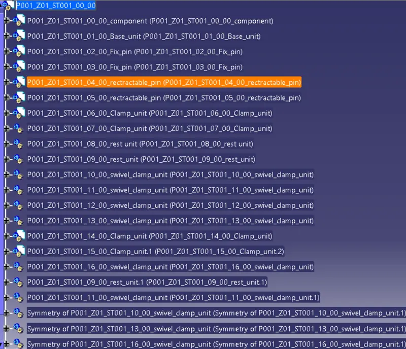
1. Renaming and structuring of the design tree :
Renaming of the design tree is done and structuring design tree in a way that its simple to identify the units. Some units are used multiple times which are identified by its name.
2. 3D FINISHING OF BASE UNIT :
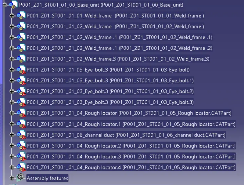
- Renaming of parts and structuring design tree.
- Colour coding given to the holes on the base plate :
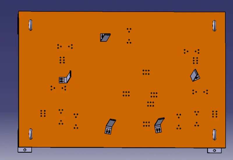
- Threaded hole and dowel holes making nominal and color coding are done so easy to distinguish holes.
- Threaded hole (yellow), clearance hole (sky blue), dowel hole (Blue), Machining surface(orange).
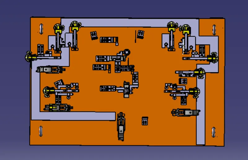
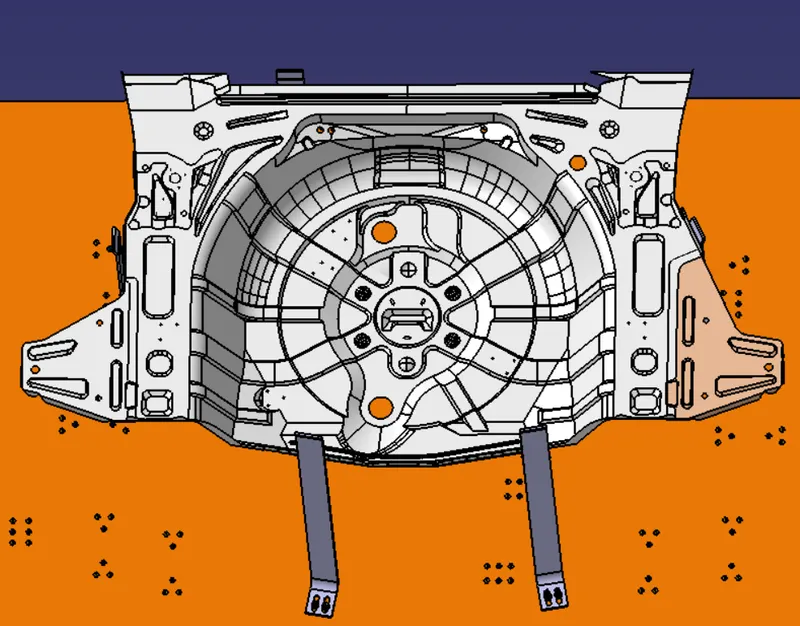
- Positioning of rough locators on the base plate :
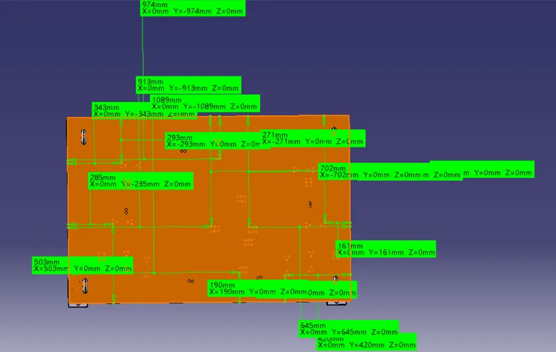
- Holes made nominal to the base plate :
- Pneumatic routing :
Checking parameters Action
Rename of the design tree Done
Mark machining area Done
Nominality Done
Holes colouring standard Done
Positioning of Rough locators Done
Pneumatic routing Done
3. 3D Finishing of rest unit :
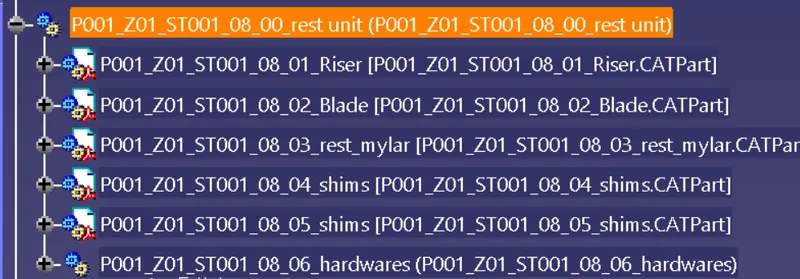
- Proper renaming of parts in the design tree:
- Colouring holes as per standards :
- Fasteners implementation :
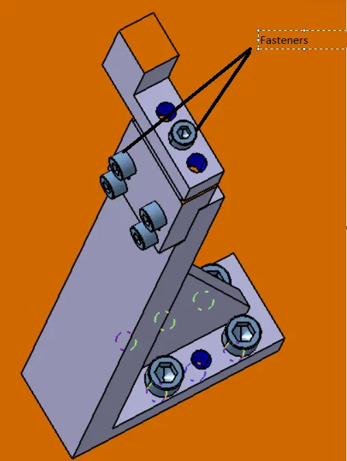
- Indicate machining area :
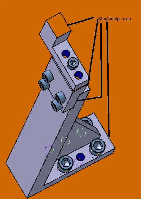
Checking parameters Action
Rename of the design Done
Indicate machining area Done
Nominality Done
Holes colouring standard Done
Fasteners implementation Done
4. 3D Finishing of clamp unit :
- Proper renaming of parts in design tree:
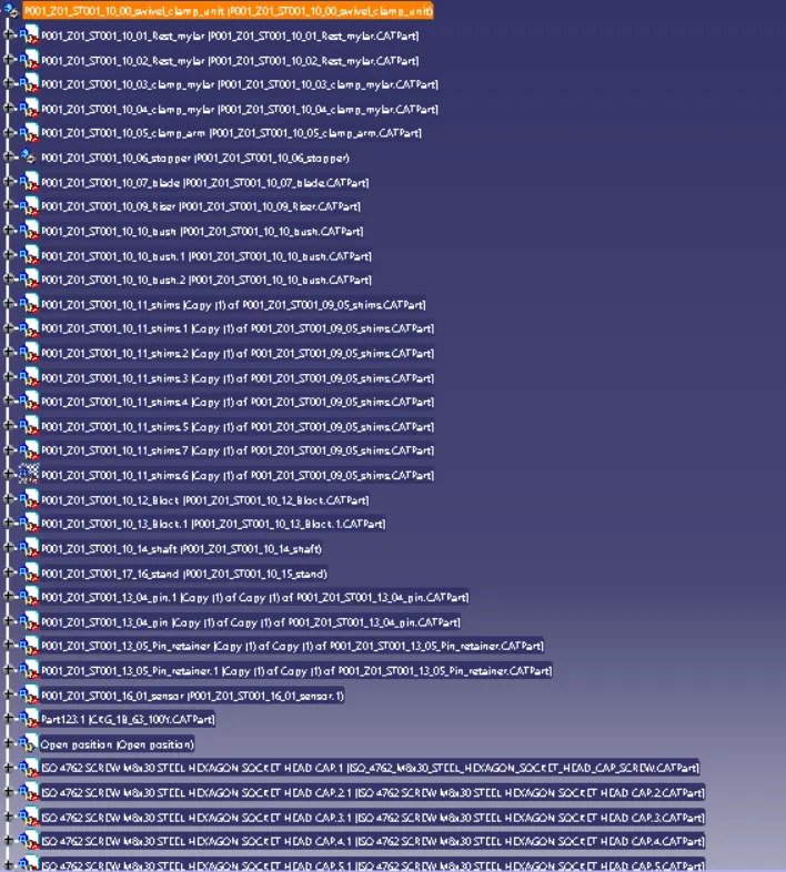
- Colouring standards for holes:
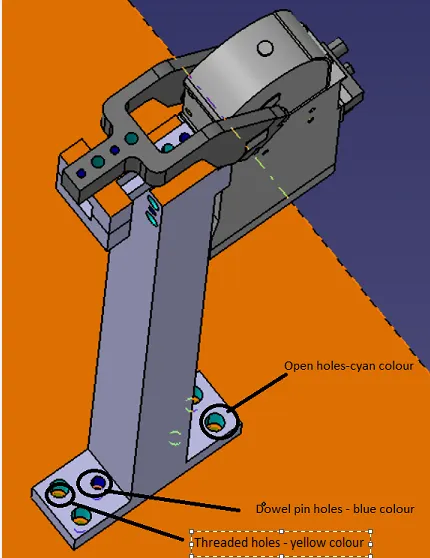
- Fasteners implementation :
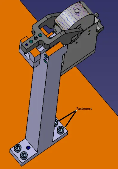
- Indicating machining area :
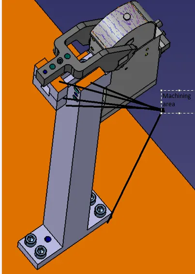
- Mylar splitting as per the panel profile :
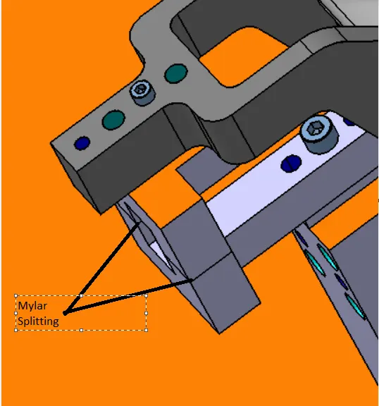
- Checking the nominality of all the units :
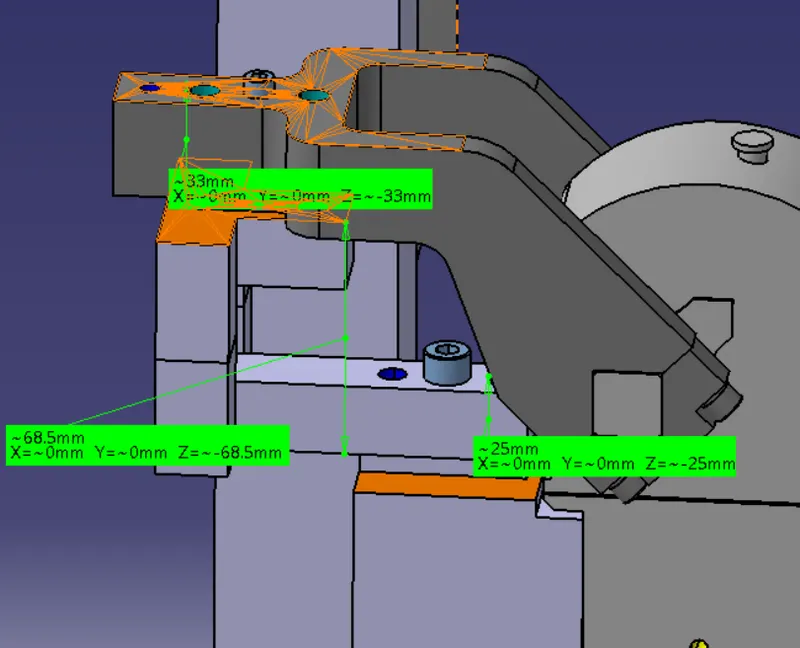
Checking parameters Action
Rename of the design tree Done
Indicate machining area Done
Nominality Done
Holes colouring standard Done
Fasteners implementation Done
Hole concentricity Done
Mylar splitting as per panel profile Done
It follows with the same procedure for both Power clamp, Swivel clamp & pin clamp units.
5. 3D finishing of pin unit :
- Proper renaming of parts in the design tree :
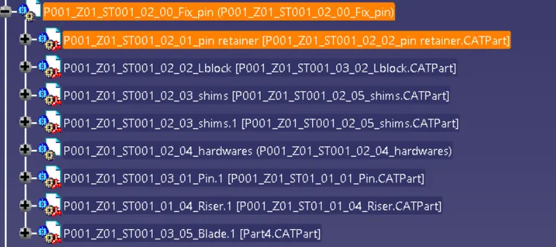
- Colouring holes as per standards :
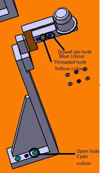
- Fasteners implementation :
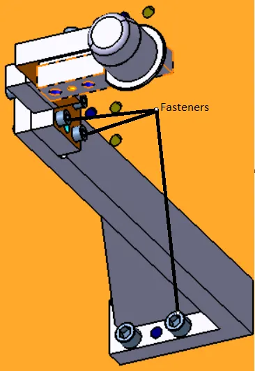
- Indicating machining area :
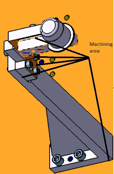
Checking parameters Action
Rename of the design tree Done
Indicate machining area Done
Nominality Done
Holes colouring standard Done
Fasteners implementation Done
Hole concentricity Done
Positioning of the units on the base plate :
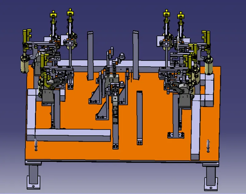
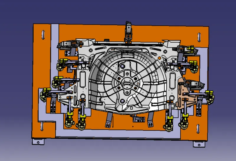
Final image of the fixture :
Conclusion :
Hence, 3D finishing is performed on the designed assembly of fixtures and rough locators were designed for the given panel.