Week 8:- 3D Finishing Challenge 2
OBJECTIVE
To Design the rough locators for the Fixture, and perform 3D finish for all the Units (including Pin Units).
Abstract
I have designed different types of pin units and clamp units and power clamp units and Rest Units for fixing the given fixture assembly. By using the 3-2-1 principle. for pin and Clamp units need to perform the 3D Finish and design the Rough Locators for the panel
Software
Catia V5
Operations to be done on 3D Finish
- Hole concentricity & Hole sizes
- Machining area the surface
- Nomilnality of the holes
- Hole coloring standard
- Gaps Checking
- Fasteners Implementation
- Pneumatic Layout
- Avoiding clash between different parts
- Mylars splitting as per panel profile
- Proper renaming of parts/assemblies as per standard
Hole concentricity & Hole sizes
All the holes in the paneL and connecting to pin units and clamp units are to be in the same concentricity and need to check the sizes of the holes.

Fig hole concentricity
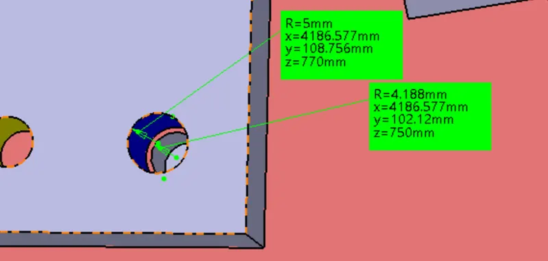
fig Hole sizes for threaded and Dowel
Machining area the surface
which are to be machined should be represented with proper finishing and to represent the machining surface that should be indicated any color.
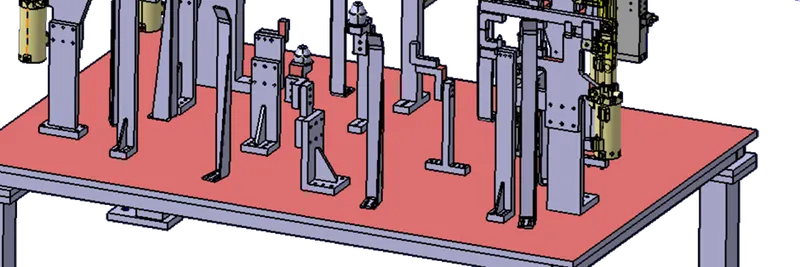
Fig Some parts face are colored for the identifications for machining
Hole coloring standard
The fasteners and dowel holes should be some standard colors.Clearance holes are aqua_blue color and threaded holes Yellow color and Dovel Navy_blue color
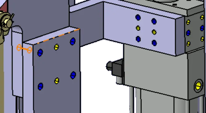
Fig dowel holes are colored blue and threaded holes are colored yellow
Gaps Checking
The gap between different units and assemblies and weld areas and other small parts need to be checked for proper assembly
Every part in the assembly was properly aligned to each other to avoid the gaps
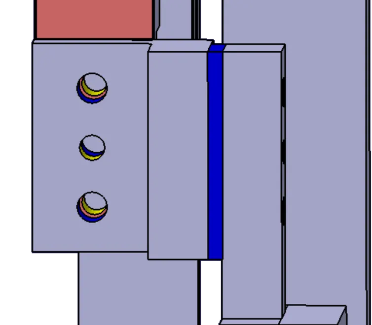
Avoiding clash between different parts
every unit and part has some gaps from panel to mylar or a pin and for checking the Weld gun clearances for welding.
Mylars splitting as per panel profile
if any mylar was located in an embossing or any curved or profile surface then the mylar must have the panel profile.
Proper renaming of parts/assemblies as per standard:
Proper renaming of parts and assembly should be done while finishing the design so that every person can understand the design.
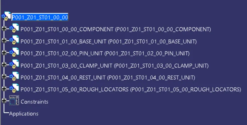
Fig Full FixtureDesign tree structure
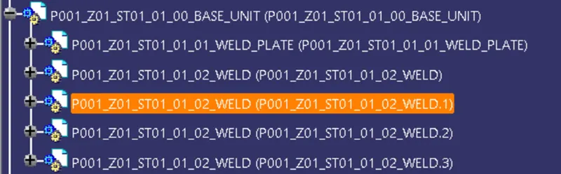
Fig Base Unit Design tree structure
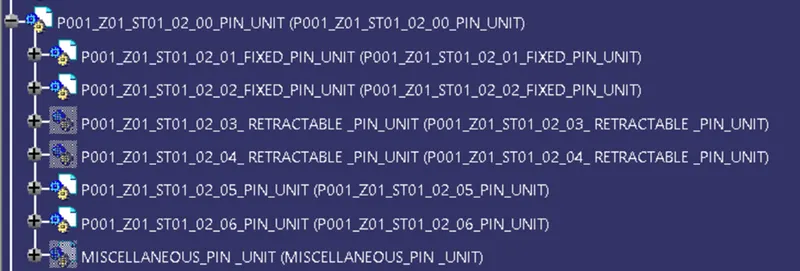
Fig pin Unit Design tree structure
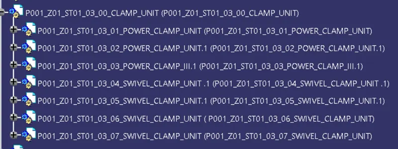
Fig Clamp Unit Design tree structure

Fig Rest Unit Design tree structure
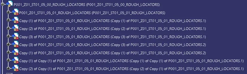
Fig Rough Locatores tree structure
Design methodology of Rough Locators
Rough Locator
Rough locators are used and designed to guide the operator to locate the panel in the exact location before entering the pin .it can be a standard part of a self-designed part
There are some points to be considered while designing the rough locators
- A rough locator should be placed at the edges of the panel which has to guide the panel.
- A rough locator has to be placed at the same angle of the car parts edge with minimum 2-5mm from the edge of the panel.
- A rough locator should arrest the direction of the panel. and the guiding should start 10-15mm before the pin engagement
- Rough locater should be designed with entry angle for panel and rough locator should have two slots to mount and for easy adjustments
- The height of the locator should not be more than the permissible ergo height of the fixture
- The entry point of the locator should be 10mm to 15 mm above the panel surface and the angle ranges from 30 -45 degrees
- A rough locator cab is a rod-type or flat type. depends upon the standard based on the requirement
By considering the panel height my rough locator height is 550mm with 6mm thickness and the base of 70mm with 6mm thick. and the head inclined at an angle of 170degrees with 50mm length.
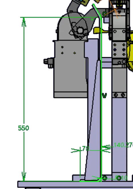
Fig rough locator sketch
To give some strength to the rough locator added a stiffener to the rough locator
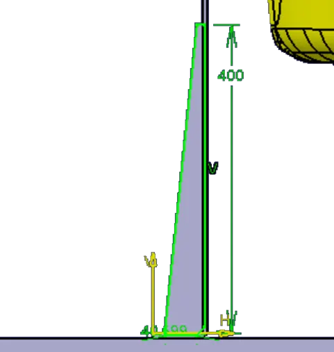
Fig stiffener sketch
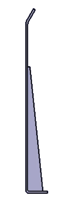
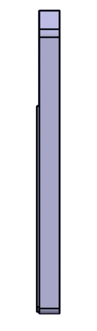
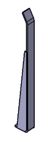
Fig Rough Locator Views
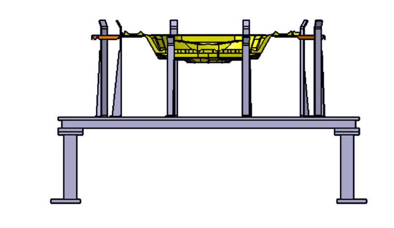
Fig Rough Locators with panel (front View)
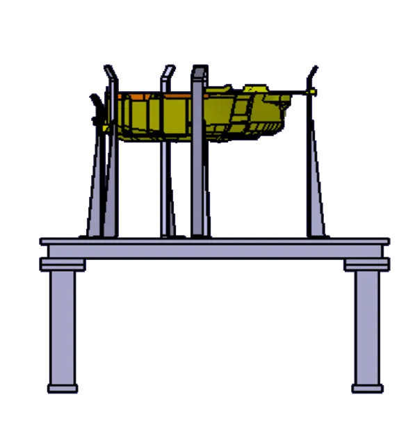
Fig Rough Locators with panel (side view)
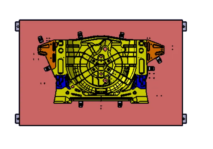
Fig Rough Locators with panel (Top View)
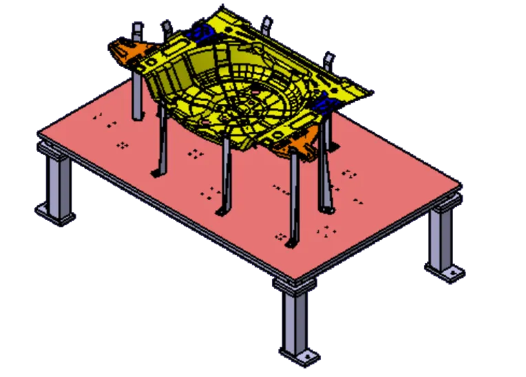
Fig Rough Locators with panel (ISO View)
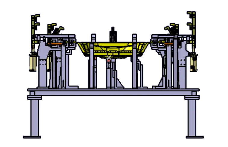
Fig FINAL FIXTURE ASSEMBLY with panel (Front View)
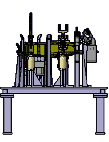
Fig FINAL FIXTURE ASSEMBLY with panel (Side View)
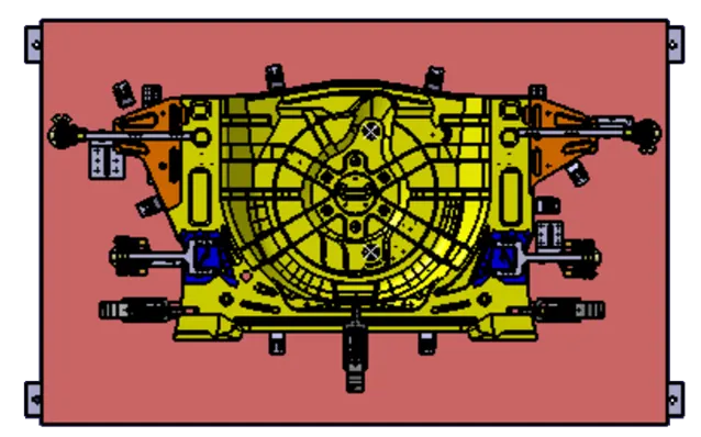
Fig FINAL FIXTURE ASSEMBLY with panel (Top View)
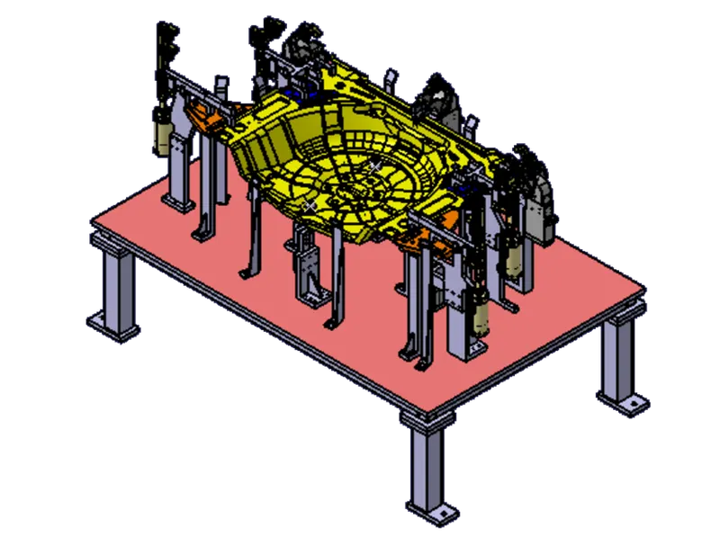
Fig FINAL FIXTURE ASSEMBLY with panel (Iso View)
Conclusion
Hence as per the design was named as (P001_Z01_ST01_00_00) and the base unit names as (P001_Z01_ST01_01_00_BASE_UNIT), PIN_UNIT(P001_Z01_ST01_02_00_PIN_UNIT) , CLAMP_UNIT(P001_Z01_ST01_03_00_CLAMP_UNIT) AND REST_UNIT(P001_Z01_ST01_04_00_REST_UNIT), And Rough Locators(P001_Z01_ST01_05_00_ROUGH_LOCATORS) designed using CatiaV5 Successfully for 3D finishing.