Week 8:- 3D Finishing Challenge 2
AIM:
To perform 3D finish to all the units and to create rough locators for the assembly fixture design of the given panel.
Abstract:
In this project the rough locators are designed for the assembly of fixture and 3D finishing is done for all the units of the assembly.
Introduction:
3D Finish:
- It is the process where the design is being completely finished and further moved to the simulation and 2D detailing.
- To ease the assembly of all the units, nominality of the designed parts are checked. The hole concentricity and the hole sizes are also checked which ensures the assembly of the various parts.
- The gaps between the different units are also checked to ensure the proper working of individual units. The rough locators are to be designed for guiding the proper orientation of the panel onto the fixture.
- Gun study is the major and the most important part of the 3D finishing. Design the pneumatic lay-out for pneumatic connection.
- Selection of sensors and solenoid valves as per the requirement and implementation in design.
- Fasteners are implemented as per the hole size and standard colour codes are applied as per the customer requirement to differentiate the type of the hole whether it is dowel hole or threaded hole or clearance hole.
- Renaming of the assembly and part is done to differentiate each part from the others so that everyone can identify in which assembly the part is going to be fit.
- After all these are done the model is sent for simulation and 2D detailing.
The following points are needed to be taken care while finishing the design:
1. Hole concentricity and Hole sizes:
To provide ease of assembly all part hole concentricities and hole sizes are checked.
2. Machining area:
The machining area in every part should be defined and it should be highlighted by using a standard colour code. Machining is to be done on parts to properly mount with mating parts. Machinig only on desired faces reduces cost and saves time. And also machining increases the accuracy of dimension. So before going to simulation or detailing machining area should be defined.
3. Nominality:
All unit dimensions should be maintained nominal to facilitate easy assembly of the unit.
4. Holes colouring standard:
It is done in 3D finishing to help identify the type of hole. It depends on customer standards of specific colour like,
- The dowel hole is given blue colour
- The threaded hole is given yellow colour
- Counterbore, open hole are given cyan blue colour
5. Pneumatic Lay-outing:
The pneumatic lay-outing is a collection of different pneumatic pipes which work as an inlet to the pneumatic cylinder. It should be done properly for the proper functioning of the units.
6. Gaps checking:
The gaps between the different units are checked to ensure the proper individual working of different units.
7. Fasteners implementation:
Fast should be implemented in all the units as per the requirement and load on the part.
8. Avoiding clash between different parts:
A proper gap should be maintained between units to avoid clashes between the different units.
9. Mylar splitting as per panel profile:
Mylar splitting as for panel profile should be confirmed while finishing the design.
10. Proper renaming of parts or assemblies as per the standards:
Proper renaming of parts and assembly should be done while finishing the design and hence we can identify each and every part easily with unique identification.
Fixture assembly - P001_Z01_ST010_00_00
Re-ordering and proper renaming of the design tree:
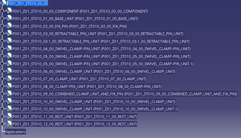
It is the first and foremost step in 3D finishing that includes the renaming of the various units and arranging in the proper order needed.
Various units of the assembly under 3D finishing:
1. Base unit: P001_Z01_ST010_01_00_BASE_UNIT
- A base unit is the unit designed to mount all the other units (Clamp unit, Pin unit, Rest unit,etc.,) of the tool.
- It also holds other parts necessary for a tool like pneumatic valve box, Trunking channel, base plate eye bolt will also be mounted on to a base unit.
- It is the fundamental component of the fixture because all the other components are mounted over it. So every fixture has base unit.
- The base unit is different according to the panel, design of clamp system, location system, etc.,
Fundamentals of Base unit:
- A base plate size should cover all the units with its outer periphery including the opening.
- A base plate is always preferred to be designed with respect to BCS Coordinates.
- A base plate should be drilled with datum holes/ measuring holes in line with a pitch of 1000 m in general.
- The number of datum holes depend on the size of the base plate.
- Datum holes should be drilled at nominal values of co-ordinates and in terms of 50 and 100. Example, X=100, Y=-600, Z=250.
- Datum holes should be covered with cover plates.
3D finishing of Base unit:
| Checking parameter | Action |
| Renaming & Structuring of design tree | Done |
| Nominality of holes | Done |
| Hole colouring standard | Done |
| Machined area defined | Done |
- Renaming and structuring of design tree:
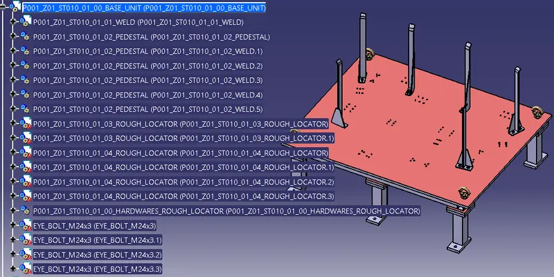
Fig(1.1): Design tree of base unit
- Nominality of holes:
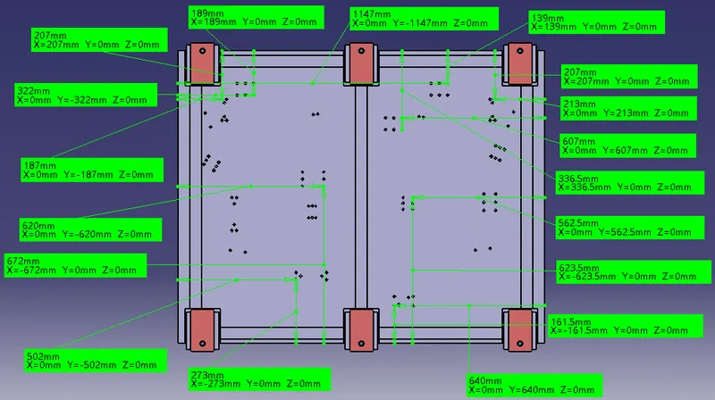
FIG(1.2): Nominality of all holes
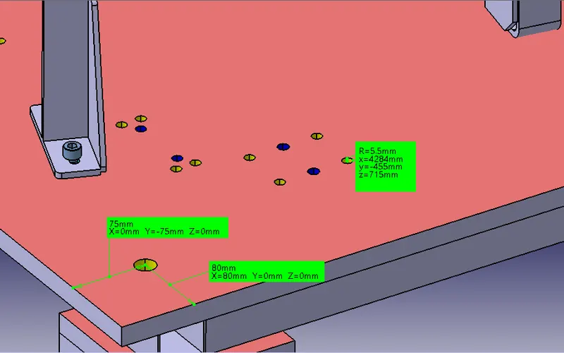
Fig(1.3): Nominality of holes
- Hole colouring Standard:
- Threaded hole - Yellow colour
- Dowel hole - Blue colour
- Open hole - Cyan Green colour
- Machined area - Cream colour
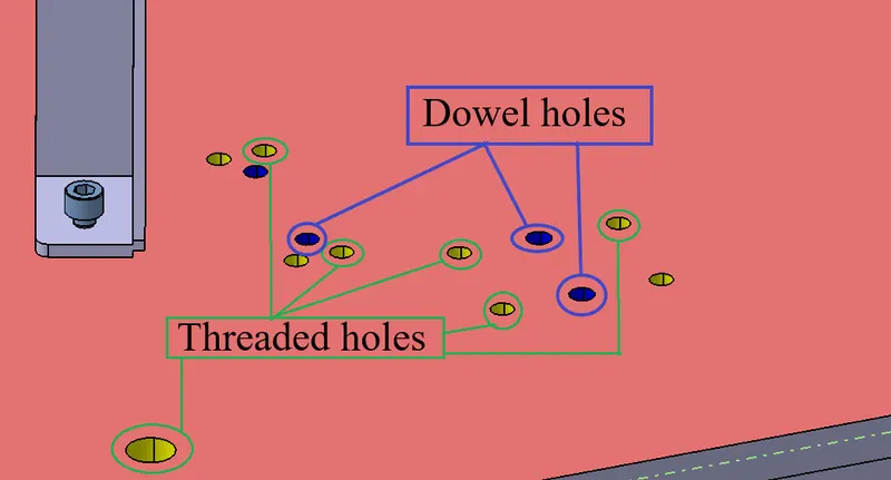
Fig(1.4): Hole colouring standard
Rough Locator Design:
- A rough locator is a part designed to guide the panel positioning, to locate the car panel onto the pins accordingly. A rough locator can be of standard part or a make part.
- Rough locators also work as Poka-yoke. Poka-yoke is a Japanese concept used for mistake-proofing.
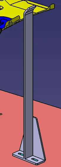
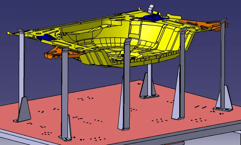
Fig(1.5): Rough locator Fig(1.6): Rough locators assembly
- They are also used to help locate the workpieces in the automation process. Locating refers to the desired location where you want the workpiece to be when it is getting worked on either by a person or a team or a robot.
- The accuracy of the locating components directly affects the consistency and how the final product will come out. This is why these components are essential to our setup.
- It can be also called fool proofing method. Because without a rough locator the part cannot be loaded in correct position.
- The rough locators are set accordingly to the angle of the respective panel and hence the part can be loaded in a defined direction and orientation only.
The following are the points needed to be taken into consideration while designing the rough locator:
- A rough locator should be placed at the edges of the car panel, which it has to guide.
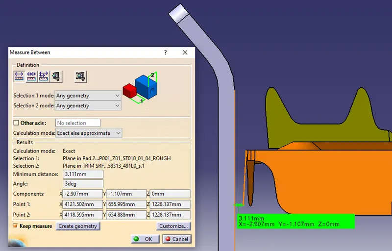
Fig(1.7)
- A locator has to be placed at the same angle of the car panel edge with a minimum distance of 2-5 mm from the edge of the car.
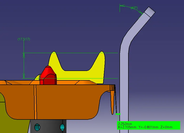
Fig(1.8)
- The rough locator should start guiding the panel before 10 to 15 mm to the start of the pin engagement.
- The applicator should be designed with an entry angle for the car panel. Generally, it ranges between 30-45 degrees.
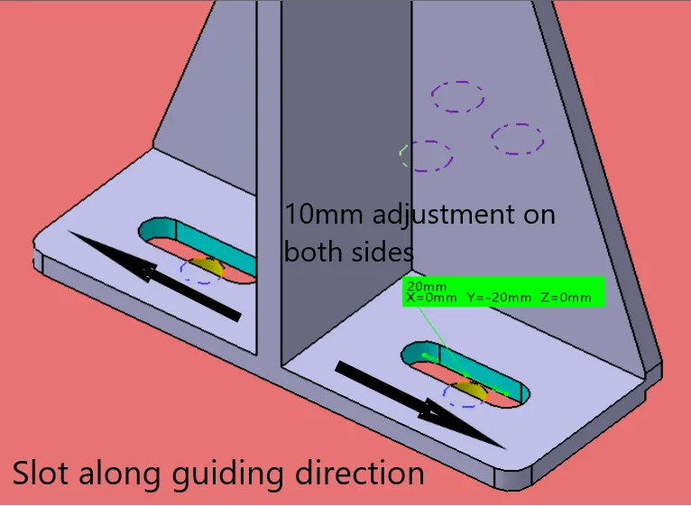
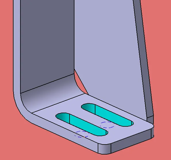
Fig(1.9) Fig(1.10)
- Rough locator should guide the panel in pin arresting.
- A rough locator should be designed with the 2 slots to mount the locator and easy adjustment.
- The slot should be in the direction of the car part guiding.
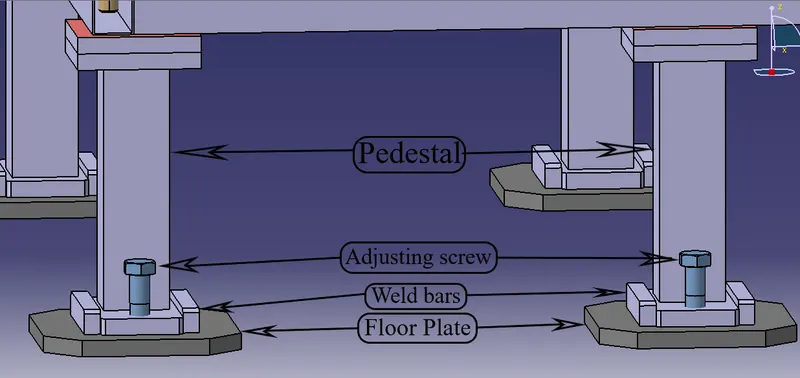
Fig(1.11): Pedestal modification
CLAMP UNITS:
- A clamp unit is a unit designed to clamp/hold the car panel with NC blocks/Mylars/Rest by using a pneumatic clamping cylinder.
- Some of the parts of the clamp unit is clamp arm, finger, rest/backup, L-block, shims, Risers and Pneumatic cylinders.
- Types of clamp units:
-Swivel cylinder clamp unit
-Power clamp unit
Fundamentals of clamp unit design:
- It is preferred to design clamp unit with pivot centerline in-line with clamp surface. When possible upto 25mm offset can be acceptable.
- For sigle angular clamping, it is recommended that the centerline of clamp pivot be positioned on plane that is created by surface being clamped, upto 15 degree off normal pivot location can be used in extreme cases where recommended clamping condition cannot be satisfied.
- There should be adequate space between the cylinder & the riser to allow the swinging motion of the cylinder while opening & closing.
- Clamp-pin unit is used where it is necessary to locate 2 panels for operations like welding.
- All parts should snap & butt properly to each other.
- Maintain a distance of 10mm to 12mm between the panel and other clamp parts.
- Avoid any clash to prevent issues at assembly.
PURPOSE OF CLAMP UNIT:
- The purpose of clamping tools is to securely hold the workpiece in position without obstructing the production process.
- It prevents the distortion during welding process and other processes.
- High clamping forces combined with compact dimensions are therfore the most important requirements for a clamping tool. For this reason, clamps are also equipped with mechanical transmission gear units.
2. A.Swivel clamp unit: P001_Z01_ST010_10_00_SWIVEL_CLAMP_UNIT ; P001_Z01_ST010_06_00_SWIVEL_CLAMP_UNIT
- Swivel clamp unit is designed to clamp/hold the car panel with clamp/rest mylar by using a pneumatic clamp cylinder.
- Clamp mylar is connected to pivoted clamp arm which is connected to the pneumatic cylinders. Down stroke of the cylinder opens the clamp.
- Usually clamp open posotion is 90 degree.
- Swivel clamp consists of clamp/rest mylars, blade, clamp arm, stopper, pivot plate, riser and shims.
3D finishing of Swivel clamp unit:
| Checking parameter | Action |
| Renaming and structuring the design tree | Done |
| Nominality of holes | Done |
| Concentricity of holes | Checked |
| Hole colouring standard | Done |
| Mylar splitting as per panel profile | Done |
| Butting of each parts | Done |
| Machined area | Defined |
- Renaming and structuring of design tree:
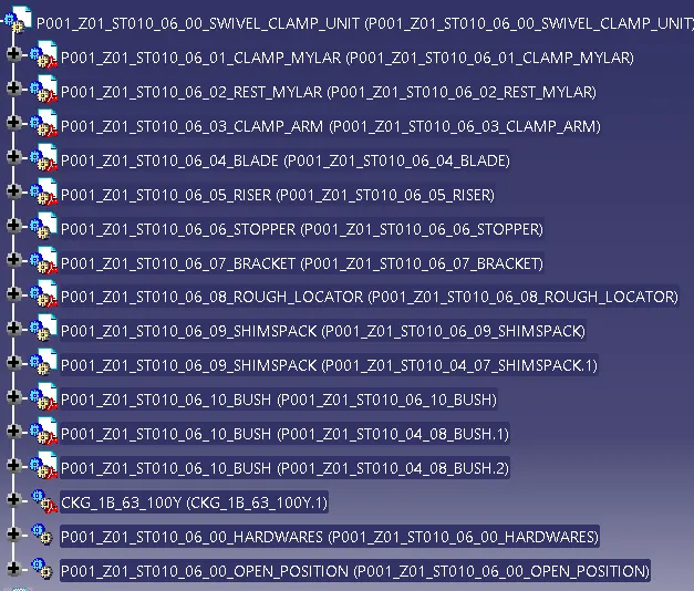
Fig(2.1): P001_Z01_ST010_06_00_SWIVEL_CLAMP_UNIT
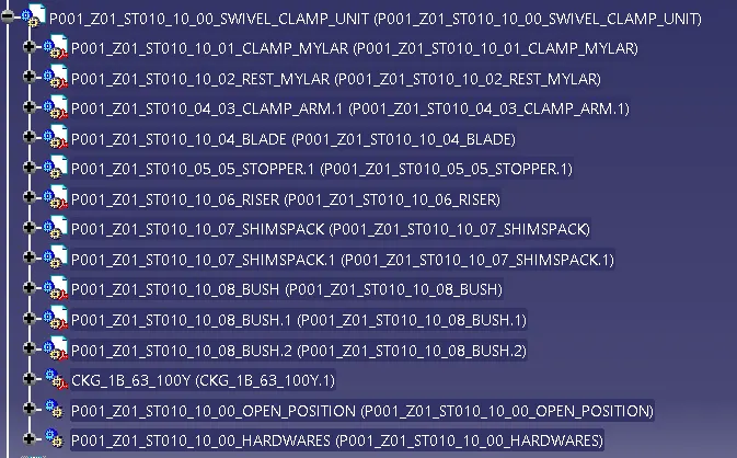
Fig(2.2): P001_Z01_ST010_10_00_SWIVEL_CLAMP_UNIT
- Nominality of holes:
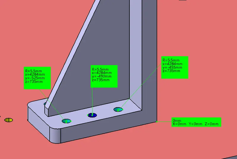
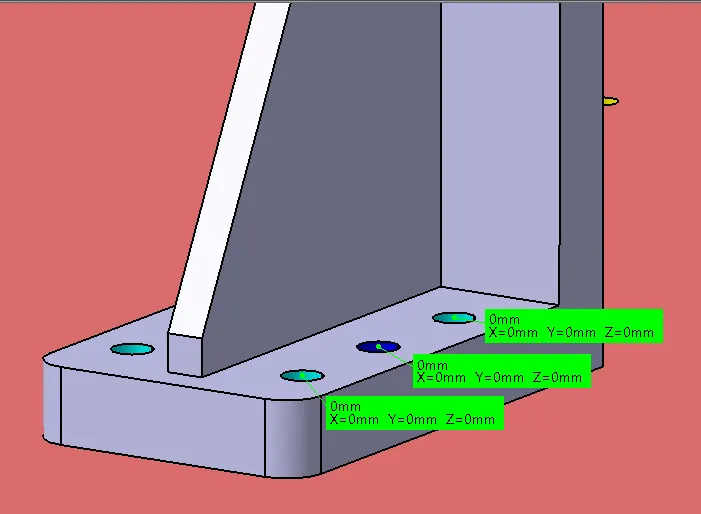
Fig(2.3): All hole co-ordinates are made nominal
- Hole concentricity & Colouring standard:
Each hole is made concentric with respective hole of the mating parts.
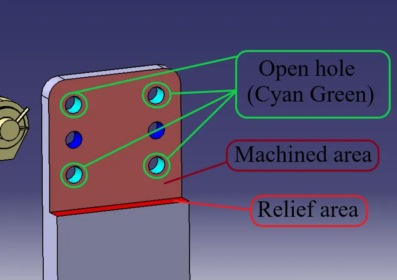
Hole colouring standards:
- Threaded hole - Yellow colour
- Dowel hole - Blue colour
- Open hole - Cyan Green colour
- Machined area - Cream colour
- Relief area - Red colour
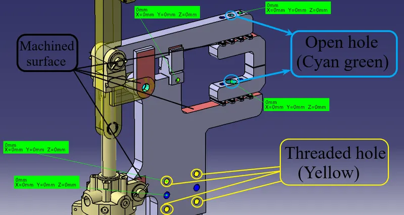
Fig(2.4): Hole colouring standard and hole concentricity
Fig(2.5) Fig(2.6)
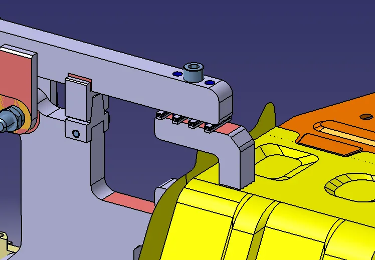
- Mylar splitting as per panel profile:
Fig(2.7)
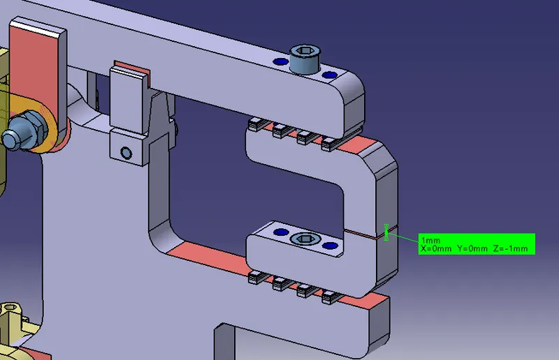
Fig(2.8): Splitting of mylars as per panel profile
- Butting of each parts:
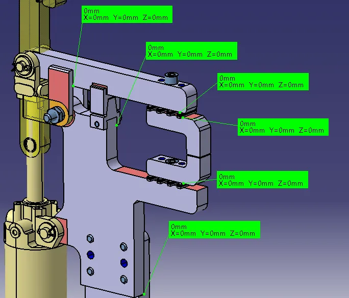
Fig(2.9): Butting of each matting part is done
B. Swivel clamp-Pin unit:
(P001_Z01_ST010_04_00_SWIVEL_CLAMP-PIN_UNIT ; P001_Z01_ST010_05_00_SWIVEL_CLAMP-PIN_UNIT)
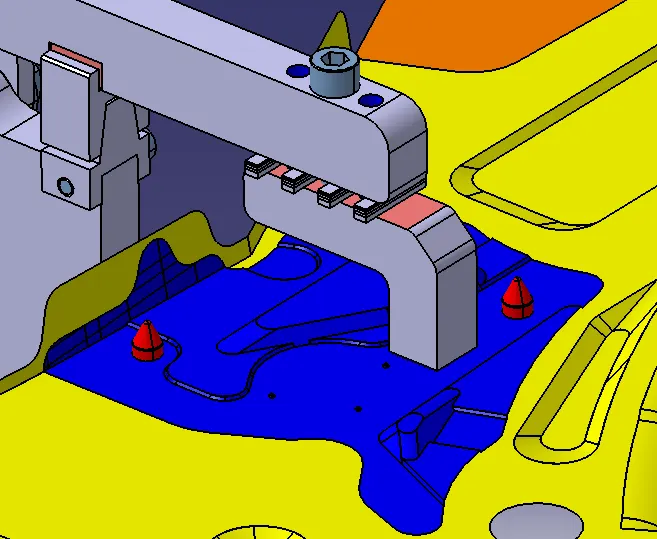
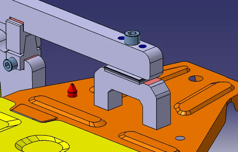
Fig shows: Pin position
Clamp-Pin unit:
- Pin unit is a unit designed to locate car panels using pins.
- It consists of riser, blade, block, pin retainer, pin, shims or spacers and cylinders(incase of retractable pin unit).
- Pin unit is a part of the 3-2-1 locating principle of fixture design.
- It restricts 6 degrees of freedom of the part.
- This is sometimes provided with the clamp unit when two panels are to be located for any operations like welding.
Fundamentals to be considered for pin design:
- Pin should engage at 3 to 5 mm from car panel entry surface.
- All pins should be accommodated with 2-way adjustable shims irrespective of direction of arresting.
- Round pins should be used incase of 4way arresting of car part if the hole is round.
- Round pins can be used for 2 way arresting of car parts only if the hole is slotted.
- Diamond pins should be used for 2 way arrresting of car part if the hole is round.
- Diamond pins should be used incase of 4 way arresting of car parts if the hole is slotted.
3D finishing of Swivel clamp-pin unit:
| Checking parameter | Action |
| Renaming and structuring the design tree | Done |
| Nominality of holes | Done |
| Concentricity of holes | Checked |
| Hole colouring standard | Done |
| Mylar splitting as per panel profile | Done |
| Butting of each parts | Done |
| Machined area | Defined |
- Renaming and structuring of the design tree:
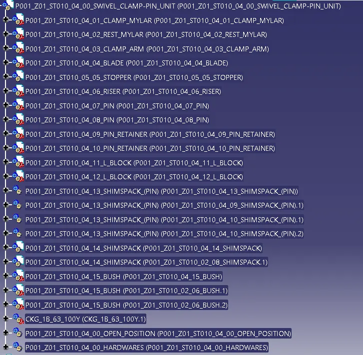
Fig(2.10): P001_Z01_ST010_04_00_SWIVEL_CLAMP-PIN_UNIT
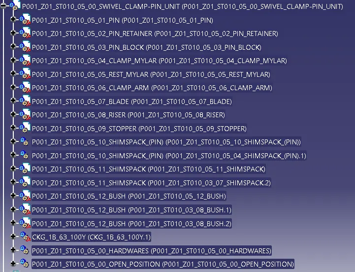
Fig(2.11): P001_Z01_ST010_05_00_SWIVEL_CLAMP-PIN_UNIT
- Nominality of holes:
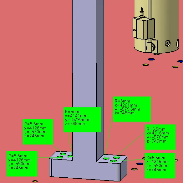
Fig(2.12): All holes are made nominal
- Hole concentricity & Colouring standard:
Each hole is made concentric with respective hole of the mating parts.
Hole colouring standards:
- Threaded hole - Yellow colour
- Dowel hole - Blue colour
- Open hole - Cyan Green colour
- Machined area - Cream colour
- Relief area - Red colour
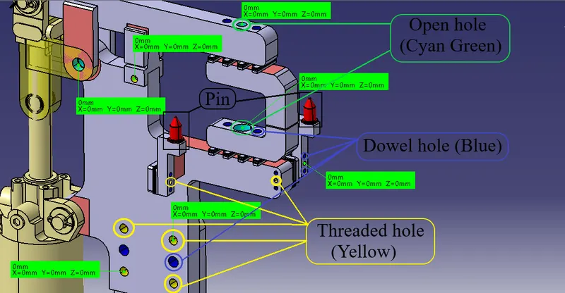
Fig(2.13): All holes are made concentric with respective holes and coloured as per standard
- Butting parts:
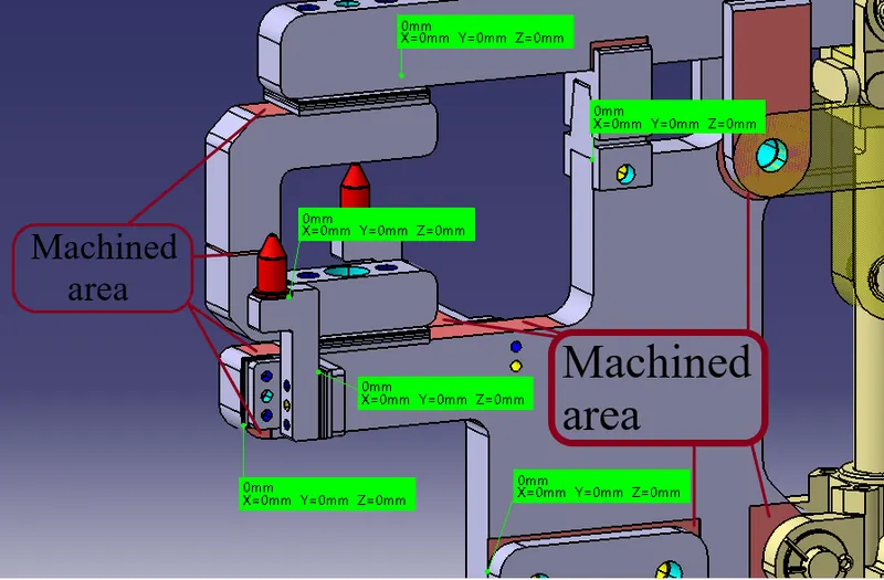
Fig(2.14): Mating parts are machined properly
- Splitting of mylars:
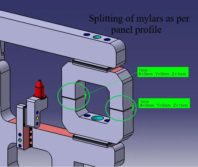
Fig(2.15): Splitting of mylars
- Machined area:
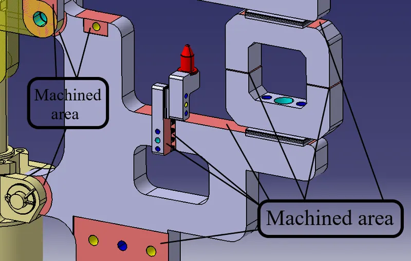
Fig(2.16): Machined areas are defined
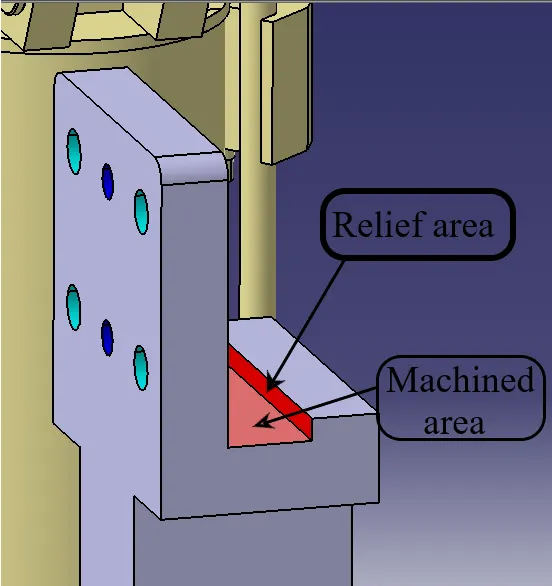
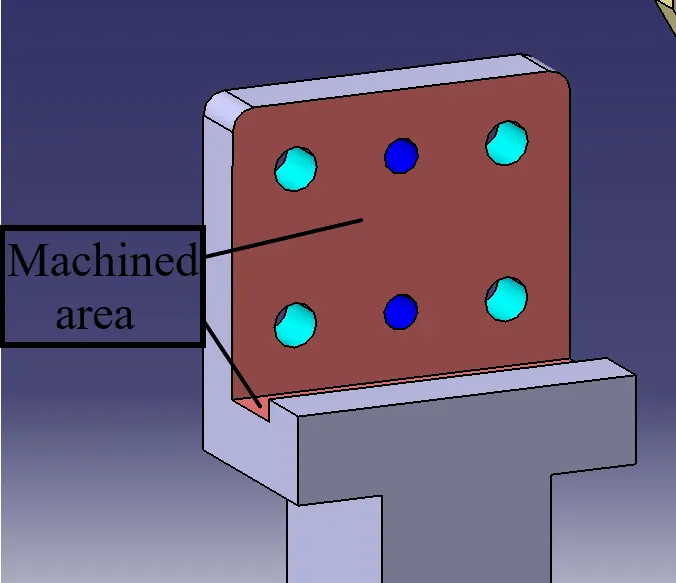
Fig(2.17) Fig(2.18)
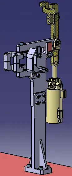
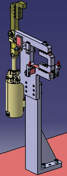
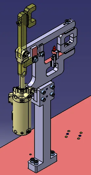 P001_Z01_ST010_06_00_SWIVEL_CLAMP_UNIT P001_Z01_ST010_04_00_SWIVEL_CLAMP-PIN_UNIT P001_Z01_ST010_05_00_SWIVEL_CLAMP-PIN_UNIT
3. A. Power Clamp unit: P001_Z01_ST010_07_00_CLAMP_UNIT
In this type of clamp unit power cylinders are used to hold the panel in its position.
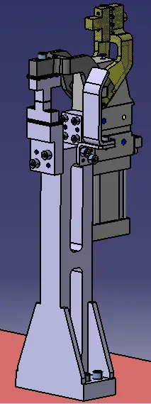
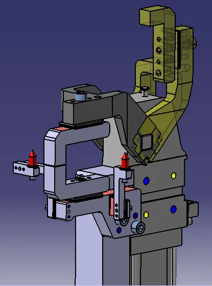
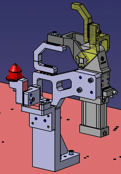
P001_Z01_ST010_07_00_CLAMP_UNIT P001_Z01_ST010_08_00_CLAMP-PIN_UNIT P001_Z01_ST010_09_00_CLAMP-PIN_UNIT
3D finishing of Power clamp unit:
| Checking parameter | Action |
| Renaming and structuring the design tree | Done |
| Nominality of holes | Done |
| Concentricity of holes | Checked |
| Hole colouring standard | Done |
| Mylar splitting as per panel profile | Done |
| Butting of each parts | Done |
| Machined area | Defined |
- Renaming and structuring of the design tree:
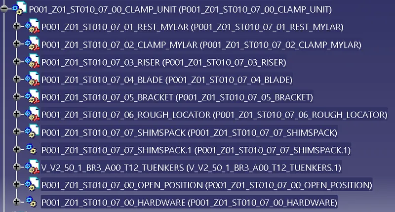
Fig(3.1)
- Nominality of holes:
The base holes are adjusted so that the co-ordinates of the holes are nominal.
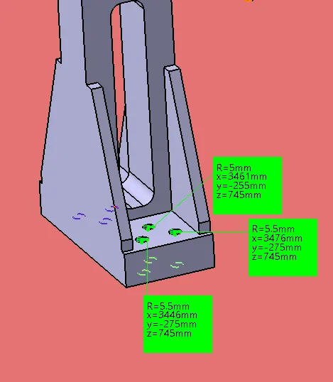
Fig(3.2)
- Hole concentricity & Standard colouring:
Each hole is made concentric with respective hole of the mating parts.
Hole colouring standards:
- Threaded hole - Yellow colour
- Dowel hole - Blue colour
- Open hole - Cyan Green colour
- Machined area - Cream colour
- Relief area - Red colour
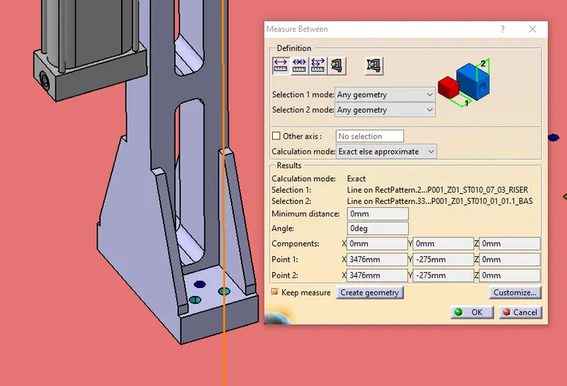
Fig(3.3): Hole concentricity
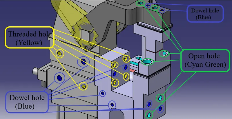
Fig(3.4): Hole colouring standards
- Mylar splitting:
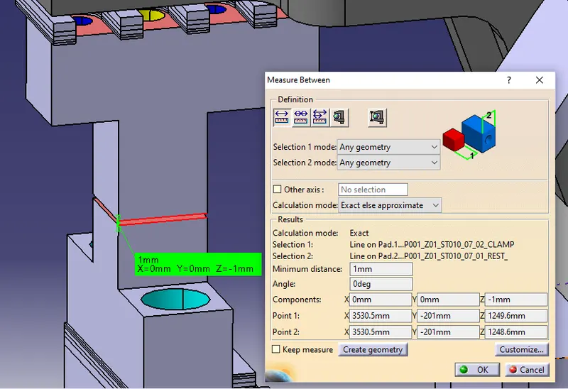
Fig(3.5): Mylar splitting is done as per the panel profile
- Butting parts:
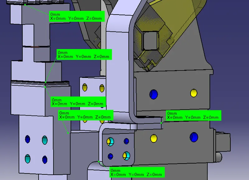
Fig(3.6): Butting of mating parts
- Machined area defined:
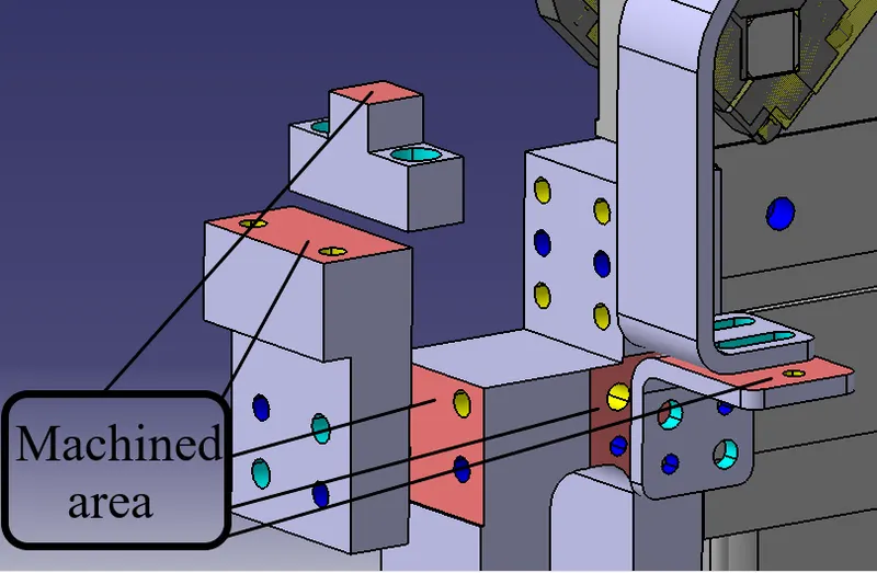
Fig(3.7): All butting surfaces are machined
B. Power clamp- Pin unit:
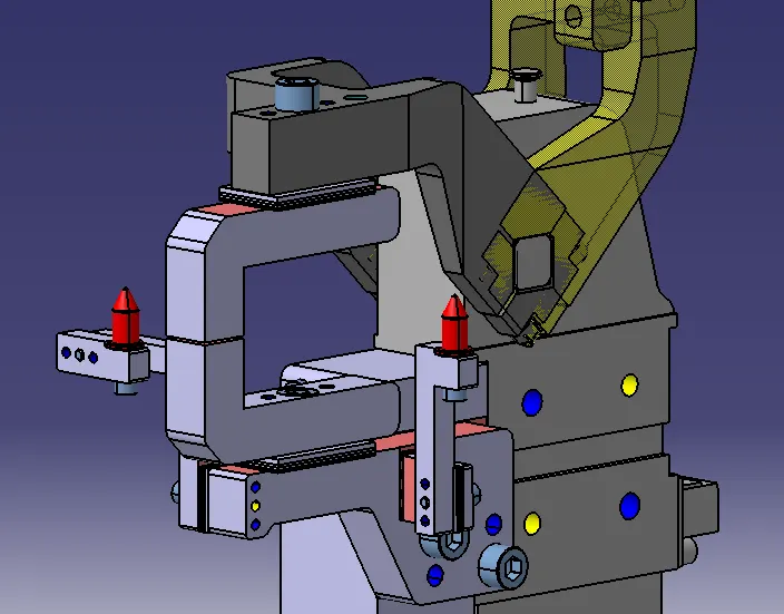
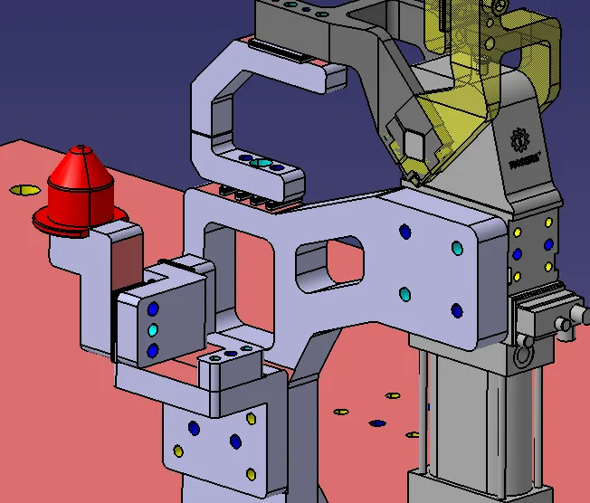
Fig shows: Power clamp units with Pin
Clamp-Pin unit:
- Pin unit is a unit designed to locate car panels using pins.
- It consists of riser, blade, block, pin retainer, pin, shims or spacers and cylinders(incase of retractable pin unit).
- Pin unit is a part of the 3-2-1 locating principle of fixture design.
- It restricts 6 degrees of freedom of the part.
- This is sometimes provided with the clamp unit when two panels are to be located for any operations like welding.
Fundamentals to be considered for pin design:
- Pin should engage at 3 to 5 mm from car panel entry surface.
- All pins should be accommodated with 2-way adjustable shims irrespective of direction of arresting.
- Round pins should be used incase of 4way arresting of car part if the hole is round.
- Round pins can be used for 2 way arresting of car parts only if the hole is slotted.
- Diamond pins should be used for 2 way arrresting of car part if the hole is round.
- Diamond pins should be used incase of 4 way arresting of car parts if the hole is slotted.
3D finishing of Power clamp-pin unit:
| Checking parameter | Action |
| Renaming and structuring the design tree | Done |
| Nominality of holes | Done |
| Concentricity of holes | Checked |
| Hole colouring standard | Done |
| Mylar splitting as per panel profile | Done |
| Butting of each parts | Done |
| Machined area | Defined |
- Renaming and structuring the design tree:
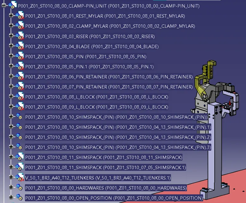
Fig(3.8)
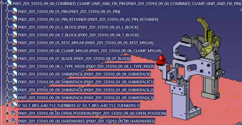
Fig(3.9)
- Nominality of holes:
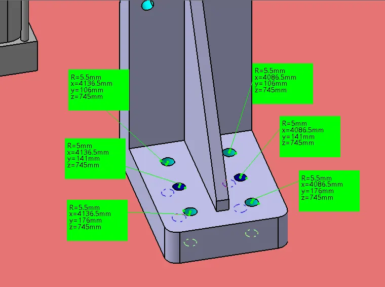
Fig(3.10): Nominality of holes
- Hole concentricity & colouring standard:
Each hole is made concentric with respective hole of the mating parts.
Hole colouring standards:
- Threaded hole - Yellow colour
- Dowel hole - Blue colour
- Open hole - Cyan Green colour
- Machined area - Cream colour
- Relief area - Red colour
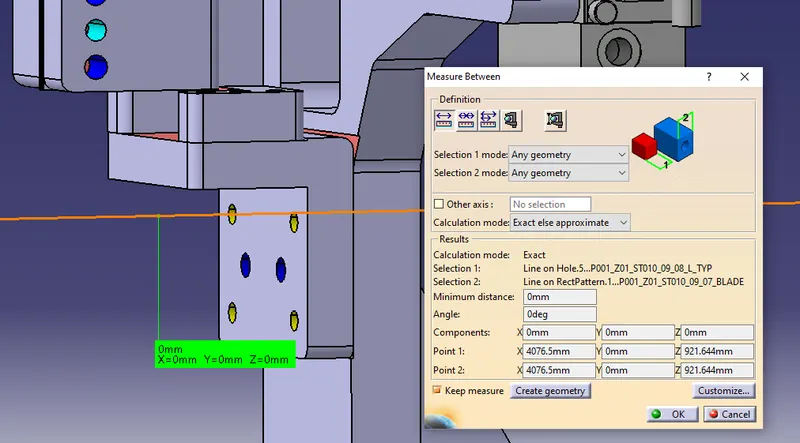
Fig(3.11): Hole concentricity
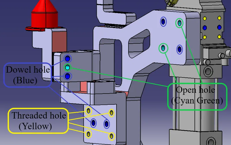
Fig(3.12): Hole colouring standard
- Mylar splitting as per panel profile:
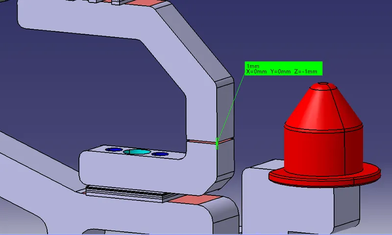
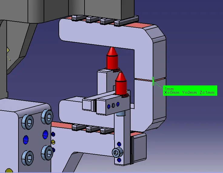
Fig(3.13) Fig(3.14)
- Butting parts:
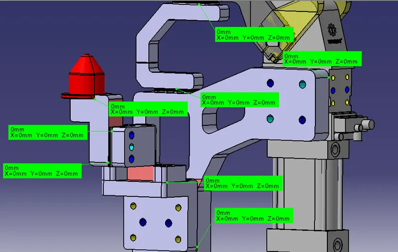
Fig(3.15): Butting of matting parts
- Machined area:
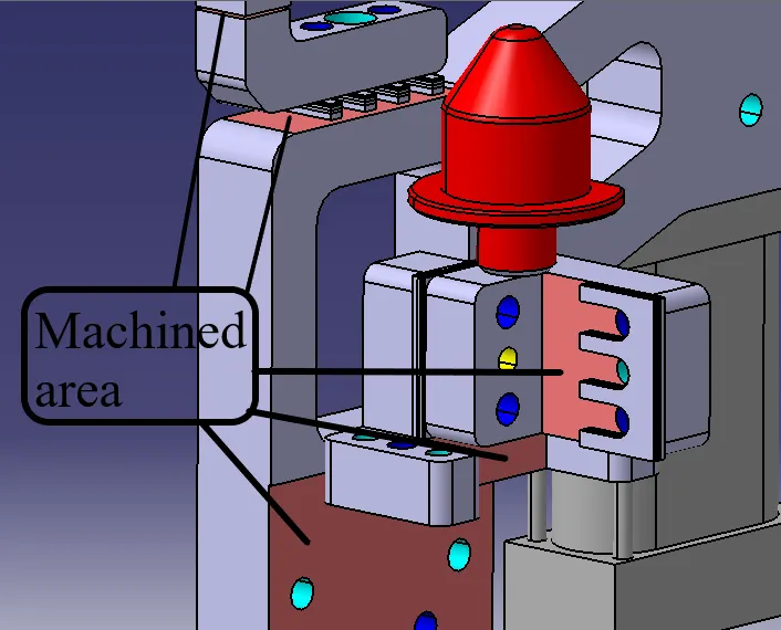
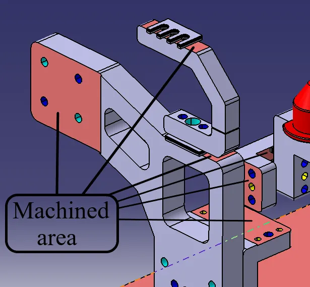
Fig(3.16) Fig(3.17)
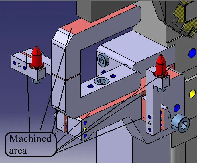
Fig(3.18)
- Fasteners implementation:
Fasteners are implemented as per the required size of the hole and checked for concentricity with the holes.
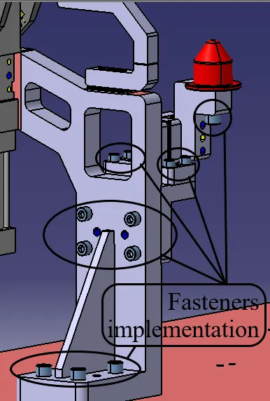
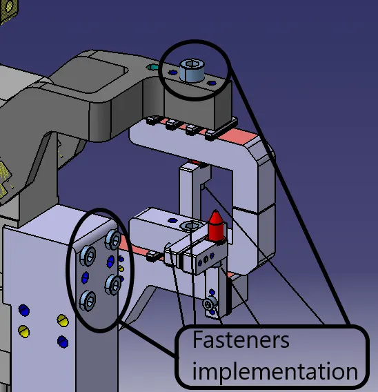
Fig(3.19) Fig(3.20)
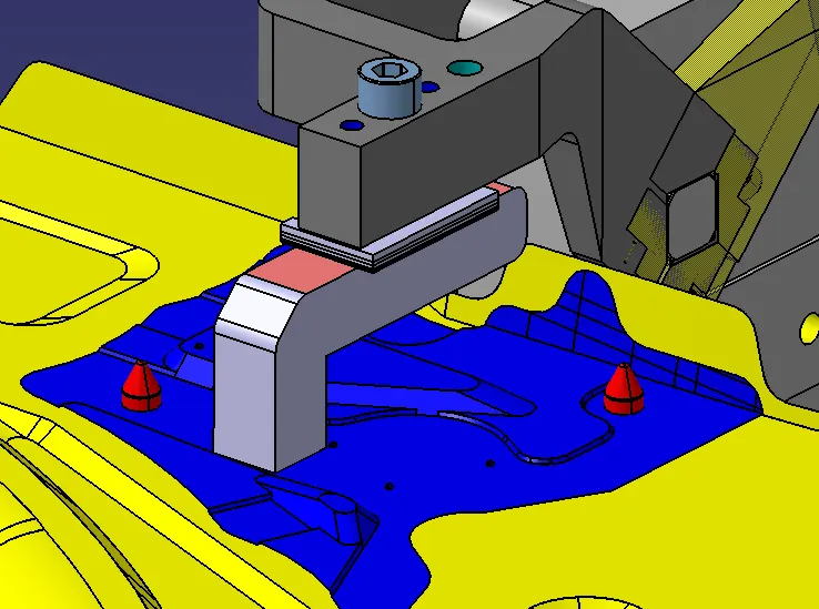
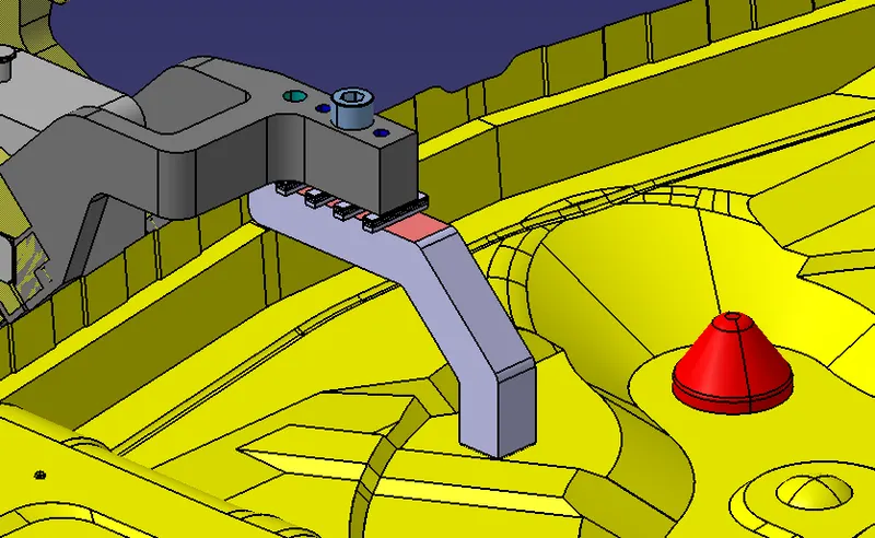
Fig(3.21): Pin positions Fig(3.22): Pin position
Material used:
In general, the materials used for Mylars, Clamp arm, shims, block, blades & risers are:
- Mylars: UHMW, Nylon66, PP, Teflon (polytetrafluroethylene (PTFE). Materials of clamp block and rest block to be decided as per the A class panel or B class.
- Clamp arm: SAE 4140 or SAE 1045.
- Shims / Spacer: S.A.E. 1010 CRS FULL HARD, COLD ROLLED STRIP STEEL S.A.E. 1010 FULL HARD, S.A.E. 1020 HRS, etc.,
- Block: STEEL ASTM A-36, NM STAINLESS, STEEL ASTM A-36, SS type 303 or 304,etc.,
- Blade: STEEL ASTM A-36,etc.,
- Riser: STEEL ASTM A-36,etc.,
HARDNESS:
In general, the hardness of the materials for pins, pin retainers, shims, shim block, blades and risers are 55-60 HRC to a depth of 0.5-0.7 mm after grinding.
SURFACE FINISH:
In general, the surface finishes of the materials for pin, pin retainer, shims, shim block, blades and risers are:
- Clamp arm: Munsell No.3.75YR6/14 safety orange.
- Shims/spacers: BLACK OXIDE FINISH (SURFACES TO BE FLAT AND PARALLEL TO WITHIN 0.012 mm T.I.R.)
- Riser: SURFACES TO BE FLAT, PARALLEL & PERPENDICULAR TO WITHIN 0.015 T.I.R.
4. Pin Units: P001_Z01_ST010_02_00_FIX_PIN ; P001_Z01_ST010_03_00_RETRACTABLE_PIN_UNIT
- Pin unit is a unit designed to locate car panels using pins.
- It consists of riser, blade, block, pin retainer, pin, shims or spacers and cylinders(incase of retractable pin unit).
- Pin unit is a part of the 3-2-1 locating principle of fixture design.
- It restricts 6 degrees of freedom of the part.
Fundamentals of pin unit design:
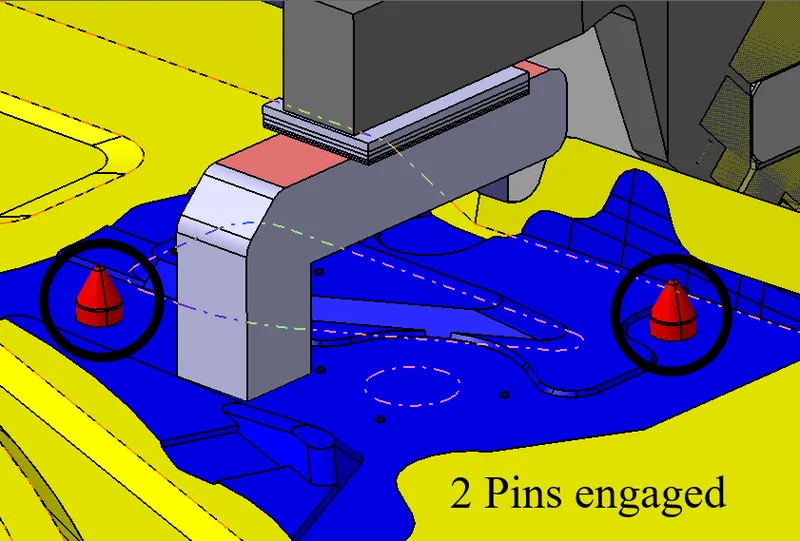
Fig(4.1)
It is necessary to have 2 pins to locate a car panel where one pin must arrest 4 way(translational) movement and the another one must arrest 2 way(rotational) movement of a car panel.
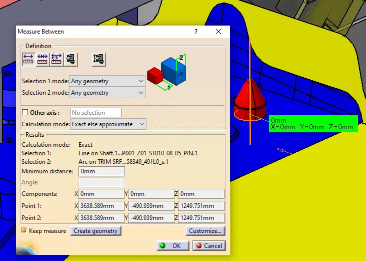
Fig(4.2)
The axis of the car panel hole and the axis of the pin should be same in general.
The pin tolerance for a geo pin will be of closer tolerence of -0.15mm & for the re-spot pin is -0.28mm.
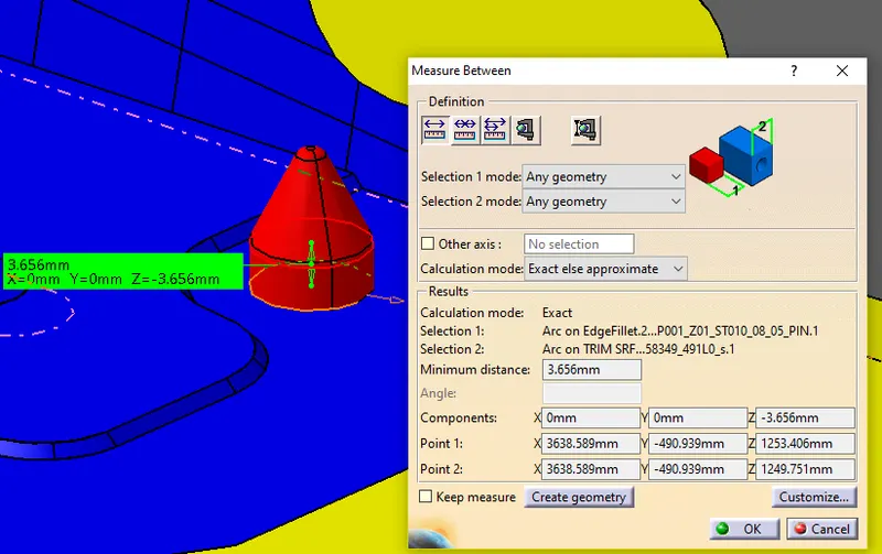
Fig(4.3)
- Pin should engage at 3 to 5 mm from car panel entry surface.
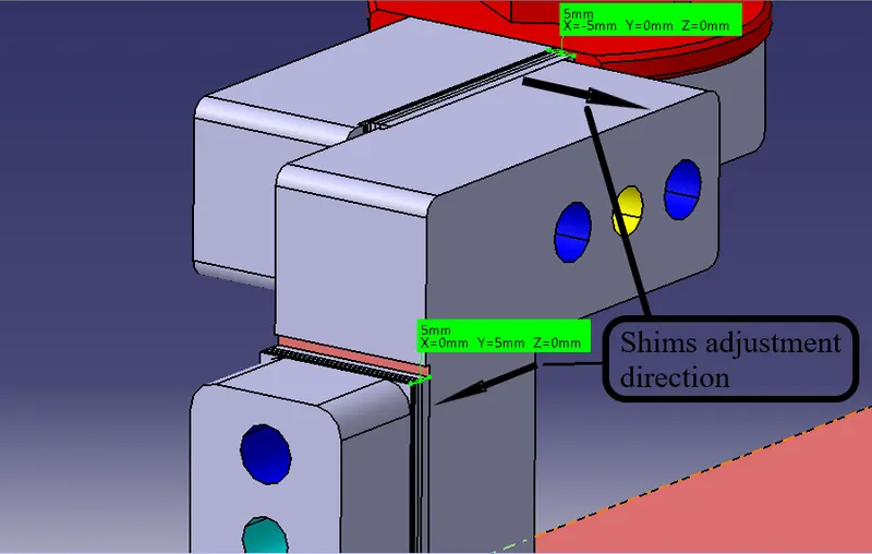
Fig(4.4): Shims
- All pins should be accommodated with 2-way adjustable shims irrespective of direction of arresting.
- Round pins should be used incase of 4way arresting of car part if the hole is round.
- Round pins can be used for 2 way arresting of car parts only if the hole is slotted.
- Diamond pins should be used for 2 way arrresting of car part if the hole is round.
- Diamond pins should be used incase of 4 way arresting of car parts if the hole is slotted.
Various parts of the pin unit:
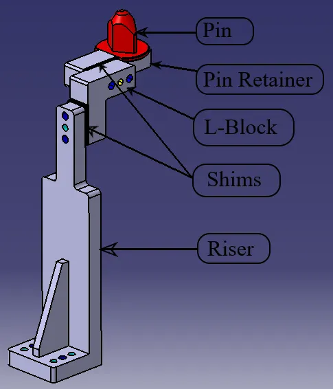
Fig(4.5): Parts of Pin Unit
Pin:
- Pin is the part which locates the car panel. It can be a make part or standard part.
- It should be grinding surface on shaft with fits onto which the the pin retainer will be fitted.
- The mounting surface of the pin should be fine machined surface.
- The pin should have a step machined surface to lock the rotation, which matches with the pin retainer.
- All machined planes should be perpendicular to the axis of the pin shaft.
- pin must have a provision like tapped hole from the bottom or a v-groove from the side.
- A pin must be hardened (Heat treatment) & black oxide finished in general.
Pin retainer:
- The pin retainer is a part which holds the pin in position, it can either be a make part or standard part.
- Pin retainer should have a hole with a fit, onto which the pin will be fixed.
- The pin mounting surface of the pin retainer should be a machined surface.
- The pin mounting surface of the pin retainer should have a step to lock the rotation of the pin.
- The surface of the pin retainer to the blocks should be a machined surface.
- The pin retainer will be fixed to a block or a L-block to the riser with 2 dowel holes(pins) & atleast with 1 screw hole to maintain the tolerance.
Block:
- Block is used to provide a 2 directional adjustment of pins with the help of shims.
- L-Blocks are most commonly used in general.
Shims/Spacers:
- Shims/Spacers are standard parts which are used for adjustments of locators (NC Blocks & Pin retainers) to get precise location of a pin with respect to car part.
- It helps to compensate for deviation in manufacturing processes.
Blade:
- Blade is a plate, which is used to mount assembly of pin, pin retainer & block on a riser.
- The blade can be either a designed part or a standard part.
Riser:
- It is a part on which all the parts are mounted and it is mounted on the base plate of the fixture.
A. Fixed Pin Unit: P001_Z01_ST010_02_00_FIX_PIN
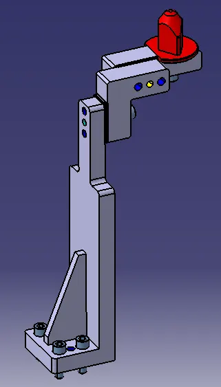
Fig(4.6): Fixed pin unit
3D finishing of Pin unit:
| Checking parameters | Action |
| Renaming & structuring the design tree | Done |
| Nominality of holes | Done |
| Hole concentricity | Checked |
| Hole standard colouring | Done |
| Butting of parts | Done |
| Machined area | Defined |
- Renaming & structuring of design tree:
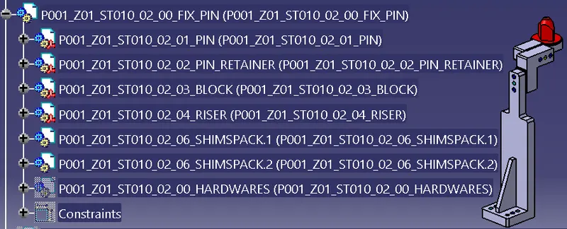
Fig(4.7)
- Hole concentricity & colouring standard:
Each hole is made concentric with respective hole of the mating parts.
Hole colouring standards:
- Threaded hole - Yellow colour
- Dowel hole - Blue colour
- Open hole - Cyan Green colour
- Machined area - Cream colour
- Relief area - Red colour
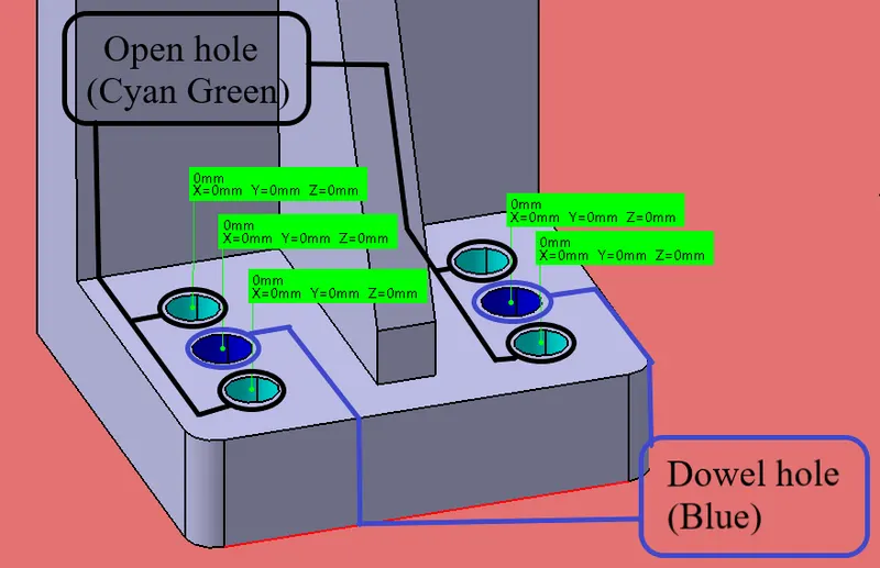
Fig(4.8)
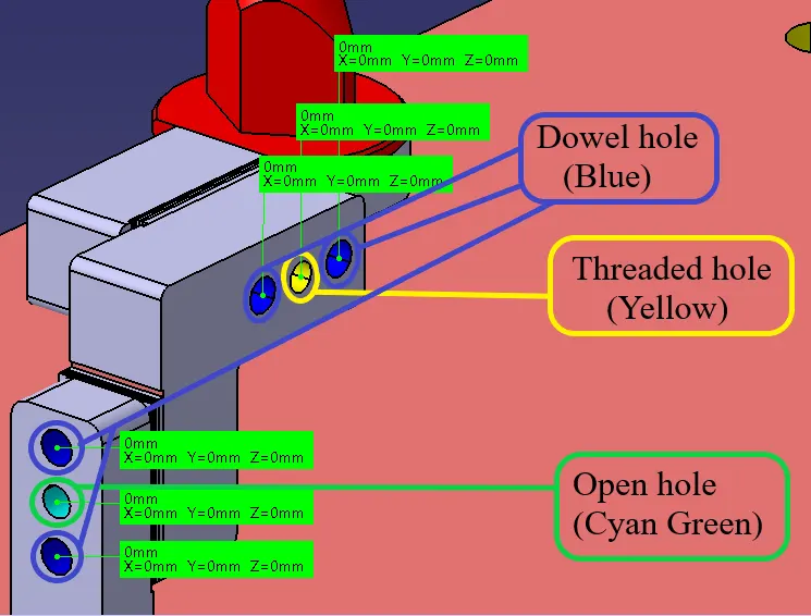
Fig(4.9)
- Butting of parts & Machining area:
Butting of all the mating parts are done and the required machining is provided for the respective mating part.
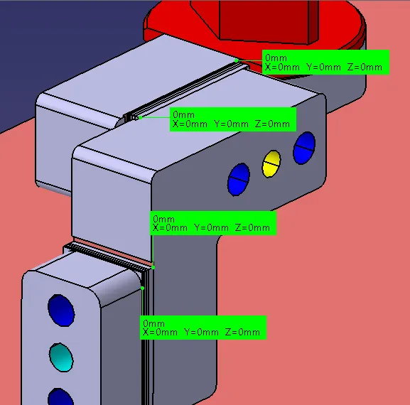
Fig(4.10)
Machined area is defined by cream colour and the relief area is defined by Red colour.
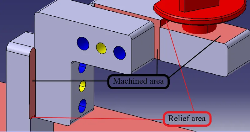
Fig(4.11): Machined area defined
- Fasteners implementation:
Fasteners are implemented as per the required size of the hole and checked for concentricity with the holes.
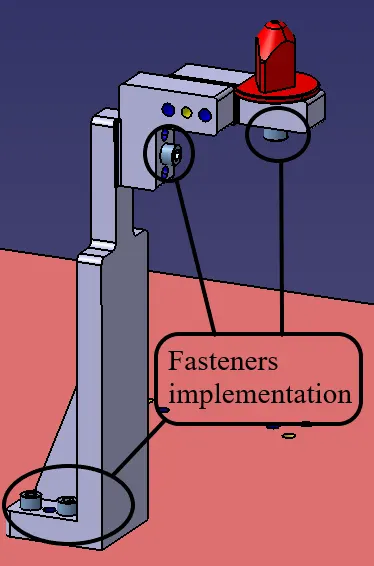
Fig(4.12)
B. Retractable Pin unit: P001_Z01_ST010_03_00_RETRACTABLE_PIN_UNIT ; P001_Z01_ST010_3.1_00_RETRACTABLE_PIN_UNIT
In this type of pin unit, a retractable cylinder is used to provide the pin move towards and away from the panel.
The retractable pin unit is accompanied with the rough locator for space constraints.
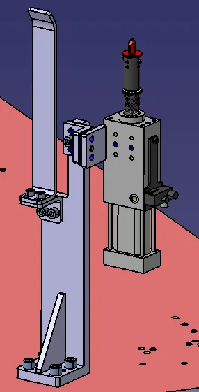
Fig(4.13):Retractable pin unit with rough locator
3D Finishing of the Retractable Pin unit:
| Checking parameters | Action |
| Renaming & structuring the design tree | Done |
| Nominality of holes | Done |
| Hole concentricity | Checked |
| Hole standard colouring | Done |
| Butting of parts | Done |
| Machined area | Defined |
- Renaming & structuring the design tree:
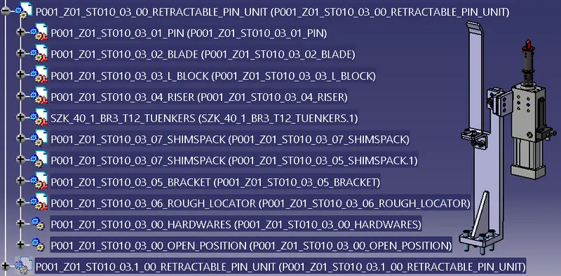
Fig(4.14): Design tree
- Hole concentricity & colour standard:
Each hole is made concentric with respective hole of the mating parts.
Hole colouring standards:
- Threaded hole - Yellow colour
- Dowel hole - Blue colour
- Open hole - Cyan Green colour
- Machined area - Cream colour
- Relief area - Red colour
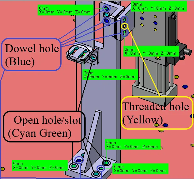
Fig(4.15)
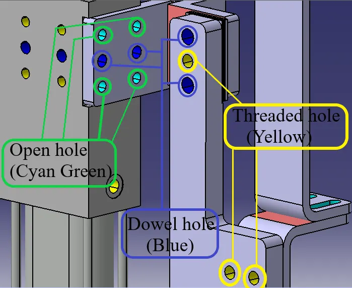
Fig(4.16)
- Butting of parts and Machining area:
Butting of all the mating parts are done and the required machining is provided for the respective mating part.
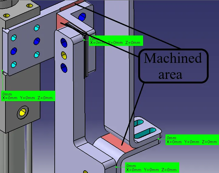
Fig(4.17)
Machined area is defined by cream colour and the relief area is defined by Red colour.
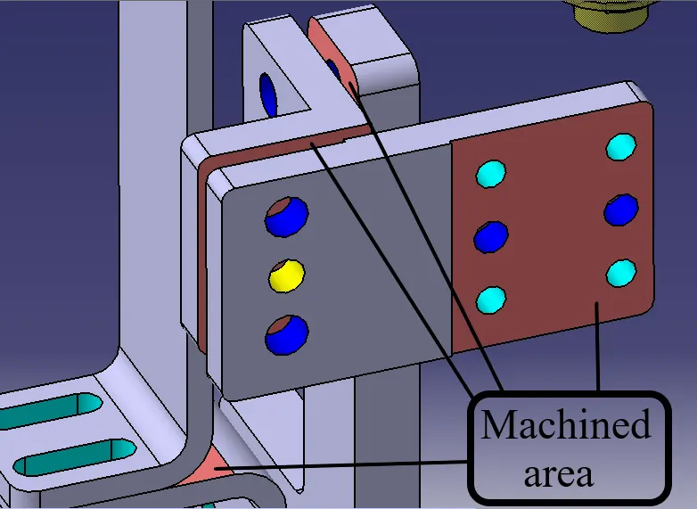
Fig(4.18)
- Fasteners implementation:
Fasteners are implemented as per the required size of the hole and checked for concentricity with the holes.
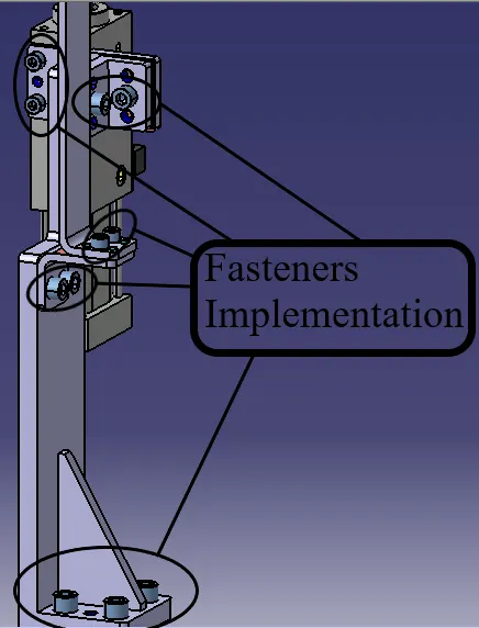

Fig(4.19) Fig(4.20)
Assembly of all pin units:
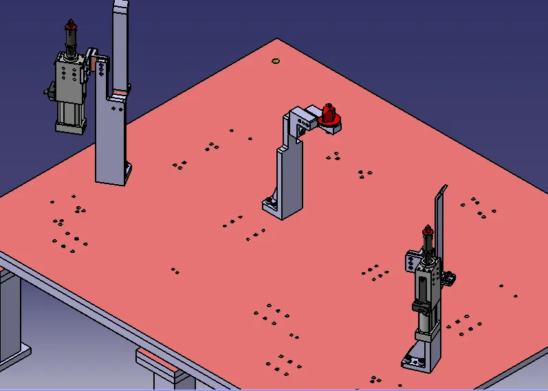
Fig(4.21): Position of Pin units
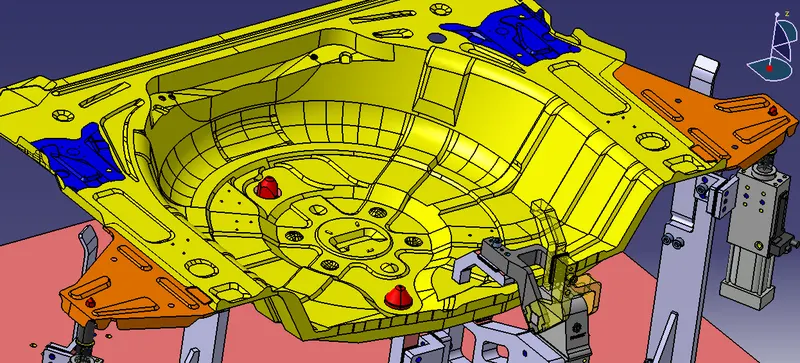
Fig(4.22): Assembly of all pin units
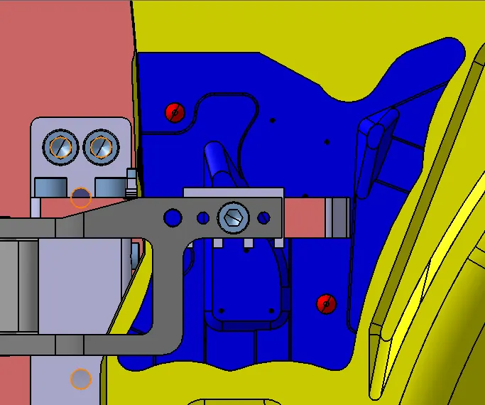
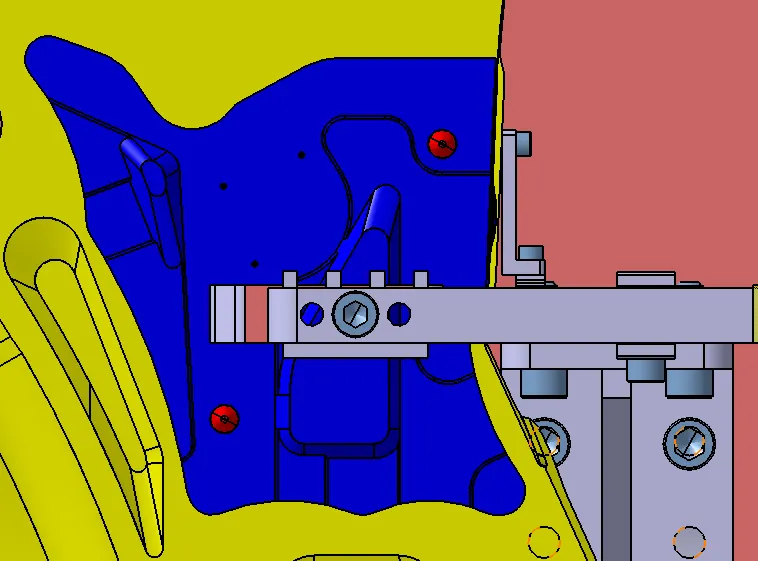
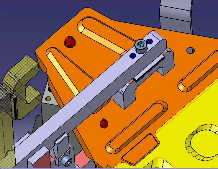
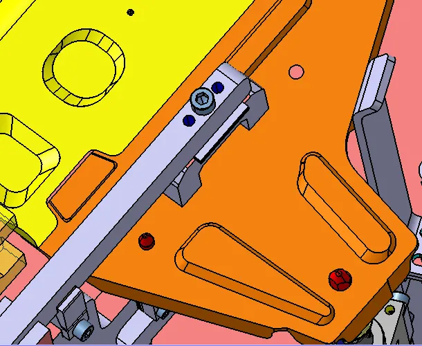
Fig shows: Various pins in the fixture assembled with car panel
5. Rest Unit: P001_Z01_ST010_11_00_REST_UNIT
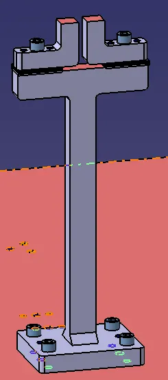
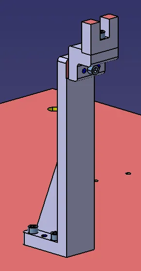
Fig(5.1): P001_Z01_ST010_11_00_REST_UNIT Fig(5.2): P001_Z01_ST010_12_00_REST_UNIT
- A rest unit is used to support the car panel, also it resists the clamping force of the finger with the help of rest mylars & thus clamps the car panel.
- Rest unit consists of rest mylars, shimpacks, riser.
- Holding force should be considered while designing a rest unit.
- Mostly to avoid excess part, to reduce the weight & to reduce the cost of the fixture the rest unit is combined with the clamp unit.
PURPOSE OF REST UNIT:
- The purpose of clamping tools is to securely hold the workpiece in position without obstructing the production process.
- It prevents the distortion during welding process and other processes.
- High clamping forces combined with compact dimensions are therfore the most important requirements for a clamping tool. For this reason, clamps are also equipped with mechanical transmission gear units.
Holding force:
- Holding force, on the other hand denotes the maximum force after locking the knee-lever (over centre position, that can be applied by the workpiece on the gripper/clamp arm without destroying the mechanism.
- Therefore, particular attention must be paid to the maximum holding force when, for example during the production process (welding, bonding), there is a possibility of distortion of the component or if the clamp arm is used as a fixed stop.
- If the holding force specified in the technical details is exceeded, this will inevitably result in the destruction of the mechanism, the clamp arm or the bearing position.
3D Finishing of Rest Unit:
| Checking parameters | Action |
| Renaming & structuring the design tree | Done |
| Nominality of holes | Done |
| Hole concentricity | Checked |
| Hole standard colouring | Done |
| Butting of parts | Done |
| Machined area | Defined |
- Renaming & structuring the design tree:
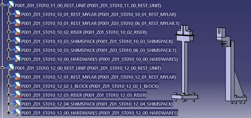
Fig(5.3): Design tree
- Nominality of holes:
The holes are made nominal to provide ease of assembly of the fixture.

Fig(5.4): Nominality of holes
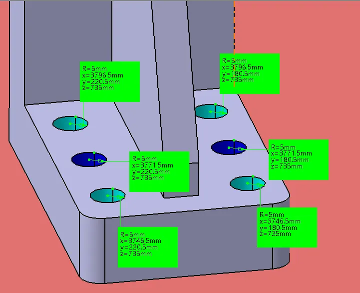
Fig(5.5): Nominality of holes
- Hole concentricity & colour standards:
Each hole is made concentric with respective hole of the mating parts.
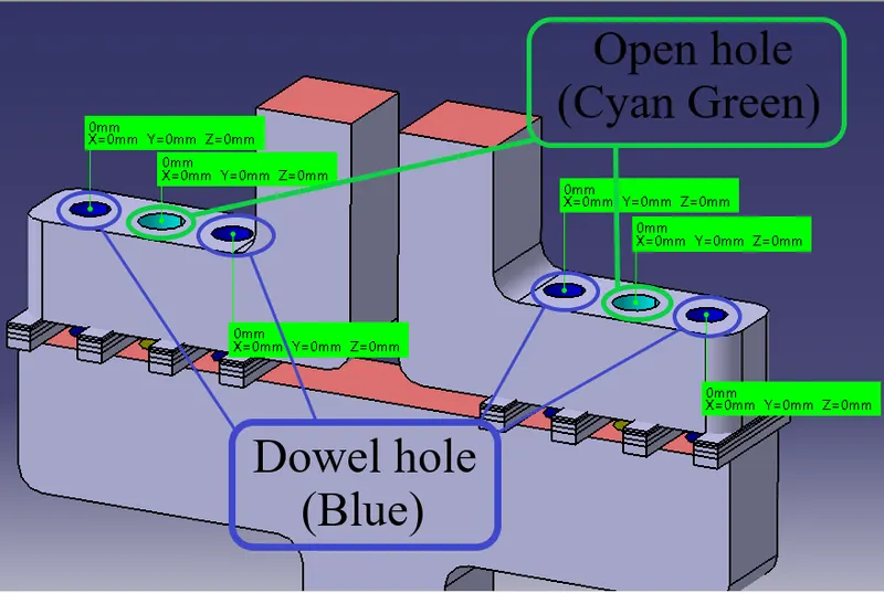
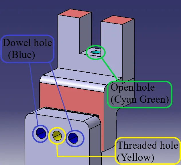
Hole colouring standards:
- Threaded hole - Yellow colour
- Dowel hole - Blue colour
- Open hole - Cyan Green colour
- Machined area - Cream colour
- Relief area - Red colour
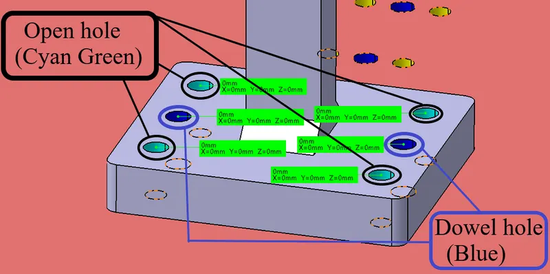
Fig(5.6)
Fig(5.7)
Fig(5.8)
- Butting of parts & machining area:
Butting of all the mating parts are done and the required machining is provided for the respective mating part.
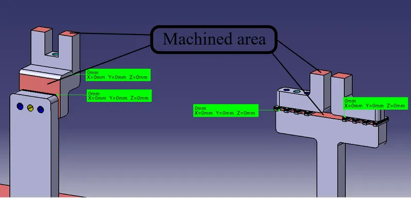
Fig(5.9)
Machined area is defined by cream colour and the relief area is defined by Red colour.
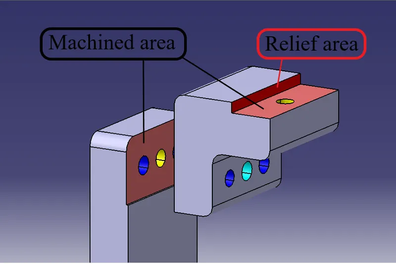
FIg(5.10)
6.FINAL ASSEMBLY VIEW:
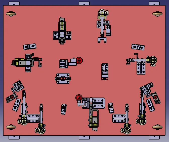
Fig(6.1): Position of all units
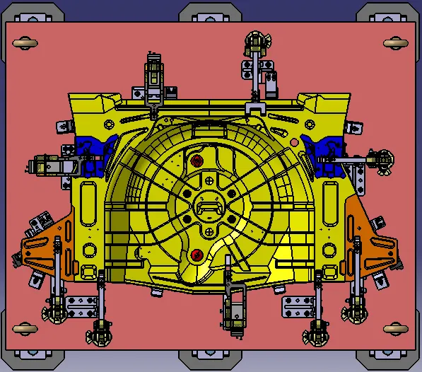
Fig(6.2): Position of units with car panel
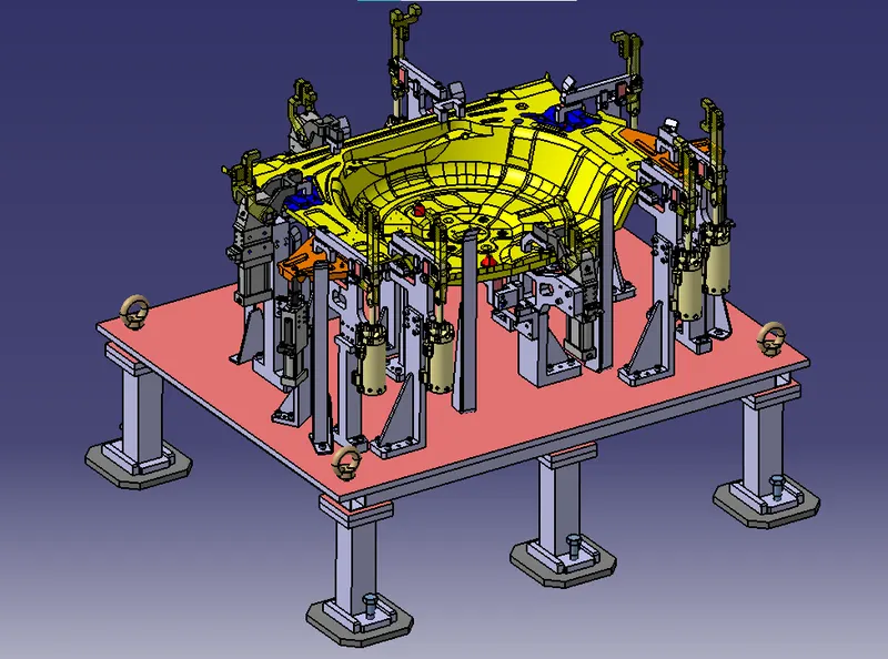
FIg(6.3): Assembly
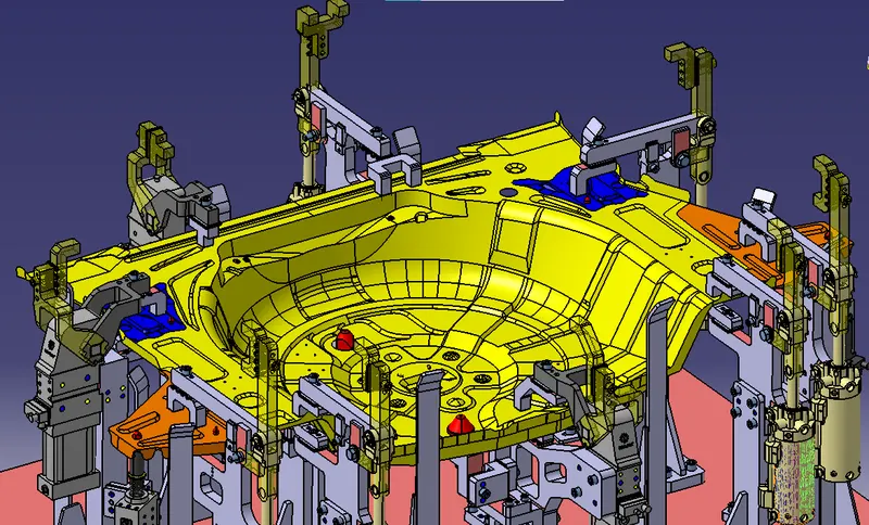
Fig(6.4)
Panel assembly:
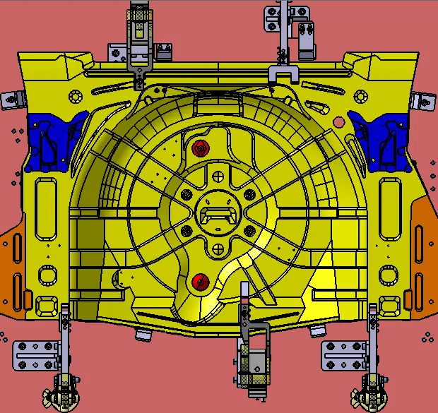
Fig(6.5): Assembly view of panel 1
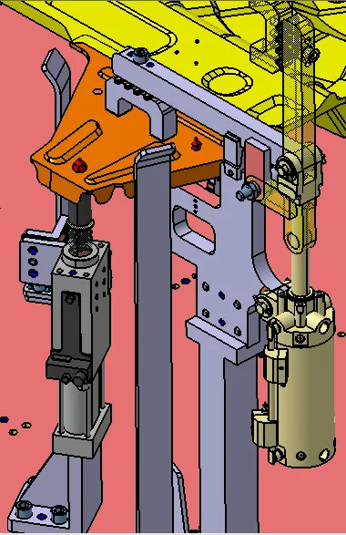
Fig(6.6): assembly view of panel 2&3
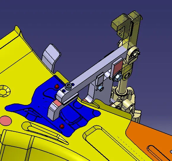
Fig(6.7): assembly view of panel 4
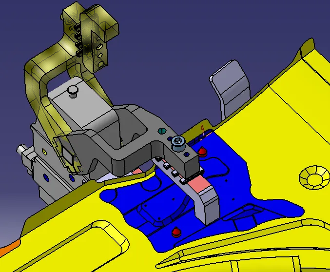
Fig(6.8): assembly view of panel 5
Conclusion:
Hence the 3D finish is done for the assembly and the rough locators are designed for the assembly fixture.