Week 7 State of charge estimation
Objective:
We have a BMS battery simulink model and simulate the model and prepare a detailed report on model and results.
Problem Statement:
We use the above link to download the simulink model for preparing the report. We download and open the file into simulink to run for results.
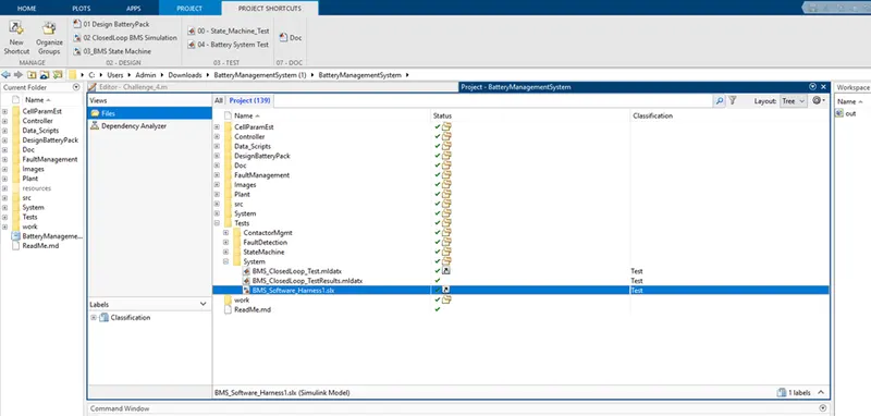
We import the simulink file into matlab
Tests==>system==>BMS_software_Harness
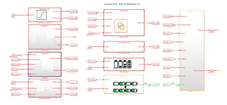
Simulink blocks used in the model:
- Test scenario selection blocks: Selection of test scenario state 1,2 or 3
- Indicating Lamps: Indication lamps are provided for the fault identification like over temperature, over voltage etc.
- BMS ECU: BMS ECU is a subsystem which takes two inputs like state request and feedback from the plant. This is generating output as BMS Output and Info which have current power limit calculation in State Machine, SOC estimation and Cell balancing logic.
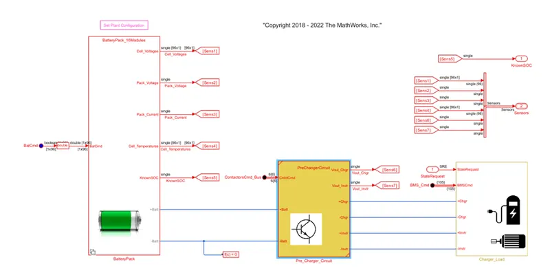
- Plant: Plant subsystem has a battery pack and it generate the output like pack current, SOC and voltage temperature.
‘
Tests Simulations:
Test series 1:
We run the simulink model selecting state request 1. The model take state request and sends it to both BMS ECU unit and Battery pack unit.
State one has following flow cycles:
- Driving mode for first 3000 sec.
- Cell balancing for next 1000 sec.
- Balance charging for the next 5000 sec.
- Post Charge balancing from 9000-20000 sec.
Results:
Found all lamp indications green indicating no fault.
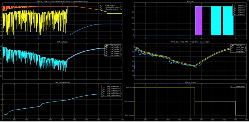
Observations:
Driving state:
- All the cells for the first 3000 sec are in driving state so the discharge of all the cells occurs and its voltage variations are in the range 3.1 to 3.9V (min and max).
- Cell temperature increases from 288K to 302K.
- SOC also reduces from 80% to 45%.
Balancing state (3000-4000 secs):
- For the next 1000 secs cell balancing occur and module are in standby mode and they maintain constant voltage 3.7V.
- Cell temperature reduces slowly as there is no current flow.
- SOC is also constant during this period at 45%.
Charging and balancing state (4000-9000 sec):
- After 4000 sec cell charging starts and the voltage increases from 3.7 to 4.2 volts at constant current flow rate of 30A, then constant voltage charging starts and current reduces from 30A to 2.5 A.
- Cell temperature increases exponentially till constant current charge and decreases as current decreases.
- SOC also increases from 45% to 94%.
Post Charge Balancing state (9000-20000 secs):
- After 9000 secs cell balancing starts at standby mode.
- Cell temperature reduces and tries to reach ambient temperature.
- SOC remains constant at 94%.
Test series 2:
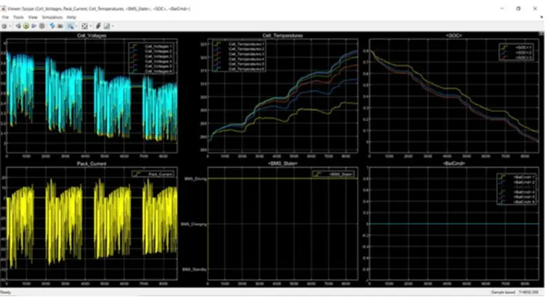
We select state request 2 and simulate the model. All indications lights found green and indicates no fault.
Observations:
Driving state (0-10000 secs):
- The cell voltage varies from 3.9 v to 3.05 volts which is cutoff voltage of cell and the entire cell is drained up to 8692 secs.
- Cell temperature varies from 288K to 323K.
- SOC reduces from 80% to 0 % as cell fully gets drained.
- In between standby modes are observed during driving cycle.
Test Series 3:
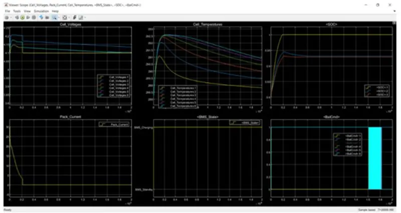
The model was simulated at state request 3. All lights were found green indicating no fault.
Observations:
Charging state (0-20000 secs):
- Cell voltage starts increasing from initial value and after 2000 secs it gets constant.
- Pack current initially starts from 0 to 30A and starts decreasing when the constant voltage mode is 2.5A and gets full charged by 2000 secs.
- Initial SOC was 80% and after 2000 secs it is 100%.
- Cell temperature starts increasing slowly when battery got fully charged then decrease down to ambient temperature.
- Balancing of all cells is done at end of simulation.
Question 2:
Explanation of coulomb counting n BMS battery model.
SOC is defined as rate of available capacity to its maximum capacity when a battery is fully charged and describes the remaining percentage of the battery capacity.
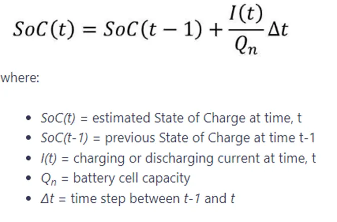
To find the SOC we use the coulomb counting method. The coulomb counting method measures the discharging current of the battery and integrates the discharging current over time in order to estimate SOC.
Which can be estimated from discharging current I(t), previously estimated SOC values (SOC(t-1)). The relation can be given as,
The state of charge (SoC) of a battery cell is required to maintain it’s safe operation and lifetime during charge, discharge and storage. However, SoC cannot be measured directly and is estimated from other measurements and known parameters. This leads to errors in the estimated SoC and that means it is not possible to fully exploit the full capability of the cell.
Coulomb counting gives a relative change in SoC and not an absolute SoC. If you measure the current over a given time step you have a measure of the number of Ah that have left or been received by the battery.

We use the same method for the estimation of SOC in our BMS model
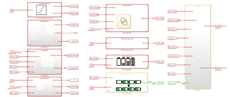
Coulomb counting equation simulated in BMS model as below,
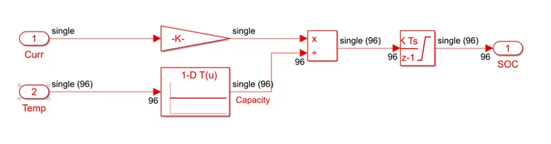
Here the discharge current from battery given to gain with value as 1/3600 to convert current to Ahr. The value is divided by capacity due to temperature change. Then integration with gain value of 1 with sample time -1 as we are using discrete integrator.
Saturation block limits value from 0 to 1. We get the SOC value from 0 to 1 multiplied with 100 to get in percentage of SOC.
Conclusion:
- The detailed project report was prepared and he results were plotted.
- The model was simulated for all 3 test conditions and results were obtained.
- The results were explained in detail.