Week 7 State of charge estimation
AIM:
To simulate Simulink model “Design and Test Lithium-Ion Battery Management Algorithms” and interpret the results.
Objective:
- To Simulate the 3 test cases from the harness dashboard and write a detailed report on the results for the given MATLAB model.
- What is coulomb counting? Refer to the above model and explain how BMS implements coulomb counting for SOC estimation?
Description:
Before going to run the model, let us understand a bit about test harness and battery management.
Test Harness:
A test harness is a model that isolates the component under test, with inputs, outputs, and verification blocks configured for testing scenarios. We can create a test harness for a model component or for a full model. A test harness gives you a separate testing environment for a model or a model component.
Battery management system (BMS):
It is an electronic system that manages a rechargeable battery (cell or battery pack), such as by protecting the battery from operating outside its safe operating area, monitoring its state, calculating secondary data, reporting that data, controlling its environment, authenticating it, and balancing it.
The Simulink model is downloaded from the following the link:
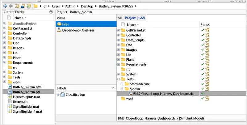
Initially, the folder to be loaded in the MATLAB and the project file has to be opened. Once that is opened, the file under the system folder to be opened to see the dashboard.
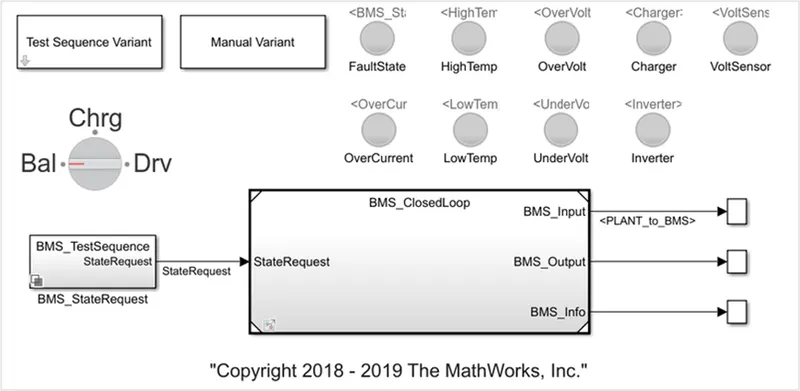
In the above figure we can see the different block which perform different functions. Which are explained below.
Test Sequence Variant block is used to choose the test case.
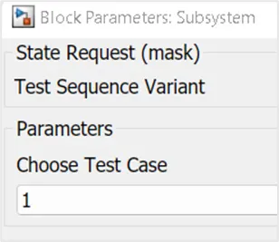
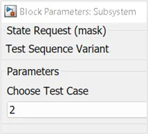
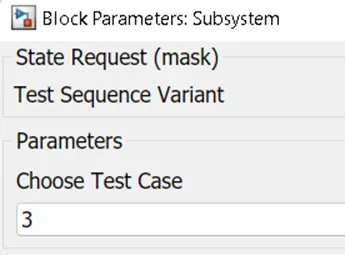
Manual variant is used to operate manually under certain situations. The following figure shows the test sequence variant block subsystem to choose the tests.
Let us select the first test case and see what’s inside it:
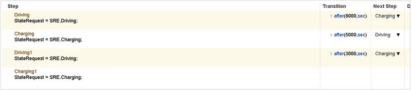
Let us look into BMS_State request block, Under first test case selection, it is shown as below:
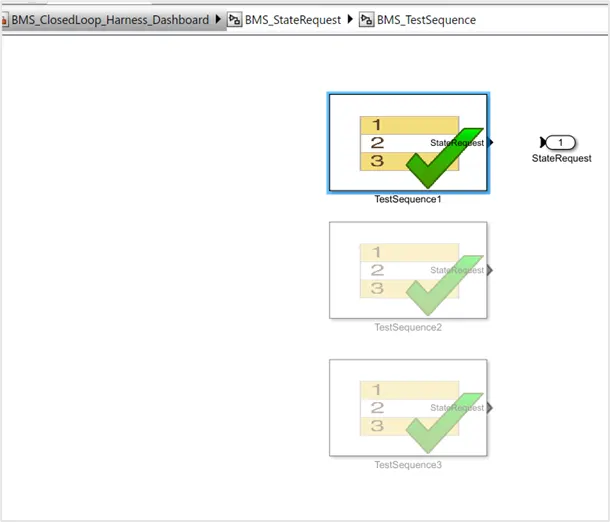
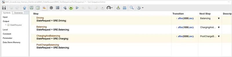
In the first test case, we can see that the above steps that are executed for certain time period.
The lamp blocks in the dashboard will indicate the status of the battery pack in the working condition. If everything is good then all the lights will be in green colour, if there is any fault then it will turn to red colour.
Test case 1:
The drive cycle in this case is as follows:
- Driving for the first 3000 secs
- After 3000 sec starts balancing operations occur for the next 1000 secs
- Then charging and balancing occurs for the next 5000 secs
- After that sequence post charge, a balancing operation occurs till the end of the simulation period.
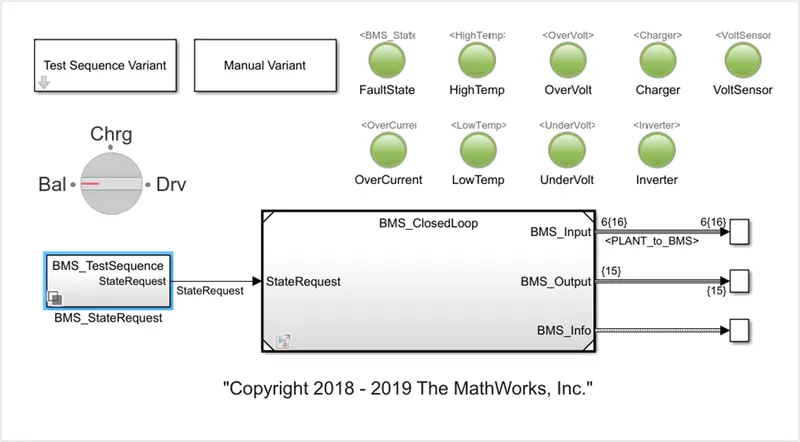
The lamp indication is showing green for the overall simulation period showing that there are no faults occurs the sequence.
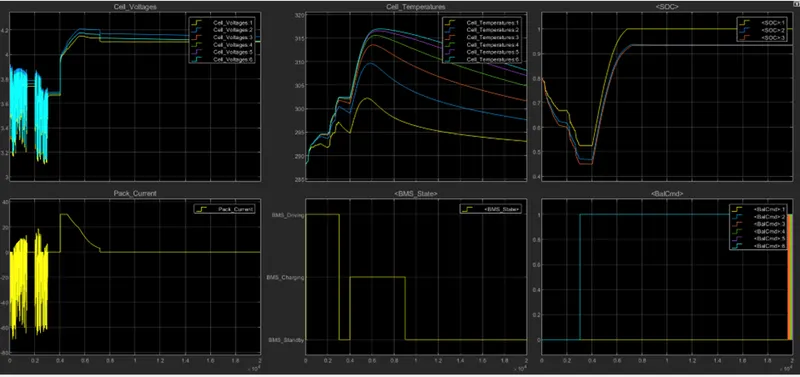
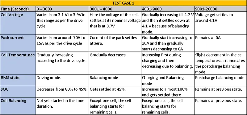
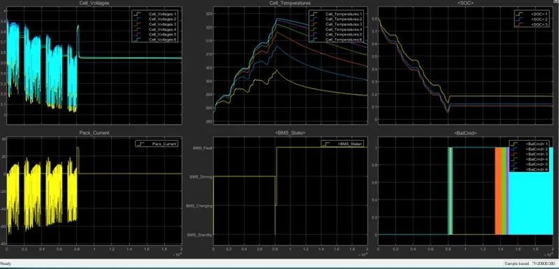
In the above plot we can observe the parameters like Cell voltage, Cell temperatures, SOC, pack current, BMS state and Bal cmd.
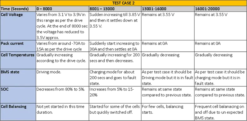
Test case 2:
The drive cycle in this case is modified as follows:
- Driving for the first 8000 secs
- Charging for next 5000 secs
- Driving for next 3000 secs
- Charging for rest of the time.
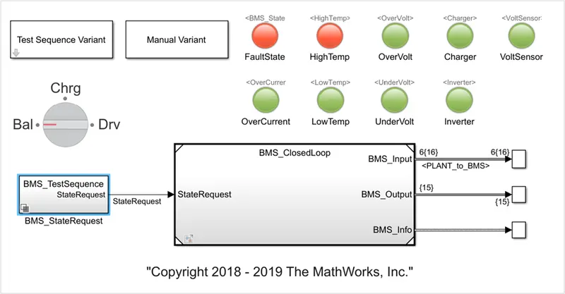
The lamp indication is showing red for the fault state and high temperature. Let us see what happened in this case.
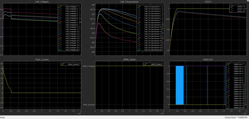
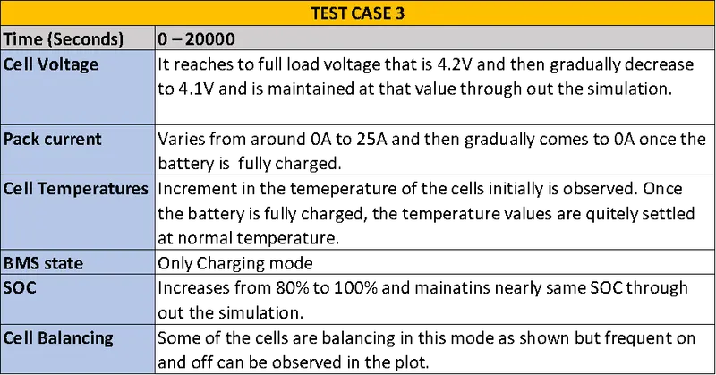
Test case 3 :
The drive cycle in this case is as follows:
- Charging for 20000 secs

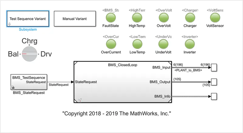
All lamps are green that means no fault in this test case. Let us plot now.
Coulomb Counting:
Coulomb counting is a technique used to track the state of charge of a battery pack.
It works by integrating the active flowing current (measured in amps) over time to derive the total sum of energy entering or leaving the battery pack. This produces a capacity that is typically measured in amp-hours [Ah]
The coulomb counting method measures the discharging current of a battery and integrates the discharging current over time to estimate SOC.
It’s done to estimate the SOC(t) which is estimated from the discharging current I(t) and previously estimated SOC values Soc(t-1). SOC is calculated by the following equation;
soc(t)=soc(t-1) + [I(t)/Qn]*dt
where as,
SOC(t)= state of charge at the estimated time.
I(t)= discharging current.
Qn= nominal battery capacity
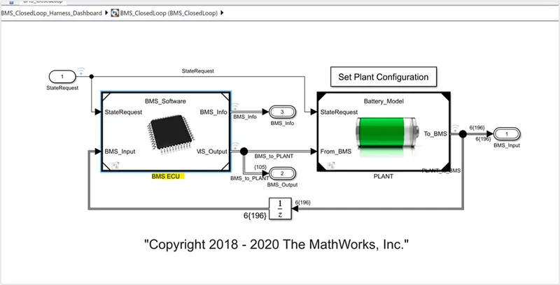
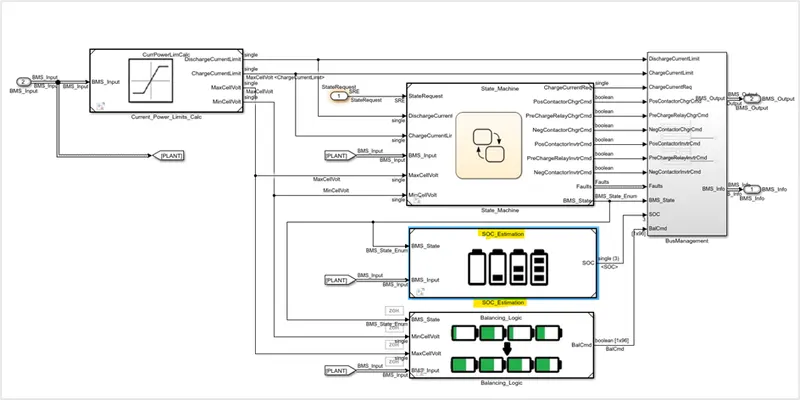
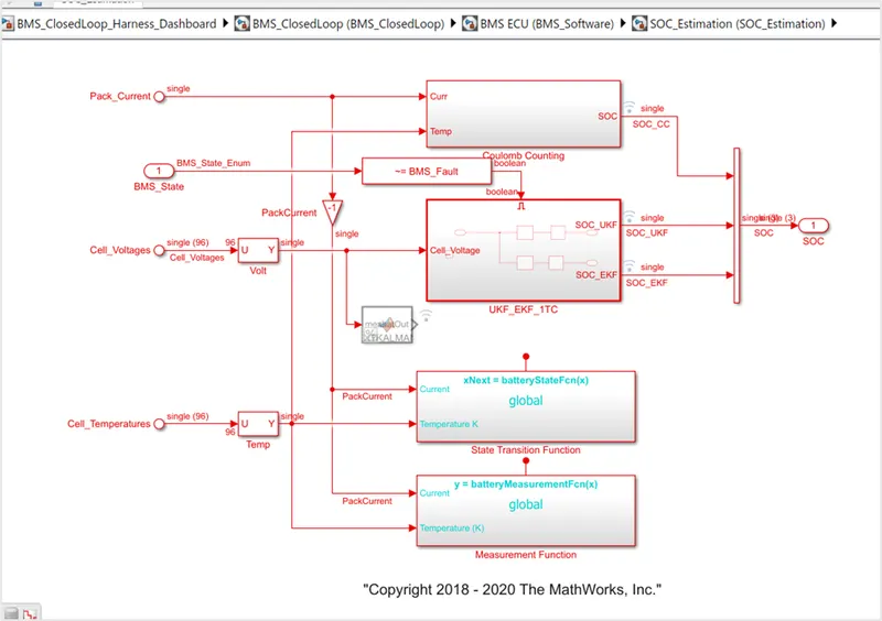
By navigating though following path, we get into the coulomb counting model.
BMS_ClosedLoop_Harness_Dashboard/BMS_ClosedLoop (BMS_ClosedLoop)/BMS ECU (BMS_Software)/SOC_Estimation (SOC_Estimation)/Coulomb Counting
In the SOC estimation block we can see that various methods to estimate the SOC. In this the first block represents the coulomb counting method. The following figure shows the system under Coulomb counting method.
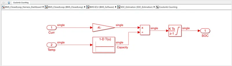
The current and temperature parameters of the cells are given as inputs to gain block and 1-D lookup table respectively. The lookup table gives the capacity over the time. The capacity will vary with respect to the temperature. Now these outputs from the gain block and look up table is given to the product block. It is then given to the discrete time integrator block which performs the integration operation and gives the value of SOC.
The accuracy of this method is not very high. The main advantage of Coulomb counting is its simplicity, easy implementation and low computational cost.
Conclusion: Thus the 3 test cases of Simulink model “Design and Test Lithium-Ion Battery Management Algorithms” is run and studied the results.