Week -2
AIM:
- To make a Simulink model of Doorbell using solenoid block
- To use thermistor to sense the temperature of a heater and turn off the fan.
OBJECTIVES:
- Doorbell: Create a Simulink model where the switch is closed for 2 seconds and then released. Observe the physical movement of the plunger by assuming remaining parameters.
- Thermistor: Create a Simulink model where the thermistor is used to sense the temperature with following conditions:
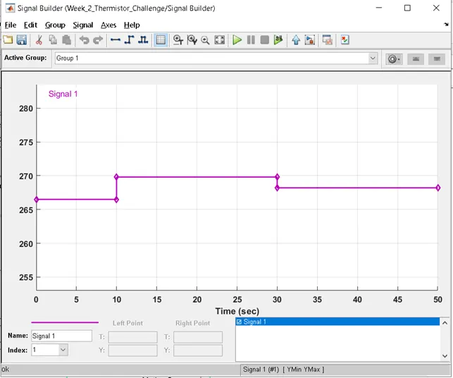
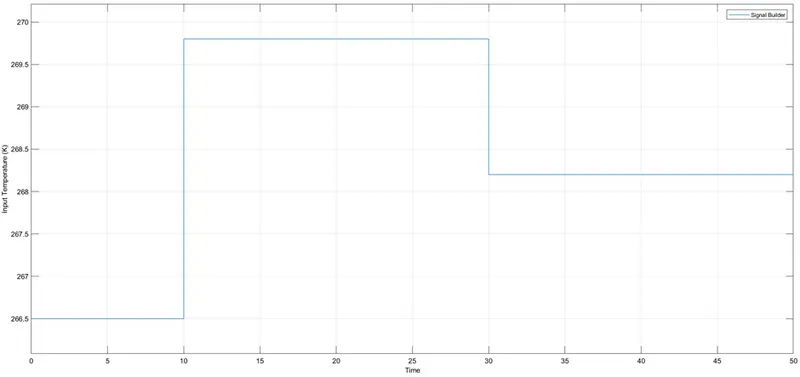
Temperature source: 20 °C from 0 to 10 seconds, 27 °C from 10 to 30 seconds, 23 °C from 30 to 50 seconds. Fan conditions: ON if the temperature above 25 °C, OFF otherwise
How does a doorbell work?
Consider a typical doorbell as shown in below image. It has mostly a power source, switch, solenoid (Iron piece with windings), gong and a spring-loaded arm/plunger.
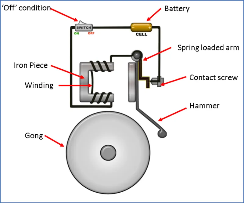
Figure 1: Parts of a typical door bell
When the switch is in ‘on’ condition, the electromagnet receives electrical power from the battery and pulls the metal arm to hit the bell producing sound. See below image for pictorial representation.
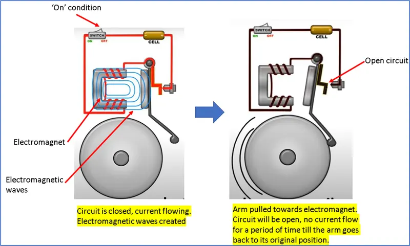
Figure 2: Working principle of a typical door bell
In a similar way as explained in above example, a door bell with solenoid also works.
Solenoid: A solenoid is a type of electromagnet, the purpose of which is to generate a controlled magnetic field through a coil wound into a tightly packed helix.
A solenoid actuator mainly consists of a case, winding, spring/damper, rod/plunger. Upon providing the input current to solenoid, the plunger gets attracted/repulsed towards the left dead centre thus creating a linear motion.
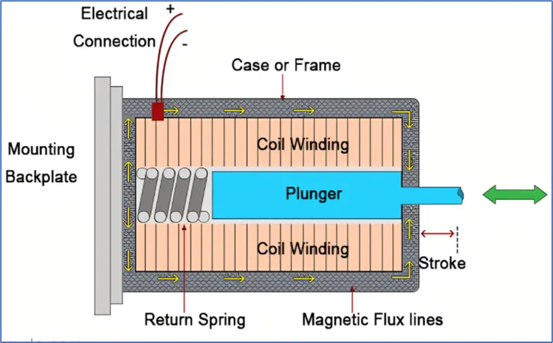
Figure 3: Solenoid actuator parts
Simulink model of Doorbell using solenoid block:
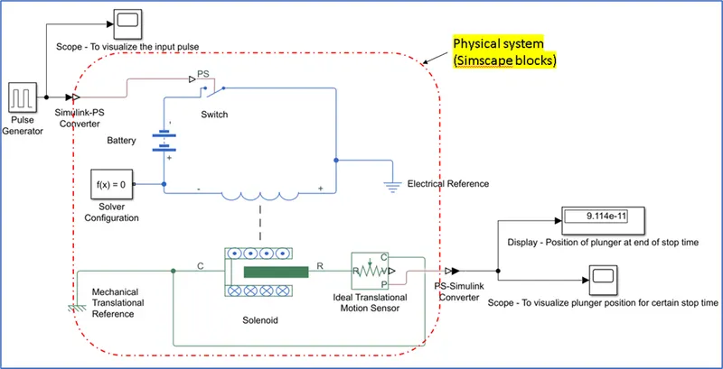
Figure 4: Simulink model of Doorbell using solenoid block
Blocks used in this model:
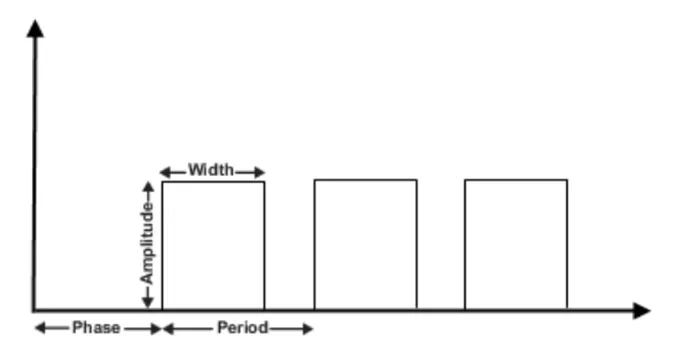
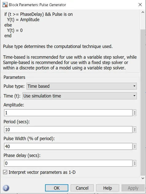
Pulse generator: The Pulse Generator block generates square wave pulses at regular intervals. The block waveform parameters, Amplitude, Pulse Width, Period, and Phase delay, determine the shape of the output waveform. The following diagram shows how each parameter affects the waveform.
Simulink to PS converter: The Simulink-PS Converter block converts the input Simulink signal into a physical signal. This block is used to connect Simulink sources or other Simulink blocks to the inputs of a Simscape physical network.
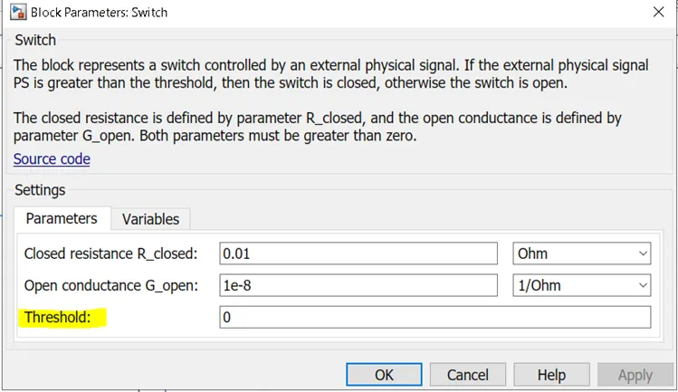
PS switch: This Switch block models a switch controlled by an external physical signal. If the external physical signal (PS) is greater than the value specified in the Threshold parameter, then the switch is closed, otherwise the switch is open. See appendix for more details about switch and its types.
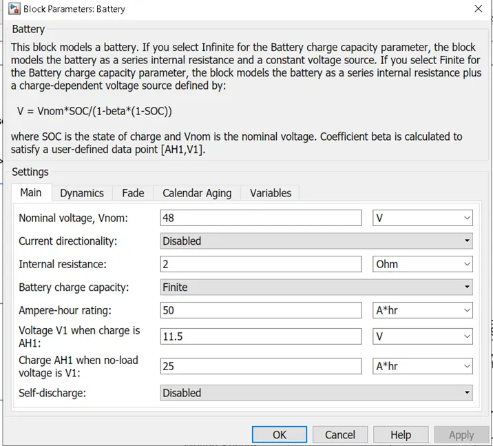
Battery: The Battery block represents a simple battery model with different settings where we can control the parameters as shown in below image.
Electrical reference: The Electrical Reference block represents an electrical ground. Electrical conserving ports of all the blocks that are directly connected to ground must be connected to an Electrical Reference block. A model with electrical elements must contain at least one Electrical Reference block.
Solver Configuration: Each physical network represented by a connected Simscape block diagram requires solver settings information for simulation. The Solver Configuration block specifies the solver parameters that your model needs before you can begin simulation.
Each topologically distinct Simscape block diagram requires exactly one Solver Configuration block to be connected to it.
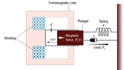
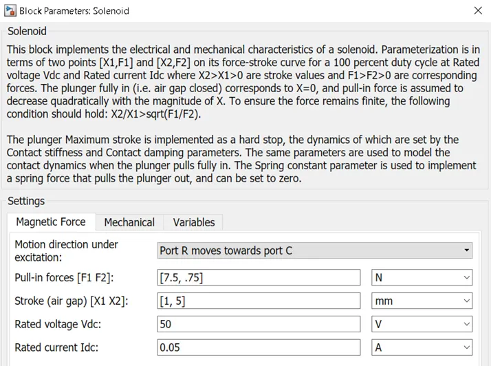
Solenoid block: The Solenoid block represents the electrical characteristics and generated force for the solenoid in the following figure
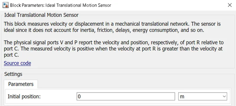
Ideal Translational Motion Sensor: The Ideal Translational Motion Sensor block represents a device that converts an across variable measured between two mechanical translational nodes into a control signal proportional to velocity or position. You can specify the initial position (offset) as a block parameter.
The sensor is ideal since it does not account for inertia, friction, delays, energy consumption, and so on.
Mechanical Translational reference: The Mechanical Translational Reference block represents a reference point, or frame, for all mechanical translational ports. All translational ports that are rigidly clamped to the frame (ground) must be connected to a Mechanical Translational Reference block.
PS-Simulink Converter: The PS-Simulink Converter block converts a physical signal into a Simulink output signal. Use this block to connect outputs of a Simscape physical network to Simulink scopes or other Simulink blocks.
Scope: The Simulink Scope block display time domain signals.
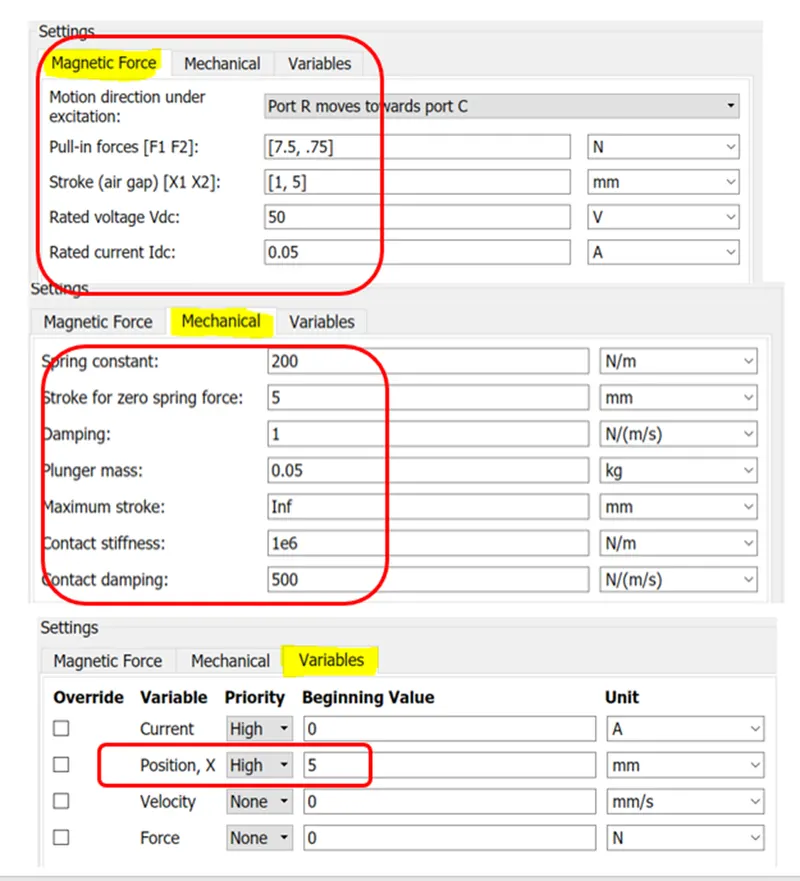
Solenoid block configuration:
EXPLANATION:
- To create a model that represents working of a door bell using Simulink, we firstly need solenoid block. This block needs a power source from where it can get the power.
- This Solenoid can be controlled by using a mechanical switch. That means when the switch is ‘on’, the solenoid starts functioning.
- Firstly, a pulse generator is called to create square wave pulses at regular intervals. These pulses can be controlled by varying the parameters like Amplitude, period, pulse width in the ‘pulse block’.
- Since the solenoid block comes under ‘Simscape’ environment (Physical system) and ‘Pulse generator’ is in Simulink environment, a ‘Simulink-PS converter’ block is connected to the pulse generator to convert signals from Simulink to PS.
- These signals are then connected to a PS-switch. The PS-switch is controlled by an external physical signal. If the external physical signal PS is greater than the threshold, then the switch is closed, otherwise the switch is open. In our case, the amplitude of the pulse is set to ‘1’ and threshold in switch is set to ‘0’.
- A battery is connected in series with the switch and the terminals of the battery is then connected to solenoid terminals.
- An electrical resistance shall be connected anywhere in this electrical circuit.
- The plunger in the solenoid gets actuated if the switch is in closed position. The movement(position) of the plunger can be observed using the ‘scope’ block. In order to observe the position or velocity of the plunger, we need an ‘Ideal translational sensor’ and a ‘PS-Simulink converter block.
- The position is thus visualized in the ‘scope’ block for a certain period of stop time.
- Solenoid is an electro-mechanical block thus it also needs mechanical translational reference.
- Most importantly, a solver configuration block must be connected at any part of physical system to solve the model.
Plots:
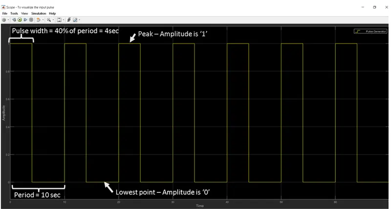
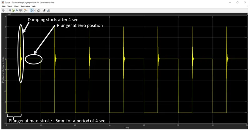
Observations:
- The battery terminals can be connected in any fashion to solenoid and it doesn’t make any difference in the result.
- The battery voltage and its other parameters are kept as constant during the run.
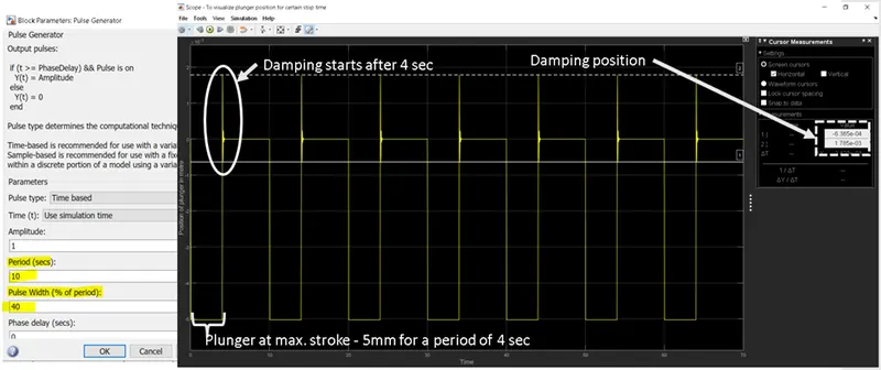
- The plunger is at maximum stroke when the switch is closed for a period of 4 sec (pulse width) and right after 4 sec, the damping of the plunger starts and brings it to rest position. It means with in 6 seconds, the solenoid has to adjust and bring the plunger to rest position before going back to its maximum stroke. This is repeated for 70 seconds in this case.
- With the assumed damping parameters in the solenoid block, what we can observe from the plot is: the damping starts from 3mm to -2mm and then gradually move towards 0 (rest position).
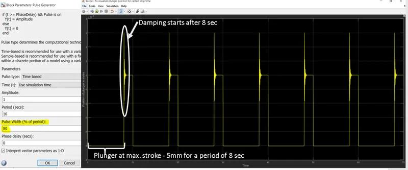
- Case 1: Let us try to vary the pulse width and see how it impacts the plunger movement. From the below plot, it can be observed that there is no changing in damping positions.
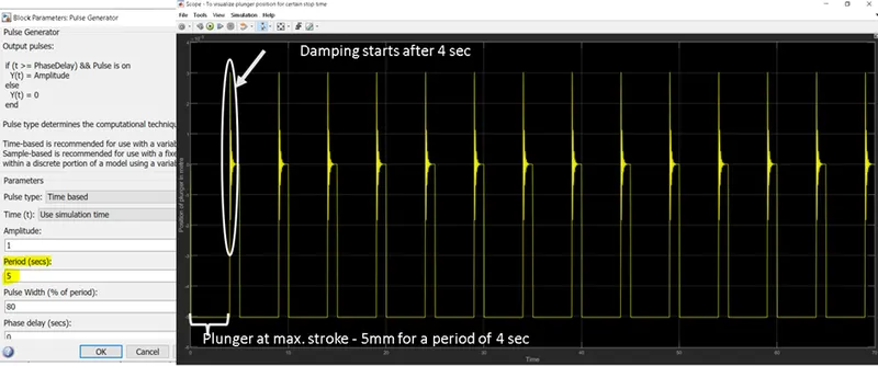
- Case 2: Let us try to change the period to 5 sec instead of 10 sec (in above case) by keeping pulse width same as above case and see what happens. The plunger is at maximum stroke for 4sec and with in 1sec, the system has to damp before going back to its maximum stroke. Also, there is no change in damping position.
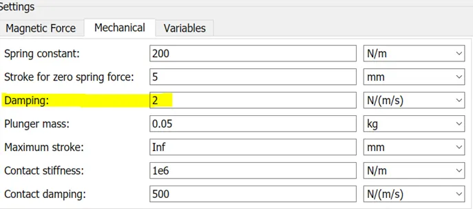
- Case 3: Now, by observing from the above 2 plots, let us try to bring out an optimized plot by giving sufficient time to damp and control the damping position by increasing damping value. The plunger is at maximum stroke for 4sec and it has 6 sec to damp and come to rest before going back to max. stroke. We can observe that there is a change in damping position as well due to the increase in damping coefficient.
Conclusion:
- By varying the period and pulse width of a pulse, the time duration of the plunger at its maximum stroke increases/decreases and time needed for damping the plunger increases/decreases.
- By increasing the damping coefficient, the damping position can be controlled and time taken to damp can be brought down.
- Thermistor challenge:
Thermistor: The term thermistor comes from “thermal” and “resistor”. A thermistor is a type of resistor whose resistance is reliant on temperature; it’s a resistance thermometer. They’re made from metallic oxide which is moulded into a bead, disk, or cylindrical shape and then enclosed with epoxy or glass.
There are two types of thermistors – the most commonly used is the Negative Temperature Coefficient (NTC) thermistor. The NTC’s resistance decreases as the temperature increases, and vice versa. With the Positive Temperature Coefficient (PTC) thermistor, the resistance increases as the temperature increases, and vice versa; it’s normally used as a fuse.
The change in resistance needs to be converted to temperature, which then produces measurable data.
In summary, Thermistors change resistance with temperature changes; they are temperature-dependent resistors. They’re perfectly suited to scenarios where one specific temperature needs to be maintained, they’re sensitive to small changes in temperature.
The below Simulink model is created to use a thermistor to sense the temperature of a heater & turn on or turn off the fan/motor as per the below conditions:
|
Time (seconds) |
Temperature (Celsius) |
Temperature (Kelvin) |
|
0-10 |
20 |
266.5 |
|
10-30 |
27 |
270.4 |
|
30-50 |
23 |
268.2 |
Fan conditions: ON if the temperature above 25 °C (269.3K), OFF otherwise.
The blocks used in this model are:
Signal Builder: To generate the signal according to the given input
PS-Simulink converter: Converts Simulink signals to the respective physical signal.
Controlled temperature source: Provides a temperature physical output based on the condition given to port S.
Thermal reference: This block provides the required initial conditions to the connected thermal block for the solver.
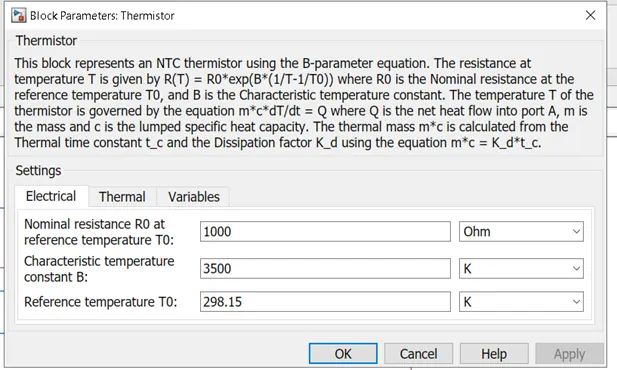
Thermistor: The block used here is a NTC thermistor. Default values are considered here.
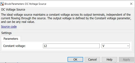
DC voltage source: The ideal voltage source maintains a constant voltage across its output terminals, independent of the current flowing through the source. The output voltage is defined by the Constant voltage parameter, and can be any real value.
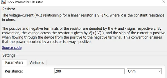
Resistor: It provides the opposing nature of current in circuit.
Voltage sensor: This is used to measure the voltage across any electrical component and connected parallel to the component. It has a physical signal port that outputs voltage value.
Electrical reference: These domain-specific electrical reference blocks will provide the required initial conditions to the connected electrical block for the solver.
Solver configuration: This block specifies the solver parameters that our model needs before you can begin simulation and is mandatory for simscape designs.
PS-Simulink converter: Converts physical signals to respective Simulink signal.
Constant: Provides a constant output value.
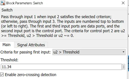
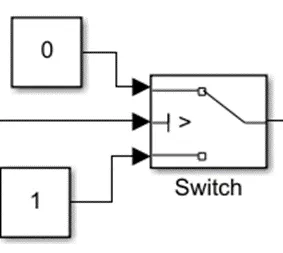
Switch: The switch used in this case has three input ports: Port 1, Port 2, Port 3. Port 2 is a control input where the signal given to Port 2 is satisfied with the condition and threshold of the switch block then it passes Port 1 as output and if it is not satisfied then it will pass Port 3 as output.
Scope: This is an output block that shows the signal with respective time in X-axis.
Controlled voltage source: This block is an ideal voltage source that gives a constant output based on the load requirement connected to it.
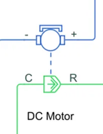
DC motor: It is an electromechanical block that takes an electrical input and provides mechanical rotational output. In this model, all default values are maintained.
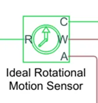
Ideal rotational motion sensor: This block is a motion sensor that senses the rotational output from the mechanical rotational blocks. The physical signal ports W and A report the angular velocity and angle, respectively, of port R relative to port C.
Mechanical rotational reference: This block represents a mechanical rotational reference point, that is, a frame or a ground.
Main model:
Explanation:
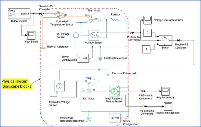
- The input signal is generated with ‘Signal builder’ block and provided as input to ‘controlled temperature source’ via ‘Simulink –PS converter’ block.
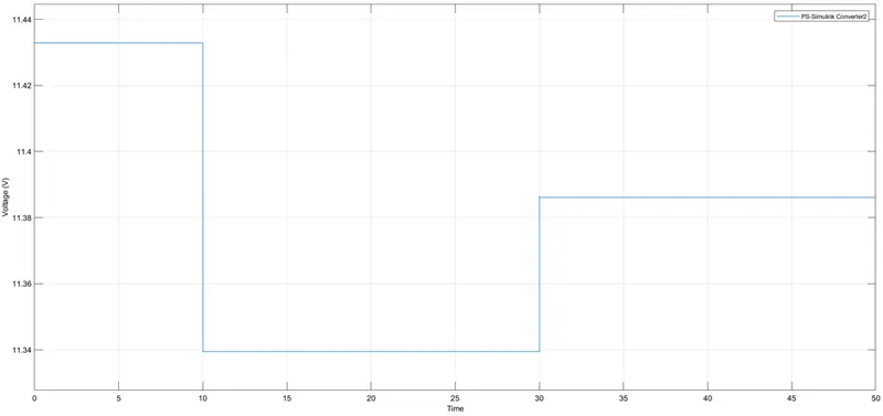
- The output from temperature source is thus connected to Thermistor (NTC) to see how the thermistor’s resistance/voltage varies with respect to temperature.
- A DC voltage source is connected in the circuit, a voltage sensor is connected in parallel with thermistor to measure the voltage across the thermistor. A resistor is connected in the circuit to provide some resistance to the flowing current.
- An electrical reference is connected to this electric circuit and a solver configuration is connected that specifies the solver parameters.
- The physical signal port from ‘voltage sensor’ is connected to Port 2 of a switch via ‘PS-Simulink converter’.
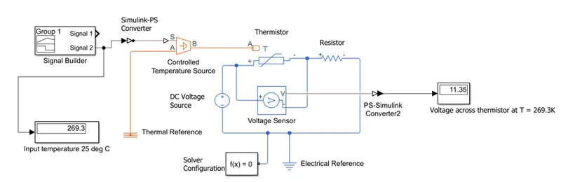
- The threshold value in the switch is set to 11.35V (This is derived by using another model for temperature 25°C, see below model). When the input signal is greater than threshold then Port 1 is connected else Port 2 is connected.
- Since the output signal is in Simulink environment, it is converted to physical system and then connected to controlled voltage source.
- The terminals of the ‘controlled voltage source is connected to a DC motor. The ‘C’ port is connected to ‘mechanical rotational reference’ and ‘R’ port is connected to a ‘Ideal rotational motion sensor’.
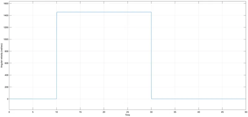
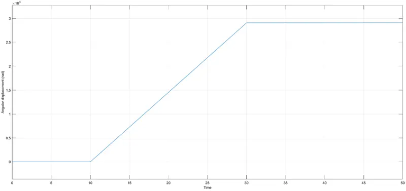
- The ideal rotational sensor has two outputs: Angular velocity and Angular displacement where we can see the signals for respective time period.
- Following are the plots obtained from this simulation:
Input plot:
Voltage across the thermistor:
Angular velocity of the motor shaft:
Angular displacement of the motor shaft:
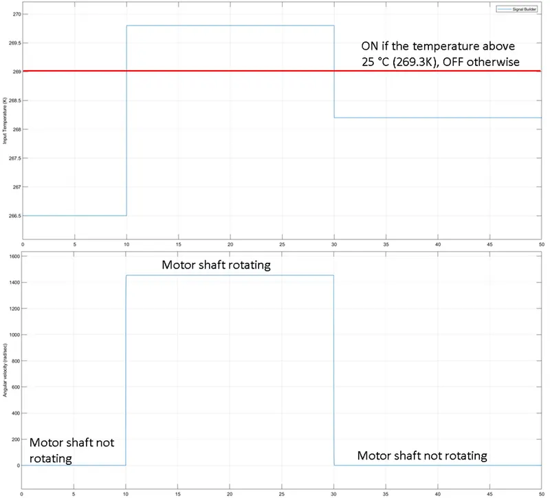
Observations made from the plots:
- For the time period 0-10 seconds and 30-50 seconds: the motor shaft is not rotating because of the logic provided at the switch.
- For the time period 10-30 seconds: the motor shaft is rotating because the input temperature was greater than 25 °C (269.3K).
- From voltage plot, we can see that the voltage is dropping when the temperature is high.
- From the angular displacement plot, we can see that the motor shaft was not rotating for first 10 seconds and the next 20 seconds the rotor shaft is rotated by some radians and for the final 20 seconds the shaft stops rotating.
Conclusion:
A thermistor can be used to vary the resistance in the circuit with the effect of temperature on it. This resistance can be used as an output to control the necessary electrical components as per the requirement.
Link for the Simulink files:
https://drive.google.com/drive/folders/1TxIh7GvClckbfybqea3SRpd6qlgQWpDZ?usp=sharing
Appendix:
For more details about types of switches, refer below link:
https://www.electronicshub.org/switches/#Mechanical_Switches
References:
https://www.mathworks.com/help/releases/R2021b/simulink/slref/pulsegenerator.html
https://www.mathworks.com/help/releases/R2021b/physmod/sps/ref/solenoid.html
https://www.electronicshub.org/switches/#Mechanical_Switches
https://www.mathworks.com/help/releases/R2021b/simulink/ug/choose-a-solver.html?s_tid=doc_srchtitle
https://in.mathworks.com/help/simulink/ug/compare-solvers.html
https://in.mathworks.com/help/physmod/simscape/ref/solverconfiguration.html
https://www.mathworks.com/help/releases/R2021b/physmod/simscape/ref/pssimulinkconverter.html