Week - 4
AIM:
- Implement control logic of a ‘washing machine’ using state flow.
- Make a Simulink model for Gear shift.
OBJECTIVE:
- Control logic of a washing machine using state flow as per below sequence:
- If the power supply is available. the system gets activated
- If the Water supply is not available, Stop the process & indicate through LED
- Soaking time should be 200s followed by Washing time of IOOs.
- Then rinsing happens for next 20s & dryer runs for 50s
- After all the processes have completed, turn on the finished LED
- Simulink model for Gear shift logic as per below conditions:
|
Speed Range(kmph) |
Gear |
|
0 to 15 |
1 |
|
16 to 25 |
2 |
|
26 to 40 |
3 |
|
41 to 60 |
4 |
|
Above 61 |
5 |
Give speed input while the simulation is running & display the gear number.
Question 1: Control logic of a washing machine using state flow
Simulink model:
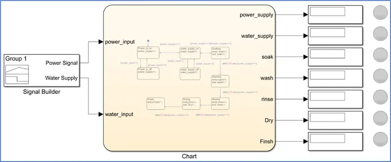
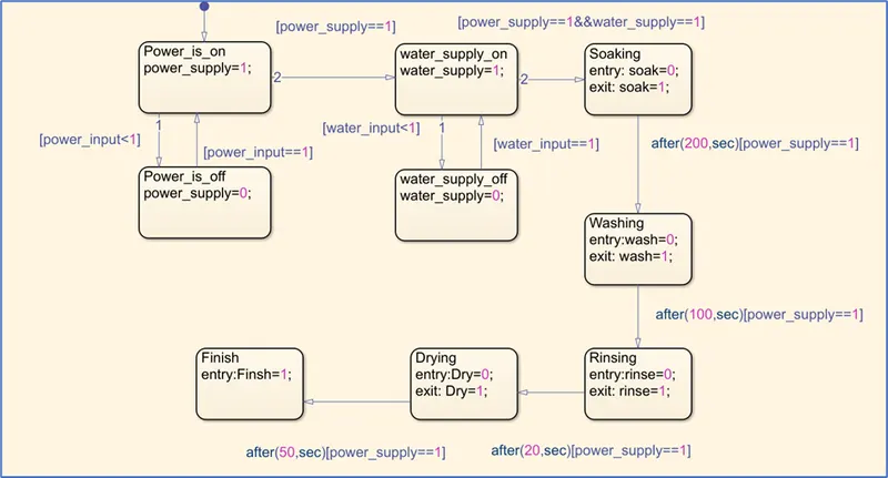
Logic used: Assuming an automatic washing machine. When the power is on and water supply is on then the next steps of the process must be initiated. If the power or water supply is off it must be indicated through a light.
Delay is given for each steps as per the requirement.
Blocks used in this model:
Signal builder: Create and generate interchangeable groups of signals whose waveforms are piecewise linear
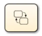
Chart: Implement control logic with finite state machine.
Display: The Display block connects to a signal in your model and displays its value during simulation.
Lamp: The Lamp block displays a color that indicates the value of the connected signal.
More details about these blocks, refer to reference section at the end of the report.
Explanation:
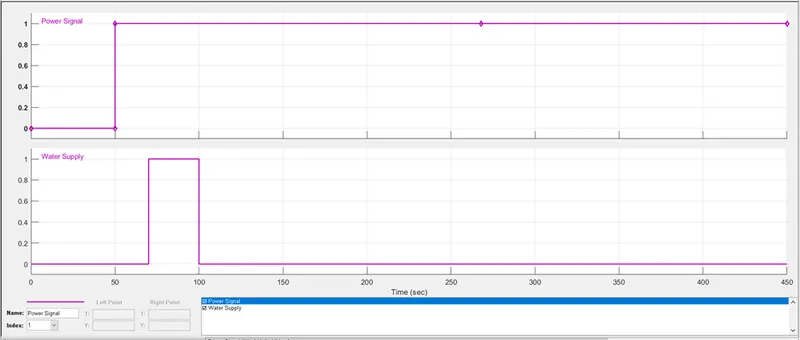
A signal builder is considered to provide “power and water” input. The power is off for about 50 seconds and switched on for rest of the time. The water supply is off for 70 seconds and switched on for another 30 seconds. The 20 seconds difference between these input supplies was provided to observe the working of water connection light.
- Inside the chart, the control logic is written.
- Conditions are written for each state and once they are satisfied, it follows the next steps in the chart.
- If the power and water supply is ‘on’, then it proceeds to soaking. The entry state is denoted with 0 and exit state with 1.
- Similarly, other states are connected and a certain delay is provided. These states are executed one after other till the final operation(state).
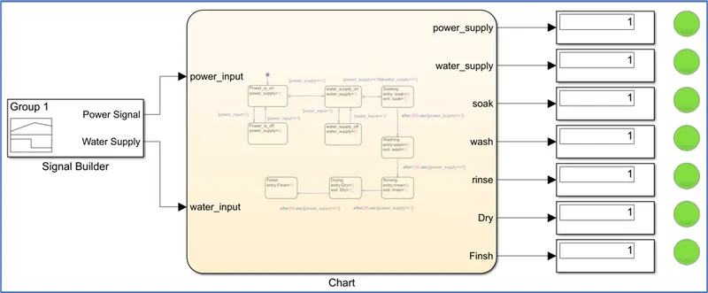
- As an output to the chart, display blocks are connected to see the operating states. Lamp blocks are connected to each output signal to know the status of the state.
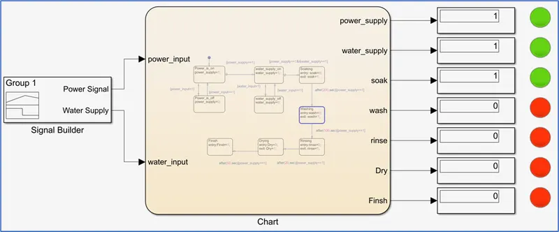
- If the state is ‘1’, then the lamp shows green, if it is ‘0’, then the lamp shows red.
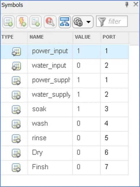
- The input and output for the chart can be defined in the symbol pane as shown below.
After the execution of all the steps, we can see that all the lamps are showing green colour.
Example: Below image shows that the soaking process is done and entered washing state.
Now, let us try to cut the power supply after soaking, and see if we get an indication. For this, we are going to slightly modify the flow and another state to it.
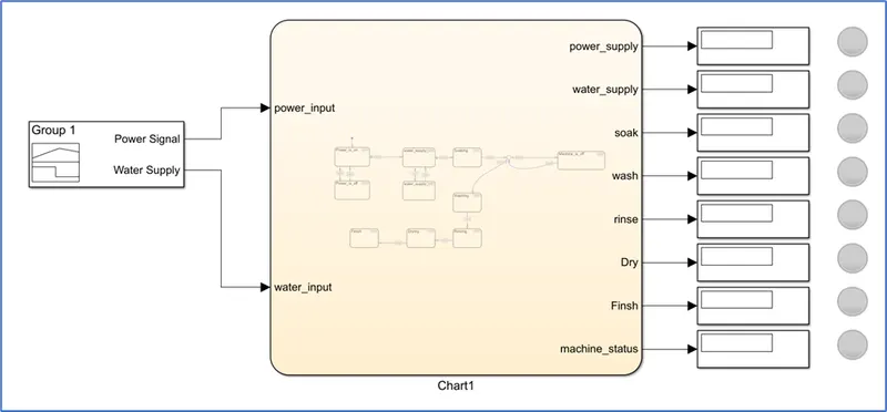
Input signal modified:
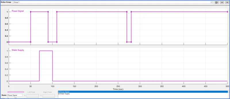
Chart is modified to a state as shown:
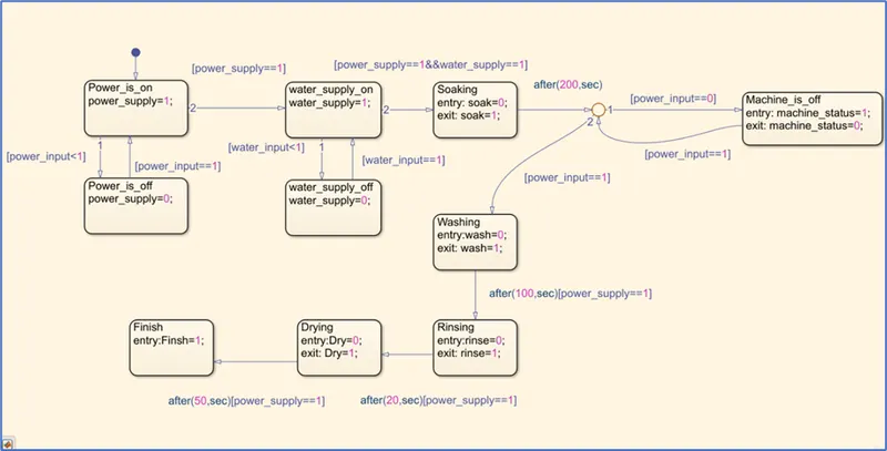
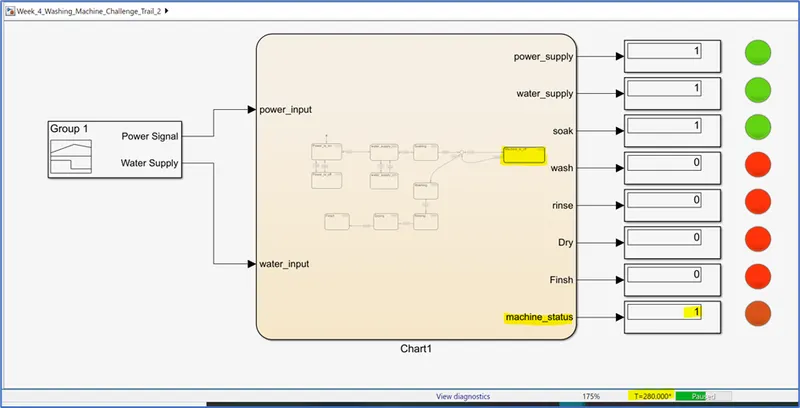
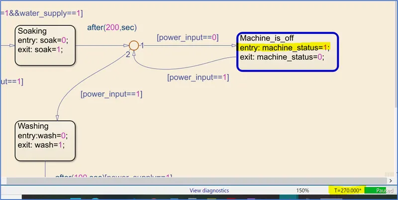
In the input, the power is set to off for 10 seconds after 270th second (see modified input signal), to observe whether the machine is going to stop or continue with further steps. From the below image we can see that the machine has stopped when there was no power signal. We can also use a ‘switch’ block as a power input and modify the model accordingly.
Question 2: Simulink model for Gear shift logic:
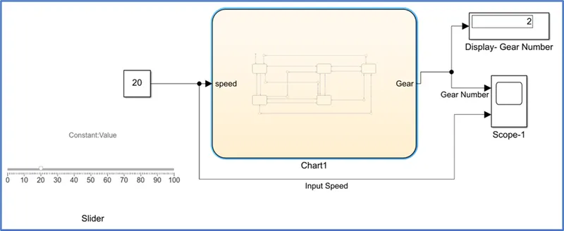
Simulink Model:
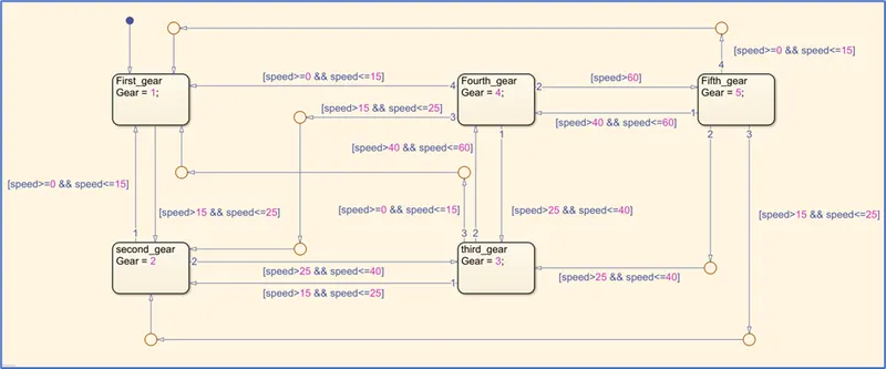
Inside the chart, the state and conditions are given as follows:
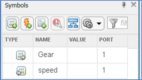
The input and output for the chart can be defined in the symbol pane as shown below.
Blocks used in this model:
Slide gain: The Slider Gain block accepts real or complex-valued scalar, vector, or matrix input. The block supports fixed-point data types.
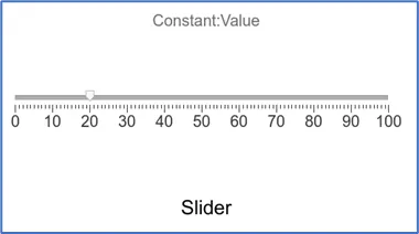
Chart: Implement control logic with finite state machine
Display: The Display block connects to a signal in your model and displays its value during simulation.
Constant: The Constant block generates a real or complex constant value signal
Scope: The Simulink Scope block display time domain signals.
More details about these blocks, refer to reference section at the end of the report.
Logic used: Assuming that a car has started and its initial speed is 0Kmph.
Starting from 1st gear, the shift can only happen from 1st --> 2nd -->3rd -->4th -->5th considering the gradual increase in speed.
Starting from 5th gear, the shift can happen as follows considering the gradual/abrupt decrease in speed:
- 5th --> 4th -->3rd -->2nd -->1st
- 5th -->4th or 5th -->3rd or 5th -->2nd or 5th -->1st
- 4th -->3rd or 4th -->2nd or 4th -->1st
- 3rd -->2nd or 3rd -->1st
Explanation:
- A slider gain block is used to vary the speed while the model is running. This block is connected to a constant.
- From the constant block, the connection is given to the chart input(speed).
- A display block and scope are attached as an output to chart to visualize the gear number and its plot with respect to the input speed.
- Inside the chart, the states (first gear, second gear…etc) are declared. The given condition (see objective) at which the gear needs to be shifted and the above-mentioned logic is used to model this.
- The stop time is set to ‘inf’ so that the input speed can be changed during the run time.
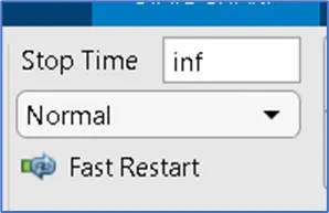
- The input speed is varied by using slider gain block and thus after some time, we can stop the simulation and check the plot.
Plot:
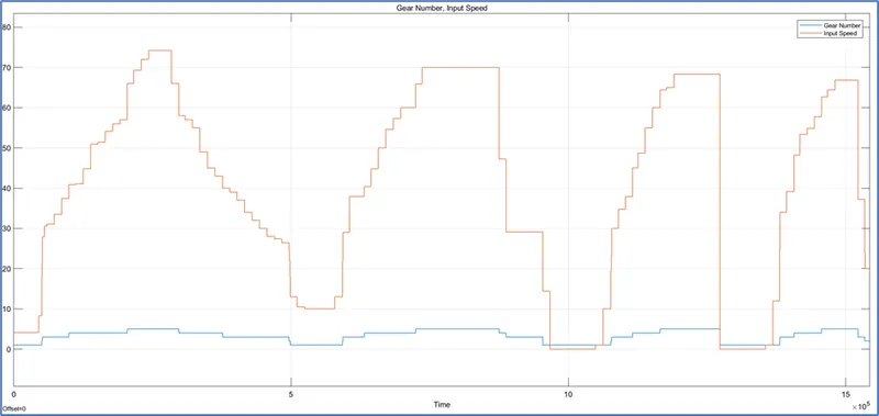
Observation: We can see that as we vary the speed the corresponding gear is selected.
Conclusion: The washing machine and gear shift logic is thus implemented by using Simulink model. These models can be improvised/customized to our requirement.
Model files are available in below path:
https://drive.google.com/drive/folders/11cf-7_l5GXGITTIYVtuB1tfJyonrSFYN?usp=sharing
References:
https://in.mathworks.com/help/stateflow/ref/chart.html?s_tid=doc_ta
https://in.mathworks.com/help/simulink/slref/signalbuilder.html?s_tid=doc_ta
https://in.mathworks.com/help/simulink/slref/dashboarddisplay.html?s_tid=doc_ta
https://in.mathworks.com/help/simulink/slref/lamp.html?s_tid=doc_ta
https://www.mathworks.com/help/releases/R2021b/simulink/slref/slidergain.html?s_tid=doc_srchtitle
https://in.mathworks.com/help/simulink/slref/scope.html?s_tid=doc_ta